element14 Community
element14 Community
    Register Log In
  • Site
  • Search
  • Log In Register
  • About Us
  • Community Hub
    Community Hub
    • What's New on element14
    • Feedback and Support
    • Benefits of Membership
    • Personal Blogs
    • Members Area
    • Achievement Levels
  • Learn
    Learn
    • Ask an Expert
    • eBooks
    • element14 presents
    • Learning Center
    • Tech Spotlight
    • STEM Academy
    • Webinars, Training and Events
    • Learning Groups
  • Technologies
    Technologies
    • 3D Printing
    • FPGA
    • Industrial Automation
    • Internet of Things
    • Power & Energy
    • Sensors
    • Technology Groups
  • Challenges & Projects
    Challenges & Projects
    • Design Challenges
    • element14 presents Projects
    • Project14
    • Arduino Projects
    • Raspberry Pi Projects
    • Project Groups
  • Products
    Products
    • Arduino
    • Avnet Boards Community
    • Dev Tools
    • Manufacturers
    • Multicomp Pro
    • Product Groups
    • Raspberry Pi
    • RoadTests & Reviews
  • Store
    Store
    • Visit Your Store
    • Choose another store...
      • Europe
      •  Austria (German)
      •  Belgium (Dutch, French)
      •  Bulgaria (Bulgarian)
      •  Czech Republic (Czech)
      •  Denmark (Danish)
      •  Estonia (Estonian)
      •  Finland (Finnish)
      •  France (French)
      •  Germany (German)
      •  Hungary (Hungarian)
      •  Ireland
      •  Israel
      •  Italy (Italian)
      •  Latvia (Latvian)
      •  
      •  Lithuania (Lithuanian)
      •  Netherlands (Dutch)
      •  Norway (Norwegian)
      •  Poland (Polish)
      •  Portugal (Portuguese)
      •  Romania (Romanian)
      •  Russia (Russian)
      •  Slovakia (Slovak)
      •  Slovenia (Slovenian)
      •  Spain (Spanish)
      •  Sweden (Swedish)
      •  Switzerland(German, French)
      •  Turkey (Turkish)
      •  United Kingdom
      • Asia Pacific
      •  Australia
      •  China
      •  Hong Kong
      •  India
      •  Korea (Korean)
      •  Malaysia
      •  New Zealand
      •  Philippines
      •  Singapore
      •  Taiwan
      •  Thailand (Thai)
      • Americas
      •  Brazil (Portuguese)
      •  Canada
      •  Mexico (Spanish)
      •  United States
      Can't find the country/region you're looking for? Visit our export site or find a local distributor.
  • Translate
  • Profile
  • Settings
Dev Tools
  • Products
  • More
Dev Tools
Forum Doubt with I2C connector
  • Forum
  • Documents
  • Files
  • Members
  • Mentions
  • Sub-Groups
  • Tags
  • More
  • Cancel
  • New
Join Dev Tools to participate - click to join for free!
Actions
  • Share
  • More
  • Cancel
Forum Thread Details
  • State Verified Answer
  • Replies 4 replies
  • Answers 2 answers
  • Subscribers 78 subscribers
  • Views 925 views
  • Users 0 members are here
  • board
  • but passthrough
  • i2c
  • layout
  • schematics
  • duplicate connector
  • prototype
  • Design
  • raspberry pi
  • psoc 4200
  • cypress psoc 4200
Related

Doubt with I2C connector

balearicdynamics
balearicdynamics over 8 years ago

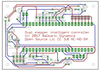
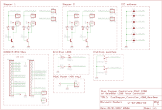
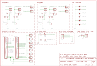
Some days ago I have assembled a first prototye of a PSoC 4200 series based on the CY8CKIT-049042xx board "implanted" over a custom board. The microcontroller can manage a couple of Stepper motors via a L298 controller board. Every unit will be controlled by a Raspberry PI via I2C protocol. Below the schematics and the first PCB.

imageimageimage

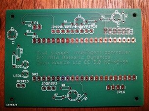
I tested the boards and worked well but I discovered a missing wire, the common ground signal between the PI and the controlled boards. The boards does not need a VCC as are powered by a different source. For prototype testing this is not a very serious problems, I wired an extra-cable to connect the two ground.

Then I have updated the schematics to a version 2 with a new PCB layout. For completeness I have added the following things:

  1. The GND pin for the I2C connector
  2. The VCC pin (not used in this particular project but useful in some other case(
  3. Replicated the connector to have the option to create an I2C bus chain from a Raspberry PI to multiple boards (with different I2C address

Below the new schematics and the new layout

imageimage

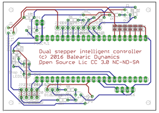
The two I2 connectors on the board can be shown in the layout in the bottom left corner.

My doubt is if it is sufficient to replicate the layout as shown in the images above or some extra circuitry is needed (e.g. to differentiate the I2C in and the out connectors). Any suggestion is welcome.


Thanks in advance.

Enrico

  • Sign in to reply
  • Cancel

Top Replies

  • shabaz
    shabaz over 8 years ago +3 verified
    Hi Enrico, To me it looks good, no need for anything extra, and no need to do anything different for the I2C in/out. I think (I'm not knowledgeable on PSoC so I'm guessing) that the PSoC has the ability…
  • balearicdynamics
    balearicdynamics over 8 years ago in reply to shabaz +2 suggested
    Hi Shabaz! Thank you for the good suggestion. With your detailed answer you got me anothrer further suggestion just based on the PSoC I2C atchitecture. The I2C component (that is one of the configurable…
  • balearicdynamics
    balearicdynamics over 8 years ago +1
    Accordingly with the suggestions of shabaz below the new schematics and layout. About the power line instead it was my mistake: PSoC support both power 3.3V and 5V so the jumper is not needed. Enrico
  • shabaz
    0 shabaz over 8 years ago

    Hi Enrico,


    To me it looks good, no need for anything extra, and no need to do anything different for the I2C in/out.

    I think (I'm not knowledgeable on PSoC so I'm guessing) that the PSoC has the ability to not configure pull-ups, because you want the Pi's pull-ups to 3.3V to be used, not any pull-up on the PSoC board to 5V.

    As an optional thing, (if you decide to use this board with say Arduino too, instead of Pi) you might want to have pull-ups on your board too, that go to a point that can either be wired to 5V (if this is the voltage the PSoC uses) or to be wired off-board to 3.3V if some other 3.3V SBC is being used that doesn't already have pull-up resistors on the I2C bus.

    You could leave the pull-up resistors unpopulated basically, but have space for them to be soldered in for any SBC that needs it. Resistors are not necessary in this scenario though.

    • Cancel
    • Vote Up +3 Vote Down
    • Sign in to reply
    • Verify Answer
    • Reject Answer
    • Cancel
  • balearicdynamics
    0 balearicdynamics over 8 years ago in reply to shabaz

    Hi Shabaz! Thank you for the good suggestion. With your detailed answer you got me anothrer further suggestion just based on the PSoC I2C atchitecture.

    The I2C component (that is one of the configurable variants of the same component in the design supporting the UART, SPI or I2C) can be set as master, multimaster of slave. As far as I know as the master represent the "bus starting" in the chainI have done a series of considerations:

    • As far as I know to make the board the most general purpose possible I will include also two optional resistors on the board in the case that the board will be used as master. When it is used as slave the resistors are not needed and should not be present.
    • The I2C power line is not needed in this specific case as it is the PSoC itself the slave. Literature says that the pull-up resistors are present on the master circuitry and in the case of different power lines values (this is the case, PSoC is powered by 5Vcc while the PI I2C design suggest to use the 3.3 V) the best practice is to pull-up the resistors on the bus with only the device with the lower VCC value. In the case instead when the PSoC for some reason is connected to other sensors it is a good idea to have a power line available anyway on the connector side. To make things complete I will add a jumper to select 5Vcc or 3.3 Vcc from the PSoC to send the power to the I2C connector side.
    • Good suggestion about the Arduino (or similar or anyway other I2C micro boards / SBC supporting this protocol). In the case of Arduino the 5Vcc of it will be sufficient to power the PSoC (acting as slave) so the I2C 4 wires connector is able to power it as well.

    What do you think of this further upgrade?

    • Cancel
    • Vote Up +2 Vote Down
    • Sign in to reply
    • Verify Answer
    • Reject Answer
    • Cancel
  • balearicdynamics
    0 balearicdynamics over 8 years ago

    Accordingly with the suggestions of shabaz below the new schematics and layout. About the power line instead it was my mistake: PSoC support both power 3.3V and 5V so the jumper is not needed.


    Enrico

    imageimage

    • Cancel
    • Vote Up +1 Vote Down
    • Sign in to reply
    • Verify Answer
    • Cancel
  • shabaz
    0 shabaz over 8 years ago in reply to balearicdynamics

    Hi Enrico,


    This looks good to me! The circuit with the resistors in case you wish to change the code and use it as I2C master is a good idea.

    • Cancel
    • Vote Up +1 Vote Down
    • Sign in to reply
    • Verify Answer
    • Reject Answer
    • Cancel
element14 Community

element14 is the first online community specifically for engineers. Connect with your peers and get expert answers to your questions.

  • Members
  • Learn
  • Technologies
  • Challenges & Projects
  • Products
  • Store
  • About Us
  • Feedback & Support
  • FAQs
  • Terms of Use
  • Privacy Policy
  • Legal and Copyright Notices
  • Sitemap
  • Cookies

An Avnet Company © 2025 Premier Farnell Limited. All Rights Reserved.

Premier Farnell Ltd, registered in England and Wales (no 00876412), registered office: Farnell House, Forge Lane, Leeds LS12 2NE.

ICP 备案号 10220084.

Follow element14

  • X
  • Facebook
  • linkedin
  • YouTube