


Earlier i had created tutorial using SDK without using Processor Expert, now in this tutorial lets create RGB toggling using SDK + Processor Expert.
You can refer to my earlier blog for most of my project settings:
Below are the basic requirements required for this project.
Required Hardware and Software:
- FRDM-K64F Board configured with JLink Debugger
(The firmware can be downloaded here: Firmware download)
- Micro USB Cable
- Kinetis Design Studio (v1.1.1 or newer)
(You can now download the GA release, KDS 1.1.1, at: KDS-WINDOWS_IDE )
- Kinetis Software Development Kit (KSDK-v1.0.1)
(Download Link Freescale Kinetis SDK_1.0.0 - Windows installer )
- Eclipse Update for Freescale Kinetis SDK 1.0.0-GA
(http://cache.freescale.com/lgfiles/sdk/SDK_1.0.0-GA_Update_for_Eclipse_1.0.1.zip)
- Reference of FRDM-K64 user guide for schematic
This has been split into different sections as below:
1. Loading the OpenSDA V2 firmware to K64F board provided from Segger:
(Refer to the link: HERE )
2. Setting up Kinetis Design Studio Environment Variable
3. Eclipse Update for Freescale Kinetis SDK 1.0.0-GA
(Refer to the link: HERE )
4. Build the platform driver library
5. Creating New Project:
Build the platform driver library
Before building and debugging any demo application in KSDK, the driver library project should be built to generate the library archives: ksdk_platform_lib.a. Because this library contains all binary codes for HAL and the peripheral drivers specific to the chip, each SoC has its own platform.a library archives.
We need to Importing platform library from the KSDK installation path and build the library, follow below steps to import and build the platform library.
Open the KDS IDE by giving your default workspace and select ‘import’ option as shown below:
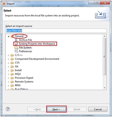
Select File>Import

Next select the option “Existing projects into Workspace” from General Tab and click “Next”
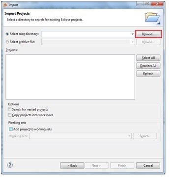
Click on “Browse” button as shown below:
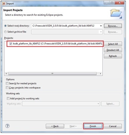
Browse to navigate to KSDK_1.0.0 installation folder and select the K64F12 folder and select ‘ok’.

Make sure the project is selected and click Finish as shown below
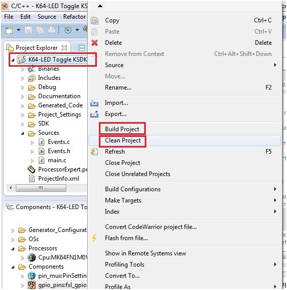
Now select the Project, right click, clean and build the project as shown below:


You can see the build progress / status in console window, if everything goes well you can see build finishes as shown:

When the build is complete, the ‘ksdk_platform_lib.a’ is generated in the directory according to the build target which is located here “C:/Freescale/KSDK_1.0.0/lib/ksdk_platform_lib/kds/K64F12/debug/ksdk_platform_lib.a”
We need to provide this path in our new project in "Cross ARM C++ Linker" option to add the KSDK library in the compiler. (this will be shown later while creating new project)
Creating New Project:
So let’s start in creating a new project using KDS + KSDK + PE IDE i.e PEx Device Initialization + SDK Drivers implementing on FRDM-K64F board.
Open KDS IDE by double clicking the KDS icon present in your desktop: It will ask for the Workspace, give the path of your choice and click ‘ok’

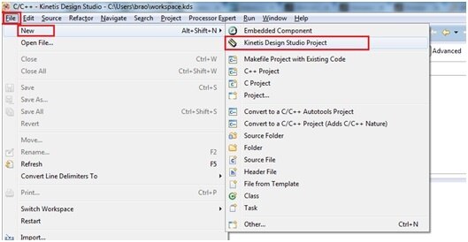
Next create a New project by clicking
File -> New -> Kinetis Design Studio Project
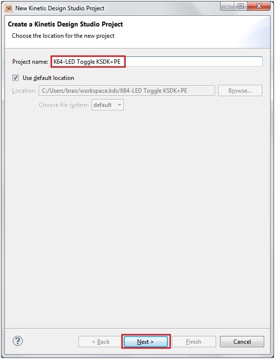
Choose project name of your choice, i have given it as “K64-LED Toggle KSDK+PE” and click Next.
You can select device either by ‘Boards’ or ‘Processor’ option as shown, here I will select the option as select by Boards as my board configuration (like gpio port pins, I2C, ports, UART pins..Etc) will be set by the tool itself so that I need not have to configure again.
If I select by ‘Processor’ then I need to configure separately myself for the GPIO’s and other required peripherals in component inspector-CPU window of the processor selected.

I am selecting the target device by Boards option and selected “FRDM-K64F” and click Next as shown below:
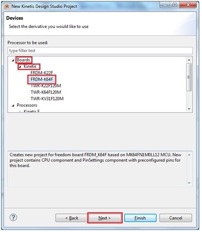
You can see the Device in target board is “MK64FN1M0LL12”
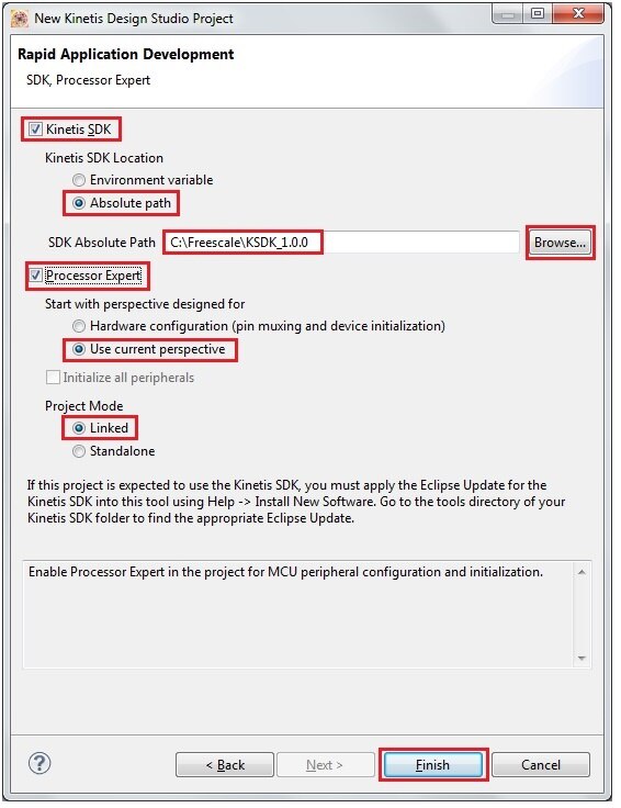
In the next screen you can find below options to be selected in Rapid Application Development window. Select the check box “Kinetis SDK”
And select the radio button “Absolute path” and browse for the SDK installation folder. In my case it is C:\Freescale\KSDK_1.0.0
Make sure that "Processor Expert" is checked as our project uses the PE initialization required for our project.
Select the option “Use current perspective” and Select “Linked”
Next click Finish button and proceed further.
You can see a KDS project window created for our New project. To see a relevant perspective windows click on ‘Windows>Reset Perspective’ as shown below:

Then click on “Processor Expert > Show Views” to see all the relevant windows
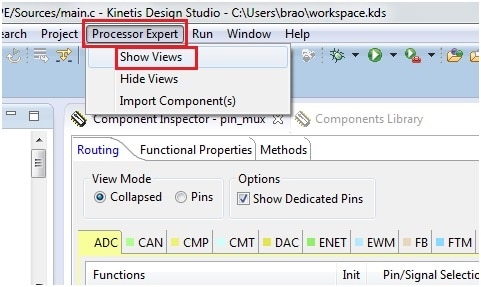
You can see below updated project window and is created and ready to include the source code. You can see there is a ‘Components’ in our project selection and ‘Component Inspector’ window as shown.

Now we need to configure the clock settings for this project:
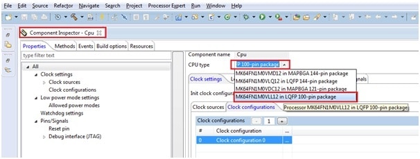
Select the CPU in Component view window

Double click on Component inspector window and select the CPU package: we select ‘MK64FN1M0VLL12’ as CPU.
Then select below option in init clock configuration:

Then below selection for clock configuration-0. In internal reference clock menu make sure you have selected tick on ‘MCGIRCLK clock’

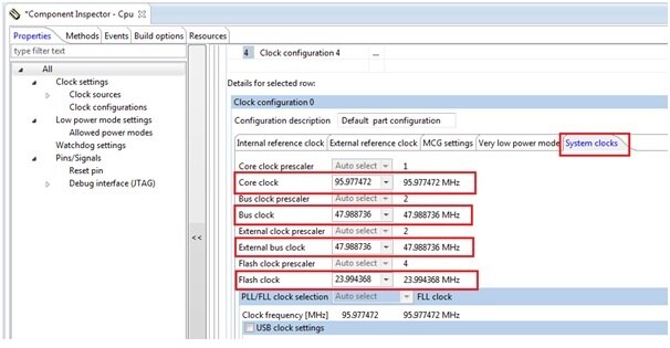
Next select MCG settings as shown below: select the option ‘IRC 48MHz’ and FLL output as 95.977472 MHz from pop down list.

Then in system clocks menu select the option as shown below for core clock, Bus clock, External bus clock, and Flash clock frequencies.
Next select on pin_mux settings as shown

As we had selected “Board” option while project creation, this comes along with configuration setting for I/O’s applicable for K64 board.
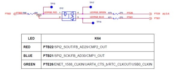
We can see PTB21 is connected to Blue LED, PTB22 is connected to Red LED, and PTE26 is connected to Green LED
The direction of the pin is ‘Not Specified’ as it is Automatic enabled - there is no user requirement for configuration. The value was selected automatically based on register configuration specified by other properties or based on after reset value.

Click on Save icon as shown below:

Now it’s time for setting up the components.
Before that refer to below hardware schematic to know the port pins to LED connection details:
Select the gpio_pins:fsl_gpio as shown below:

Now select ‘output pins’ from properties menu as shown:

Now select the configuration for “output pin number 0” as shown below which is connected to PTE26 port pin
Pin: “PTE26/ENET_1588_CLKIN/UART4_CTS_b/RTC_CLKOUT/USB_CLKIN”
Pin Name: kGpioLED1

Similarly for the other two output pins as shown below:

Pin: “PTB22/SPI2_SOUT/FB_AD29/CMP2_OUT”
Pin Name: kGpioLED2
And for output pin 2 as shown below:
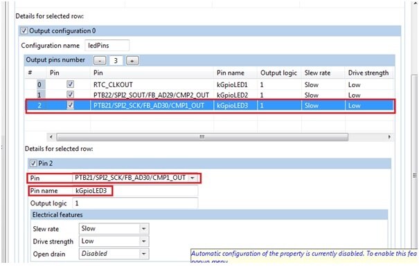
Pin: “PTB21/SPI2_SCK/FB_AD30/CMP1_OUT”
Pin Name: kGpioLED3
Now generate the code with Processor Expert as shown below:

It will synchronise the modules and generate code
To ensure the project settings are correct, clean and compile once as shown below:

And output as shown below:

A quick check of some of the generated code. When you expand the generated code section in the Project, you will see listings of header and c files.

Few of the required headers are board.h, cpu.c, cpu.h, gpio_pins.c, gpio_pins.h, hardware_init.c, pin_mux.c, pin_mux.h
Now, let’s toggle an RGB LED Using the generated libraries.
Locate “fsl_gpio_driver.h” from the folder tree. Double-click on the file.

Use the “Outline” view to navigate to the “GPIO_DRV_ClearPinOutput” function. Double-click on the function name.
KDS will navigate to the “GPIO_DRV_ClearPinOutput” function.

Copy this function and paste this in main.c
Now we need to locate the name of the GPIO assigned to the RGB LED
Select “gpio_pins.h” from Generated code folder as shown.
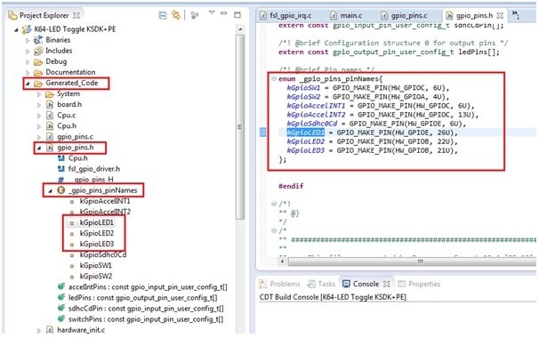
You can see all the i/o pins have been defined in gpio_pins.h folder which we had assigned in component inspector earlier.
kGpioLED1 > Green Led
kGpioLED2 > Red Led
kGpioLED3 > Blue Led

Adding these gpio names as argument to the function GPIO_DRV_ClearPinOutput(), and GPIO_DRV_SetPinOutput() selected earlier i.e
GPIO_DRV_ClearPinOutput(kGpioLED1); //Green led on GPIO_DRV_SetPinOutput(kGpioLED1); // Green led off
Using this information we will write our software code as shown below
for(;;){
GPIO_DRV_ClearPinOutput(kGpioLED1); //Green led on
for(i=0;i<=10000000;i++);
GPIO_DRV_SetPinOutput(kGpioLED1); // Green led off
for(i=0;i<=10000000;i++);
GPIO_DRV_ClearPinOutput(kGpioLED2); //Red led on
for(i=0;i<=10000000;i++);
GPIO_DRV_SetPinOutput(kGpioLED2); // Red led off
for(i=0;i<=10000000;i++);
GPIO_DRV_ClearPinOutput(kGpioLED3); //Blue led on
for(i=0;i<=10000000;i++);
GPIO_DRV_SetPinOutput(kGpioLED3); // Blue led off
for(i=0;i<=10000000;i++);
}
Here is my main.c file contents
/* ###################################################################
** Filename : main.c
** Project : K64-LED Toggle KSDK+PE
** Processor : MK64FN1M0VLL12
** Version : Driver 01.01
** Compiler : GNU C Compiler
** Date/Time : 2014-09-15, 12:26, # CodeGen: 0
** Abstract :
** Main module.
** This module contains user's application code.
** Settings :
** Contents :
** No public methods
**
** ###################################################################*/
/*!
** @file main.c
** @version 01.01
** @brief
** Main module.
** This module contains user's application code.
*/
/*!
** @addtogroup main_module main module documentation
** @{
*/
/* MODULE main */
/* Including needed modules to compile this module/procedure */
#include "Cpu.h"
#include "Events.h"
#include "pin_mux.h"
#include "gpio_pins.h"
#if CPU_INIT_CONFIG
#include "Init_Config.h"
#endif
/* User includes (#include below this line is not maintained by Processor Expert) */
/*lint -save -e970 Disable MISRA rule (6.3) checking. */
int main(void)
/*lint -restore Enable MISRA rule (6.3) checking. */
{
/* Write your local variable definition here */
/*** Processor Expert internal initialization. DON'T REMOVE THIS CODE!!! ***/
PE_low_level_init();
/*** End of Processor Expert internal initialization. ***/
/* Write your code here */
int i;
for(;;){
GPIO_DRV_ClearPinOutput(kGpioLED1); //Green led on
for(i=0;i<=10000000;i++);
GPIO_DRV_SetPinOutput(kGpioLED1); // Green led off
for(i=0;i<=10000000;i++);
GPIO_DRV_ClearPinOutput(kGpioLED2); //Red led on
for(i=0;i<=10000000;i++);
GPIO_DRV_SetPinOutput(kGpioLED2); // Red led off
for(i=0;i<=10000000;i++);
GPIO_DRV_ClearPinOutput(kGpioLED3); //Blue led on
for(i=0;i<=10000000;i++);
GPIO_DRV_SetPinOutput(kGpioLED3); // Blue led off
for(i=0;i<=10000000;i++);
}
/* For example: for(;;) { } */
/*** Don't write any code pass this line, or it will be deleted during code generation. ***/
/*** RTOS startup code. Macro PEX_RTOS_START is defined by the RTOS component. DON'T MODIFY THIS CODE!!! ***/
#ifdef PEX_RTOS_START
PEX_RTOS_START(); /* Startup of the selected RTOS. Macro is defined by the RTOS component. */
#endif
/*** End of RTOS startup code. ***/
/*** Processor Expert end of main routine. DON'T MODIFY THIS CODE!!! ***/
for(;;){}
/*** Processor Expert end of main routine. DON'T WRITE CODE BELOW!!! ***/
} /*** End of main routine. DO NOT MODIFY THIS TEXT!!! ***/
/* END main */
/*!
** @}
*/
/*
** ###################################################################
**
** This file was created by Processor Expert 10.4 [05.10]
** for the Freescale Kinetis series of microcontrollers.
**
** ###################################################################
*/
Explanation of code
You can see these LED’s are connected in active-Low connection, i.e common Anode, we should provide Low signal to port pins to glow a LED.
Below is line of code where Green led is switched on for some delay and switched off for some time.
GPIO_DRV_ClearPinOutput(kGpioLED1); //Green led on
for(i=0;i<=10000000;i++); //Delay
GPIO_DRV_SetPinOutput(kGpioLED1); // Green led off
for(i=0;i<=10000000;i++); //Delay
Below is line of code where Red led is switched on for some delay and switched off for some time.
GPIO_DRV_ClearPinOutput(kGpioLED2); //Red led on
for(i=0;i<=10000000;i++);
GPIO_DRV_SetPinOutput(kGpioLED2); // Red led off
for(i=0;i<=10000000;i++);
Below is line of code where Red led is switched on for some delay and switched off for some time.
GPIO_DRV_ClearPinOutput(kGpioLED3); //Blue led on
for(i=0;i<=10000000;i++);
GPIO_DRV_SetPinOutput(kGpioLED3); // Blue led off
for(i=0;i<=10000000;i++);
Now it’s time to clean and compile/Build the project

You can see the build output as shown below:

Now we need to setup for Debug configuration:
As a pre-requisite the board is loaded with “JLink_OpenSDA_V2.bin” OpenSDA_V2 application driver file. And same will be used for connecting hardware to PC.
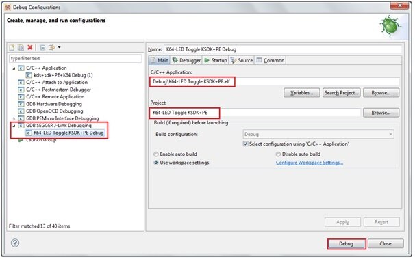
Select ‘GDB SEGGER J-Link Debugging and double click or right click and select ‘New’

You can see a default name as project name as shown below: make sure under ‘Main’ tab C/C++ application there is *.elf file name of your project.
Next click on Debugger tab check ‘Device name’ field by default it will be blank.
Now specify device name “MK64FN1M0xxx12” and click on apply and close the Debug configuration window as shown below:

Now connect FRDM-K64F board to PC through USB mini connector connecting to “SDA USB” port of board.
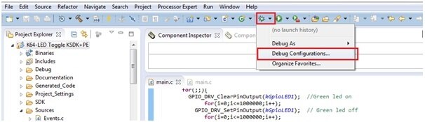
Click on Debug icon as shown and select Debug Configuration and proceed to debug your project:

Click on Debug

Now you can see the Debug window opens which is ready for single stepping or Running the project as shown:

Click on Resume button or press ‘F8’ button for executing the project.
You can see the output of LED toggling.
Below is the video recording of the project execution.
And i have enclosed the project folder for quick view and execution.
Happy Toggling using KDS+SDK+PE 
 |


