|
I'm writing a flow to automate long-term temperature measurement.
|
Adapted hardware
For accurate thermocouple measurements, you need to know the temperature at its cold junction - the wiring point where the thermocouple cables are connected to the meter. A sensor needs to be placed as close as possible to that point. In my case: I put a Pt100 RTD inside the terminals of a Keithley 2000-SCAN card. The measurement device has to be connected to channel 1 to make the compensation work with the DMM6500 built-in settings.
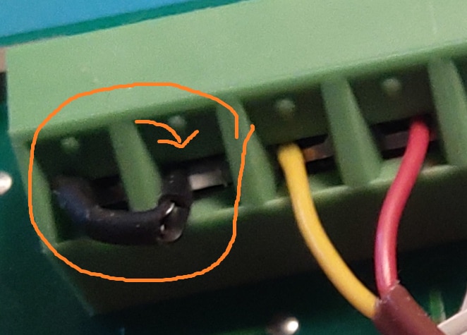
photo: the Pt100 installed inside the 2000-SCAN channel 1. A K-type thermocouple is connected to channel 2.
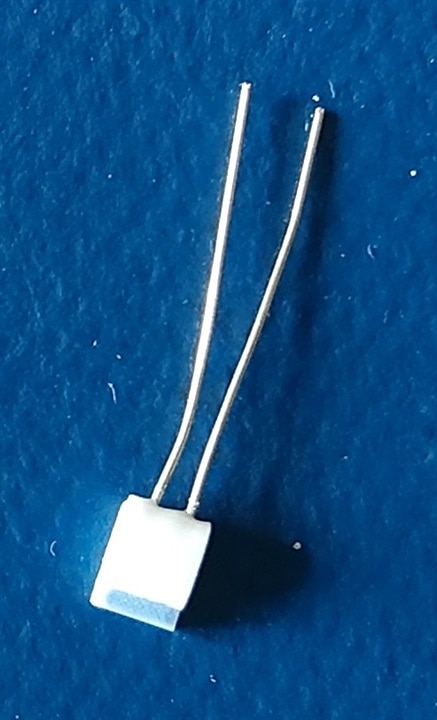
The Pt100 RTD
Test with the DMM6500 front panel
After measuring that the resistance on channel 1 was around 100Ω - the value of a Pt100, I tested the setup using the front pannel options of the meter.
I set channel 1 as a Pt100 channel:
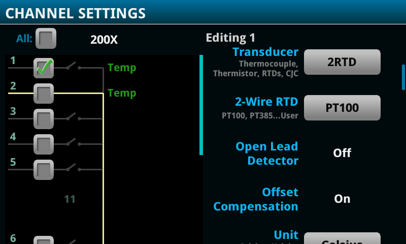
Then I set up channel 2 as a K-type thermocouple, with external compensation. The DMM6500 will always use channel 1 as the cold junction temperature reference.
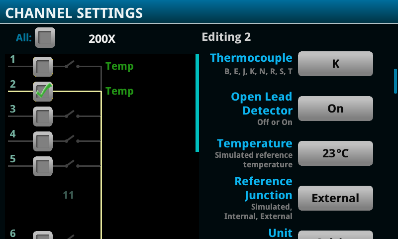
Then I ran the scan and showed the values in a grid:
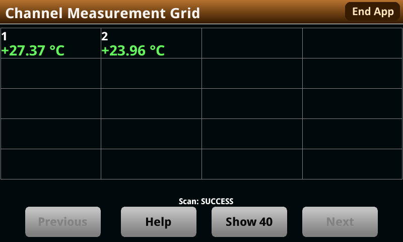
Channel 2 is the temperature of the DOT (my lab, with a light shining on the thermocouple area). Channel 1 shows the temperature at the terminals inside the meter, as reported by the Pt100 RTD. The RTD is sampled every cycle. If the temperature inside the meter drifts, it impacts the thermocouple's measurements. But the compensation algorithm takes care that this is corrected.
Adapted DMM6500 Driver example
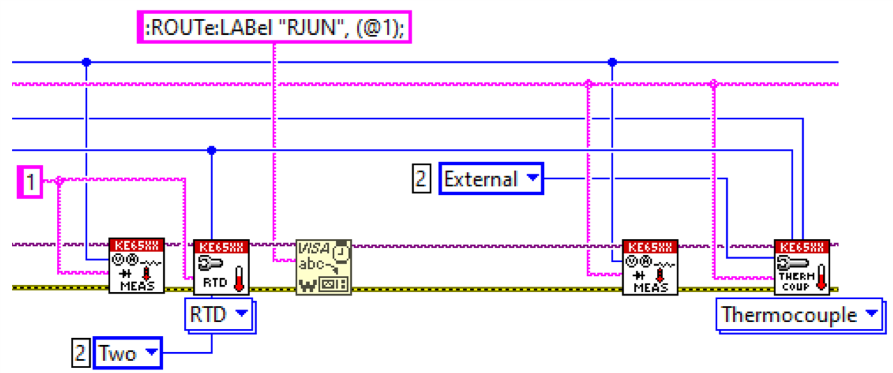
The Keithley LabVIEW driver has examples for two scenarios: simulated cold junction compensation, or the internal compensation available on their excellent 2001-TSCAN card. I added the external option, so that I could use my Pt100 sensor:
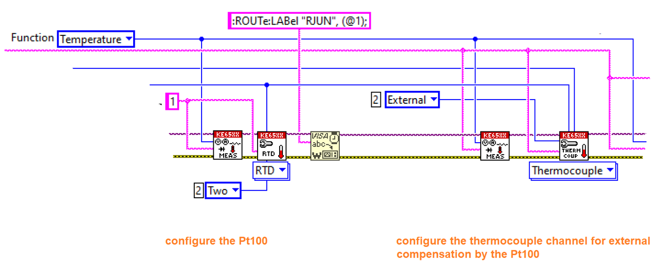
image: the cold junction reference and the thermocouple channels configuration. I also gave it a name (RJUN).
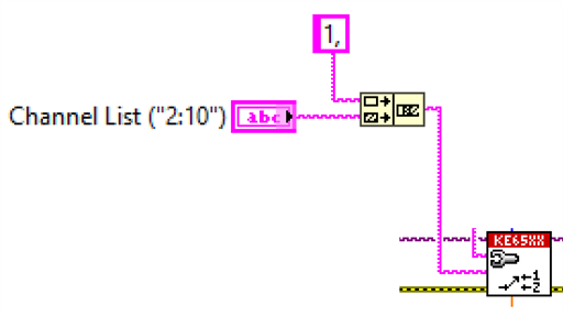
image: Before sampling, I take care that the cold junction reference channel is added in front of the selected thermocouple channel list. It needs to be sampled before the thermocouples to get the best results
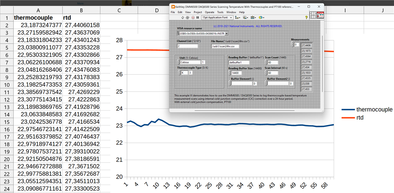
The driver example's front panel is adapted to remove the simulation field. All the rest was kept the same. Here is a single sample taken with the Pt100 compensation. Result 2 is again the thermocouple's compensated measurement. Result 1 shows the value reported by the Pt100.
The LabVIEW flow (community edition licensed): labview_projects.zip


