Introduction:
I have been trying to setup the pi pico with Labview for the past few days. Earlier, I was facing many problems and was totally confused after going through multiple online guides but slowly things started to fall into the picture and soon I realized it was actually pretty easy. So, I decided to write a blog on the process. Here I will be going through the steps to setup pico with Labview on Windows.
Installing the Software:
Installing Pi Pico SDK:
The detailed guide is here: getting-started-with-pico section 9.2
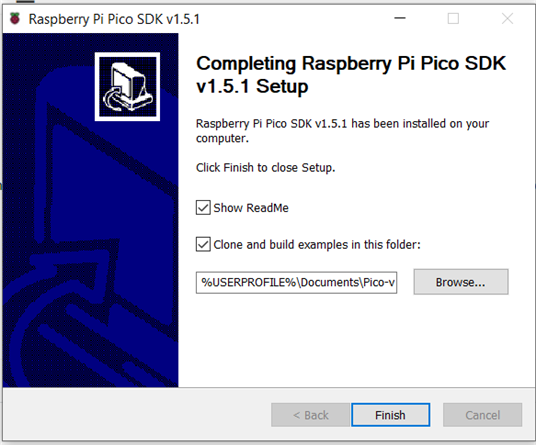
First of all we will need the Pi pico-sdk which can be found at pico-setup-windows git repo. Go the latest release and download the .exe file. Run this executable. This will install the following softwares:
- Arm GNU Toolchain
- CMake
- Ninja
- Python 3.9
- Git
- VSCode
- OpenOCD
After the installation completes, tick the "Clone and build examples" checkbox. This will clone some examples to run with pico.

After the installation completes successfully, we can try running some example code on the pico.
A "Pico - Visual Studio Code" shortcut will be created in the start menu. Open it.

Open the pico-examples folder that we cloned.
In the VSCode window, at the bottom, change the active kit to Pico ARM GCC.

We will build the "blink" project. Click on the "CMake" button on the sidebar and go to the blink.elf file then click on build.

If the build is successful, it will print the below message:
In the build directory, a .uf2 file will get generated. Now, press the bootsel button on the pico and connect it to the laptop via a USB cable then release the button. Now drag and drop the .uf2 file onto the Mass Storage Device.

So, we have successfully loaded "blink" code on the pico using the pico-sdk and VSCode.
Now, we will follow similar steps to install the SCPI Labtool firmware on the Pico.
Installing SCPI Labtool on Pico:
In this section, we will create a .uf2 firmware of the SCPI Labtool and load it onto the Pico. Alternatively, the firmware can be downloaded from this link and this section can be skipped.
Go to the pico_scpi_usbtmc_labtool git repo and clone it using the below command. I was facing some issue in Windows CMD with --recurse-submodules option but after running in Git CMD, I was able to clone the submodules also.
git clone https://github.com/jancumps/pico_scpi_usbtmc_labtool.git --recurse-submodules
Now clone the SCPI Library.
Add the below variables to the environment. The paths can be different in your case.

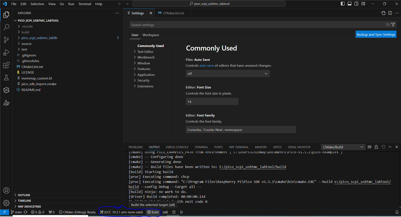
Now open Pico - VSCode and open the pico_scpi_usbtmc_labtool folder. Select the active kit and click on build.

After the build completes successfully, a pico_scpi_usbtmc_labtool.uf2 file will be generated inside the build folder.
Now plug in the pico & upload this firmware.
PICO_SCPI_LABTOOL_LABVIEW_DRIVER:
We will clone one more github repo: pico_scpi_labtool_labview_driver. This repo has the labview drivers and some example VIs which we will use later.
Accessing Pico from Labview:
Download and install the VISA Interactive Control Application from this link.
With Pico plugged in and firmware installed, open NI Max (Installed with Labview). You can give a meaningful name to your device and click on save.

Running an example VI:
Now, go to the pico_scpi_labtool_labview_driver folder. Inside scpi_driver, open Example_analog_read.vi. Now, select the name of your device in the "VISA resource name" field.

Run it. You will see that it is reading some values on the front panel.
Connecting a sensor:
According to this page. The pin number 0 corresponds to the GP26 pin of the pico. So, I connected a photo interrupt sensor to this pin and checked the values read on the front panel. The connections are as follows:
Sensor VCC - Pico 3V3
Sensor GND - Pico GND
Sensor OUT - Pico GP26
Useful Links:
- getting_started_with_pico section 9.2
- scpi_parser
- pico_scpi_usbtmc_labtool
- SCPI command and Labview Driver reference
- pico_scpi_labtool_labview_driver
EDIT - In release 7 of pico_scpi_usbtmc_labtool, there is no need to clone the scpi_parser library separately and setting the SCPI_LIB_PATH.
