element14 Community
element14 Community
    Register Log In
  • Site
  • Search
  • Log In Register
  • Members
    Members
    • Benefits of Membership
    • Achievement Levels
    • Members Area
    • Personal Blogs
    • Feedback and Support
    • What's New on element14
  • Learn
    Learn
    • Learning Center
    • eBooks
    • STEM Academy
    • Webinars, Training and Events
    • More
  • Technologies
    Technologies
    • 3D Printing
    • FPGA
    • Industrial Automation
    • Internet of Things
    • Power & Energy
    • Sensors
    • More
  • Challenges & Projects
    Challenges & Projects
    • Design Challenges
    • element14 presents
    • Project14
    • Arduino Projects
    • Raspberry Pi Projects
    • More
  • Products
    Products
    • Arduino
    • Dev Tools
    • Manufacturers
    • Raspberry Pi
    • RoadTests & Reviews
    • Avnet Boards Community
    • More
  • Store
    Store
    • Visit Your Store
    • Choose Another Store
      • Europe
      •  Austria (German)
      •  Belgium (Dutch, French)
      •  Bulgaria (Bulgarian)
      •  Czech Republic (Czech)
      •  Denmark (Danish)
      •  Estonia (Estonian)
      •  Finland (Finnish)
      •  France (French)
      •  Germany (German)
      •  Hungary (Hungarian)
      •  Ireland
      •  Israel
      •  Italy (Italian)
      •  Latvia (Latvian)
      •  
      •  Lithuania (Lithuanian)
      •  Netherlands (Dutch)
      •  Norway (Norwegian)
      •  Poland (Polish)
      •  Portugal (Portuguese)
      •  Romania (Romanian)
      •  Russia (Russian)
      •  Slovakia (Slovak)
      •  Slovenia (Slovenian)
      •  Spain (Spanish)
      •  Sweden (Swedish)
      •  Switzerland(German, French)
      •  Turkey (Turkish)
      •  United Kingdom
      • Asia Pacific
      •  Australia
      •  China
      •  Hong Kong
      •  India
      •  Korea (Korean)
      •  Malaysia
      •  New Zealand
      •  Philippines
      •  Singapore
      •  Taiwan
      •  Thailand (Thai)
      • Americas
      •  Brazil (Portuguese)
      •  Canada
      •  Mexico (Spanish)
      •  United States
      Can't find the country/region you're looking for? Visit our export site or find a local distributor.
  • Translate
  • Profile
Cypress Kits
  • Products
  • Dev Tools
  • Cypress Kits
  • More
  • Cancel
Cypress Kits
Forum PSoC 4 Pioneer Kit Community Project#041 – Thermistor Example
  • Blog
  • Forum
  • Documents
  • Members
  • Mentions
  • Sub-Groups
  • Tags
  • More
  • Cancel
  • New
Cypress Kits requires membership for participation - click to join
Actions
  • Share
  • More
  • Cancel
Forum Thread Details
  • Replies 7 replies
  • Subscribers 15 subscribers
  • Views 373 views
  • Users 0 members are here
  • 100projects
Related

PSoC 4 Pioneer Kit Community Project#041 – Thermistor Example

cy.wbz
cy.wbz over 8 years ago

Hello!


In today’s example we are creating a simple thermistor project that reports data up to the Bridge Control Panel using the PSoC 5LP device as a USB-UART bridge.


Forum Post Attachments:


At the bottom of this post we are including the following items:

  • Example Project Zip File
  • Zip File of Images
    • Project Schematic
    • Component Configurations


Components Used:


The user can download the example project at the bottom of this post. The project uses the following list of Creator Components:

  • UART
  • Thermistor
  • ADC SAR
  • AMux


The components are configured by right clicking on the component in your Top Design schematic view and selecting Configure. Please enable the following selections in the Configuration windows for the listed components above.


Firmware Description:


The main.c firmware is included in the example project. Please review the commented sections for more details.


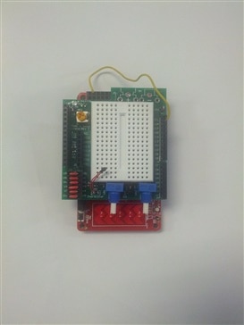
The Thermistor example was built using a custom Breadboard shield developed by Cypress, you can use the sparkfun breadboard to build this example. In this example we use a GE measurement and control sensorGE measurement and control sensor.


The project firmware pulls the value from the Thermistor using the ADC SAR and reports that value over the UART. We will then use the Bridge Control Panel to display that value in a chart format. This will allow us to plot the temperature over time.


Please refer to example #015 that uses the Bridge Control Panel and the USB-UART functionality. This example will instruct the user on how to setup the Bridge Control Panel for this example. When you’ve set up your design please use the following Bridge Control Panel commands and settings:


rx8 [h = 55] @1Temp @0Temp [t = aa]


Hardware Connections:


Connect a breadboard kit to the Pioneer Kit, the suggestion is to use the Sparkfun breadboard kit. Take the Thermistor and connect it to the Pioneer Kit using the following schematic:


Test Your Project:


Program the kit and then launch the Bridge Control Panel to read out the Thermistor values. The user can pinch the Thermistor with their fingers to drive up temperature on the Thermistor.


I hope this example can help you in your design.


Best,

Matt

Attachments:
4048.Project Images.zip
PSoC4_Thermistor.cyprj.Archive03.zip
  • Reply
  • Cancel
  • Cancel

Top Replies

  • jesusantoniocar
    jesusantoniocar over 8 years ago in reply to cy.gul +1

    Hello Matt.

    Thanks for this project.

    Gagan you have reason extremely cheap! project in cost . I am waiting for components to  build and test this project in my house.


    best regards,


    Jesus Antonio.

  • greatunclebulgaria
    greatunclebulgaria over 8 years ago +1

    Hi Matt,


    Great series of examples, looking forward to the robots!


    Could you supply the pins used on the PSoC4 board for the 3 (plus Vss) pins? This way we could use any breadboard.


    I assume the 10k reference…

  • cy.gul
    cy.gul over 8 years ago

    another nice analog project, thanks Matt.


    Thermistors are great to measure external temperature, why? -

    • they have pretty good temperature range (-100s to +100s of degrees)
    • pretty good accuracy (2-5%)
    • easy to use on breadboard
    • robust - waterproof, work at any voltage, dont easy break
    • extremely cheap!


    but to get thermistors working well, you need a couple things -

    • good ADC - PSoC provides that with an easy to use and muxable SARADC Component
    • firmware and code for voltage to temperate conversion and calibration - PSoC provides all of this in "Thermistor Calculator" Component so  you don't have to write any routine yourself


    Now you can stick you Pioneer Kit into all sorts of places to measure ambient temperature. I know friends who are using it to measure temperature their office, another one monitoring his beer brewing temperature, while a third is using it to monitor greenhouse temperature.

    • Cancel
    • Up 0 Down
    • Reply
    • Cancel
  • jesusantoniocar
    jesusantoniocar over 8 years ago in reply to cy.gul

    Hello Matt.

    Thanks for this project.

    Gagan you have reason extremely cheap! project in cost . I am waiting for components to  build and test this project in my house.


    best regards,


    Jesus Antonio.

    • Cancel
    • Up +1 Down
    • Reply
    • Cancel
  • greatunclebulgaria
    greatunclebulgaria over 8 years ago

    Hi Matt,


    Great series of examples, looking forward to the robots!


    Could you supply the pins used on the PSoC4 board for the 3 (plus Vss) pins? This way we could use any breadboard.


    I assume the 10k reference resistor is "hidden" somewhere?


    Thanks


    David

    • Cancel
    • Up +1 Down
    • Reply
    • Cancel
  • cy.wbz
    cy.wbz over 8 years ago in reply to greatunclebulgaria

    David,


    The motor examples will start next week. We've got a couple of robot examples using motors. I'll put out a post today letting everyone know what's coming down the line next week.


    The Vss pins on the headers are described on page 28 of the kit user guide. http://www.cypress.com/CY8CKit-042 You can download the guide at the bottom of the page.


    The blue lines and resistors/thermistors on the schematic design are external components. In the schematic view you have the ability to layout your entire system, both hardware internal to PSoC and hardware external to PSoC. So the 10k resistor you will need to supply in your design. You see this in example #32 to the extreme. There are only a few components, clocks, and pins in the design, but the schematic is loaded with descriptions of the external components.


    Does this answer your questions?


    Thanks!

    -Matt

    • Cancel
    • Up 0 Down
    • Reply
    • Cancel
  • greatunclebulgaria
    greatunclebulgaria over 8 years ago in reply to cy.wbz

    Morning Matt,


    Hope you had a good weekend.


    A lot of the other projects have "Hardware Connection" diagrams which show which pins are used on the Pioneer board, and connected to what externally.


    I don't know the layout of your custom breadboard shield, so I can't tell where the thermister is connected, also the photo you have does not show the 10k resistor, hence my "hidden" comment.


    I realise all the information can be gleened from the software, I was just being lazy, it was Friday (I don't get to see your projects for a day, must be the electrons slowing down crossing over the Atlantic!)


    Thanks again


    David

    • Cancel
    • Up 0 Down
    • Reply
    • Cancel
  • Former Member
    Former Member over 8 years ago

    Hello Matt!

    First of all, I wish to thank you for the example and the materials that you provided.

    I am rather new to all of this.

    Second of all, I wish to extend your example in order to measure temperature not with one, but with three thermistors.

    Do you think that would be possible?

    I must mention that I have the same board a PSoC 4 Pioneer KIT and I tried and succeeded to follow your example.

    Thank you, in advance for the help:-)!


    Alex

    • Cancel
    • Up 0 Down
    • Reply
    • Cancel
  • ymaldonado01
    ymaldonado01 over 5 years ago

    Hi Matt, i was wondering how I would set up the circuit using a standard breadboard? thanks for the help.

    • Cancel
    • Up 0 Down
    • Reply
    • Cancel
Element14

element14 is the first online community specifically for engineers. Connect with your peers and get expert answers to your questions.

  • Members
  • Learn
  • Technologies
  • Challenges & Projects
  • Products
  • Store
  • About Us
  • Feedback & Support
  • FAQs
  • Terms of Use
  • Privacy Policy
  • Legal and Copyright Notices
  • Sitemap
  • Cookies

An Avnet Company © 2022 Premier Farnell Limited. All Rights Reserved.

Premier Farnell Ltd, registered in England and Wales (no 00876412), registered office: Farnell House, Forge Lane, Leeds LS12 2NE.

ICP 备案号 10220084.

Follow element14

  • Facebook
  • Twitter
  • linkedin
  • YouTube