element14 Community
element14 Community
    Register Log In
  • Site
  • Search
  • Log In Register
  • About Us
  • Community Hub
    Community Hub
    • What's New on element14
    • Feedback and Support
    • Benefits of Membership
    • Personal Blogs
    • Members Area
    • Achievement Levels
  • Learn
    Learn
    • Ask an Expert
    • eBooks
    • element14 presents
    • Learning Center
    • Tech Spotlight
    • STEM Academy
    • Webinars, Training and Events
    • Learning Groups
  • Technologies
    Technologies
    • 3D Printing
    • FPGA
    • Industrial Automation
    • Internet of Things
    • Power & Energy
    • Sensors
    • Technology Groups
  • Challenges & Projects
    Challenges & Projects
    • Design Challenges
    • element14 presents Projects
    • Project14
    • Arduino Projects
    • Raspberry Pi Projects
    • Project Groups
  • Products
    Products
    • Arduino
    • Avnet Boards Community
    • Dev Tools
    • Manufacturers
    • Multicomp Pro
    • Product Groups
    • Raspberry Pi
    • RoadTests & Reviews
  • Store
    Store
    • Visit Your Store
    • Choose another store...
      • Europe
      •  Austria (German)
      •  Belgium (Dutch, French)
      •  Bulgaria (Bulgarian)
      •  Czech Republic (Czech)
      •  Denmark (Danish)
      •  Estonia (Estonian)
      •  Finland (Finnish)
      •  France (French)
      •  Germany (German)
      •  Hungary (Hungarian)
      •  Ireland
      •  Israel
      •  Italy (Italian)
      •  Latvia (Latvian)
      •  
      •  Lithuania (Lithuanian)
      •  Netherlands (Dutch)
      •  Norway (Norwegian)
      •  Poland (Polish)
      •  Portugal (Portuguese)
      •  Romania (Romanian)
      •  Russia (Russian)
      •  Slovakia (Slovak)
      •  Slovenia (Slovenian)
      •  Spain (Spanish)
      •  Sweden (Swedish)
      •  Switzerland(German, French)
      •  Turkey (Turkish)
      •  United Kingdom
      • Asia Pacific
      •  Australia
      •  China
      •  Hong Kong
      •  India
      •  Korea (Korean)
      •  Malaysia
      •  New Zealand
      •  Philippines
      •  Singapore
      •  Taiwan
      •  Thailand (Thai)
      • Americas
      •  Brazil (Portuguese)
      •  Canada
      •  Mexico (Spanish)
      •  United States
      Can't find the country/region you're looking for? Visit our export site or find a local distributor.
  • Translate
  • Profile
  • Settings
Cypress Kits
  • Products
  • Dev Tools
  • Cypress Kits
  • More
  • Cancel
Cypress Kits
Forum PSoC 4 Pioneer Kit Community Project#061 – Nokia 5110 LCD Interface
  • Blog
  • Forum
  • Documents
  • Polls
  • Files
  • Members
  • Mentions
  • Sub-Groups
  • Tags
  • More
  • Cancel
  • New
Join Cypress Kits to participate - click to join for free!
Actions
  • Share
  • More
  • Cancel
Forum Thread Details
  • Replies 19 replies
  • Subscribers 30 subscribers
  • Views 3960 views
  • Users 0 members are here
Related

PSoC 4 Pioneer Kit Community Project#061 – Nokia 5110 LCD Interface

cy.wbz
cy.wbz over 12 years ago

Hello!


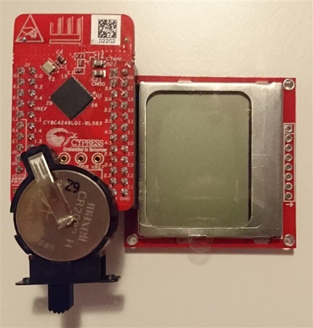
Today’s example we are showcasing how to interface to the Nokia 5110 LCD screen with the PSoC 4 Pioneer Kit. This simple display provides a 84 x 48 Graphics LCD that was used in the Nokia 5110 model in 1998. This example provides a simple example to write text and an image on the LCD screen. This example uses a bit-banging method for sending the data & clock from the CPU to the LCD panel. The project does not require any UDB resources, therefore it can be used with the PSoC 4 (42xx and 41xx families).


image


Forum Post Attachments:


At the bottom of this post we are including the following items:

  • Example Project Zip File
  • Zip File of Images
    • Project Schematic
    • Component Configurations


Components Used:


The user can download the example project at the bottom of this post. The project uses the following list of Creator Components:

  • Annotated Component for Kit-042
  • CyPins


Firmware Description:


The main.c firmware is included in the example project. Please review the commented sections for more details.


In this example we provide you with a couple of firmware based files named “Nokia5110LCD.c” and  “Nokia5110LCD.h”. These files are the source & header files required for using APIs. In this example we support the following APIs to control the Nokia 5110 LCD screen.

  • void LCD_Character(uint8)
  • void LCD_Clear(void)
  • void LCD_Init(void)
  • void LCD_String(char*)
  • void LCD_Write(uint8, uint8)
  • void Send_Data(int8)
  • void LCD_gotoXY(uint8, uint8)
  • void LCD_Bitmap(char*)


The main.c simply calls the APIs defined in the source file for initialization & for displaying the string on the LCD.


In this example, LCD initialization is done as specified in the datasheet of PCD8544 LCD driver which is used in the LCD panel. It is not necessary to use all 8 pins of PSoC 4 for interfacing this LCD. Reset, Chip Enable, Power, Backlight & Ground pins can be connected to fixed voltage levels on the board. Only Data/Command, Data & Clock pins are used for sending the data to LCD.


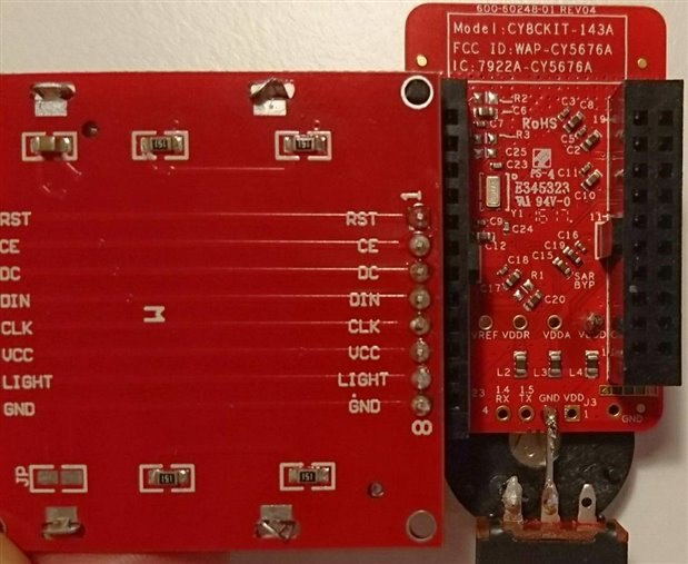
Hardware Connections:


In this example we are not using any specific headers or shields. Instead we are providing a firmware example to interface with the Nokia 5110 screen. We have connected the screen in the following connections:
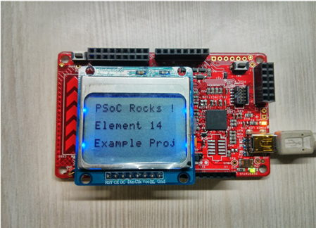


image


Test Your Project:


Connect your screen and program the Pioneer kit. See the screen display the example text and images.


image


I hope this example can help you in your design.


Best,

Matt

Attachments:
5732.Project Images.zip
imagePCD8544 datasheet.pdf
Nokia5110 LCD Interface.cywrk.Archive03.zip
  • Sign in to reply
  • Cancel

Top Replies

  • chr1sg75
    chr1sg75 over 5 years ago in reply to koudelad +1
    Hi David, Thanks for taking the time to reply. Glad to see the forum is still alive. I have dug out an old BitScope, so I am in the process of debugging the signal lines. For what it's worth, I can answer…
  • charrua
    charrua over 11 years ago in reply to dougw

    Done that.


    Besides the changing of the pinout (mine is different from the one in the project) it wokrs ok!


    Thank you for the files and the help.


    Luis

    • Cancel
    • Vote Up 0 Vote Down
    • Sign in to reply
    • Cancel
  • Twistx77
    Twistx77 over 11 years ago

    Hi Everyone,


    I have ported a better library for the Nokia LCD to the PSoC Pionner. It will probably work with no problems with a PSoC 3 or 5. It is using bit bang at the moment to communicate with the module but I might add the SPI hardware configuration later. For now I will leave it like that so it is easy to use with PSoC3 and 5.

    The library ported is the glcd from Andy Gock (agock) (dot) (com). It is very good and you can add custom fonts using a third party software. You have more information in his github site.


    My example project is configured to be used with the Pioneer Kit but in the main.c file you have instructions to change it if the Pioneer Kit is not used. To use it just program the Pioneer and press one of the segments of the capacitive slider to select the each demo. (You have to reset the device to change demo).


    If anyone have any question just look for Twistx77 in Google and you will easily get a hold of me.


    Attached is the project.


    You don't have permission to edit metadata of this video.
    Edit media
    x
    image
    Upload Preview
    image

    Attachments:
    Demo glcd PSoC4 Pioneer Kit.cywrk.Archive01.zip
    • Cancel
    • Vote Up 0 Vote Down
    • Sign in to reply
    • Cancel
  • ronniejk
    ronniejk over 9 years ago in reply to dougw

    Hello Douglas,

    This is what CyPin datasheet says about current.

    Current – The drive current selection determines the maximum nominal logic level current

    required for a specific pin. Pins can supply more current at the cost of logic level

    compliance or can have a maximum value that is less than listed, based on system

    voltages. See the device datasheet for more details on drive currents.

      4mA source, 8mA sink – Default

      4mA source, 25mA sink – Requires SIO


    So in case of a PSOC4 Pioneer kit  CY8CKIT-042CY8CKIT-042 what is the maximum current I can source safely if I don't worry about voltage level is 10mA a possibility

    My LCD seems to be using around 10mA and 3.3V hence the question.

    • Cancel
    • Vote Up 0 Vote Down
    • Sign in to reply
    • Cancel
  • dougw
    dougw over 9 years ago in reply to ronniejk

    It may depend on what voltage you need, but 10 ma from an output rated at 4 ma is probably too much to hope for. If you really can't add an external FET you might consider using 3 pins tied together. Since the output voltage will sag if more than 4 ma are drawn, the 3 outputs will share current as long as they are switched at the same time.

    • Cancel
    • Vote Up 0 Vote Down
    • Sign in to reply
    • Cancel
  • ronniejk
    ronniejk over 8 years ago

    The attached code, can't compile.


    We are maintaining PSoC Creator  3.0 SP2 (3.0.0.3140) environment to be compatible with the legacy code we have. So we can not update the creator. Attached is the environment we use. We also have compatible   CY8CKIT-042CY8CKIT-042 PSoC 4 Pioneer Kit Rev*B installed.


    It first gives this cy_boot error "Error in component: cy_boot. The cy_boot_v3_40 component (cy_boot) is an Obsolete component. It is no longer recommended for use and should be replaced with a production version of the component (or an alternative implementation)."


    And once I update the components, it comes back with 70 errors. Most are like "Analog terminal "P2_0_A0.analog_0" on PSoC_4_Pioneer_Kit is unconnected."


    Is there anyway to resolve this without updating to Creator 3.2?

    Attachments:
    PSOC_ENV.txt.zip
    • Cancel
    • Vote Up 0 Vote Down
    • Sign in to reply
    • Cancel
  • chr1sg75
    chr1sg75 over 5 years ago

    I know this is an old post, but hopefully someone is still listening :-)

    I have tried to get this to work on the Cypress PSoC 4 Bluetooth BLE module (CY8CKIT-143A) but am having no luck.

    Obviously, I have changed the device in the project to the correct one, but apart from that, should I worry about anything else?

    I used the following pins (and updated the project to reflect these changes)

    RST -> P3.7

    CE -> P3.5

    DC -> P3.3

    DIN -> P3.1

    CLK -> P5.1

    VCC -> P5.0

    GND -> P2.5

    (I didn't connect the BL pin because I don't need the backlight)

    Any suggestions why I'm getting nothing on screen?

    Cheers,

    Chris

    • Cancel
    • Vote Up 0 Vote Down
    • Sign in to reply
    • Cancel
  • koudelad
    koudelad over 5 years ago in reply to chr1sg75

    Hello,


    I guess many of us won't have exactly the same HW setup, so I would recommend a few things:

    1) Double check wiring, both data and power: if you apply voltage to an LCD, it usually brightens or darkens - does this happen? (Did the LCD work in any other application?)

    2) Does your PSoC program really run? Do you have a debugger? Does the code execute or is stuck somewhere? If you don't have a debugger, can you create a demo to draw a pixel, light an LED (or toggle any other pin you have free) or similar to verify it is running?

    3) If someone has similar HW, it would help if you posted a buildable project archive from PSoC Creator.


    If you don't find help here, post your question to a Cypress Developer Community: https://community.cypress.com/welcome


    David

    • Cancel
    • Vote Up 0 Vote Down
    • Sign in to reply
    • Cancel
  • chr1sg75
    chr1sg75 over 5 years ago in reply to koudelad

    Hi David,

    Thanks for taking the time to reply. Glad to see the forum is still alive.

    I have dug out an old BitScope, so I am in the process of debugging the signal lines.

    For what it's worth, I can answer some of your suggestions:

    - The backlight illuminates when the LCD is powered (although BL needs to be pulled low).

    - It's the first time I've used the LCD, so I haven't seen anything on the screen previously. I guess it could be dead.

    - The PSoC definitely runs

    - I will post my archive if I fail to diagnose with the 'scope

    And of course, if I figure out what is going wrong, I'll post an update.

    Cheers

    • Cancel
    • Vote Up +1 Vote Down
    • Sign in to reply
    • Cancel
  • chr1sg75
    chr1sg75 over 5 years ago in reply to chr1sg75

    Update:

    I have 'scoped the signal lines and things appear to behaving as I would expect.

    I did wonder why the CE line is not set high during initialisation, but I guess if it doesn't matter as long as the LCD is reset properly.

    I will upload the archive and perhaps someone can tell me what I might be doing wrong. Also, some photos to show the hardware setup.

    p.s. I added a Temp signal so that I could have a known line to trigger the 'scope.


    imageimage

    • Cancel
    • Vote Up 0 Vote Down
    • Sign in to reply
    • Cancel
<
element14 Community

element14 is the first online community specifically for engineers. Connect with your peers and get expert answers to your questions.

  • Members
  • Learn
  • Technologies
  • Challenges & Projects
  • Products
  • Store
  • About Us
  • Feedback & Support
  • FAQs
  • Terms of Use
  • Privacy Policy
  • Legal and Copyright Notices
  • Sitemap
  • Cookies

An Avnet Company © 2025 Premier Farnell Limited. All Rights Reserved.

Premier Farnell Ltd, registered in England and Wales (no 00876412), registered office: Farnell House, Forge Lane, Leeds LS12 2NE.

ICP 备案号 10220084.

Follow element14

  • X
  • Facebook
  • linkedin
  • YouTube