


Introduction
This blog post covers a quick project to build-you-own USB Serial Adapter. It can be used for connecting up computers to other computers or microcontrollers.
Note: For more modern USB-C circuits, see either Building a USB-C USB-UART Board and/or CH340: Building Yet Another USB-C to UART Adapter Board
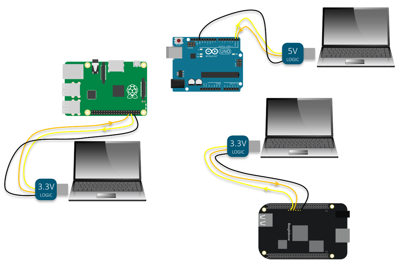
Some USB-UART scenarios are shown in the diagram, connecting up the Raspberry Pi or Arduino or BeagleBone Black to a laptop’s serial port.
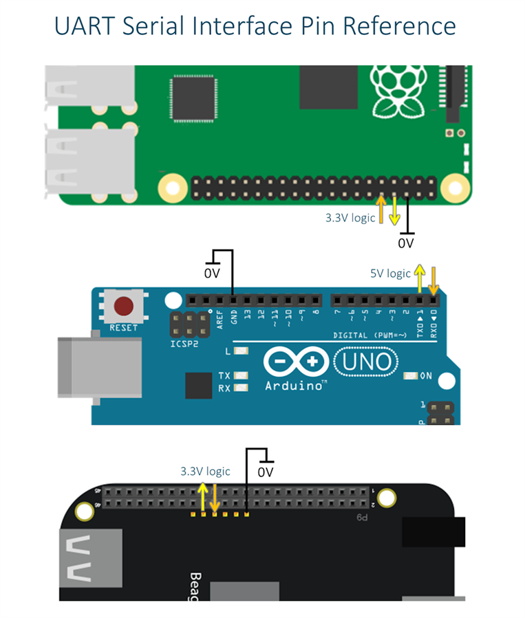
This diagram below (click to zoom) can be used as a general purpose reference for these boards, of the correct pins to wire up to any USB Serial Adapter, and signal directions are marked with arrows on the yellow and orange (board transmit and receive) wires. The black wire is 0V (Ground).
A zoomed-up diagram:

Ready-built USB Serial adapters are available from many vendors, but sometimes it is interesting to build-your-own. It could be integrated into a larger project for providing a USB interface for instance.
What is a USB Serial Adapter Needed For?
If you’ve ever purchased a single board computer (SBC) such as the BeagleBone Black or Raspberry Pi then you’ll know that SBCs usually have a ‘console’ connection in the form of a pair of serial signals (yellow and orange wires in the diagram earlier) known as Universal Asynchronous Receiver/Transmitter (UART) serial signals. These two signals along with a ground wire are usually brought out to header pins. Often these signals are referred to as just a Serial Interface, which is how it will be referred to for the rest of this post. It is not a great term, since ‘serial’ can refer to many types of interfaces, so specifically the capitalised Serial Interface terminology will be used in this post to refer to the UART serial interface.
The console provides a way to access the Linux command line from other hardware (usually a PC) instead of using a keyboard and mouse connected to the SBC.
The Serial Interface is very similar to the RS232 interface that was available on PCs. The major difference is that the Serial Interface often has relatively low voltages on the pins, and the RS232 interface has high voltages and they are not compatible without performing voltage level conversion.
Typically Serial Interface signals are directly connected to digital circuitry and therefore have a low (approximately 0V) logic level to signify binary ‘0’. The logic high level is a positive voltage approximately 3.3V, 5V, or 1.8V. It is dependent on the particular SBC but the three mentioned are most common. The Arduino uses 5V levels. The Raspberry Pi and BeagleBone Black use 3.3V levels.
The console is of interest because it is a very simple interface and therefore there is less to go wrong when troubleshooting SBCs. The interface is so simple that even low cost microcontroller boards such as the Arduino have such an interface. USB Keyboard and monitor connections are far more complex to implement.
What Is Out There?
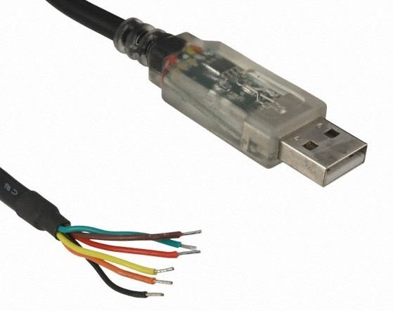
One convenient ready-made USB Serial Adapter is the FTDI TTL-232RG-VIP-WEFTDI TTL-232RG-VIP-WE. It comes as a USB shaped device with six bare wires. The yellow, orange and black wires can be connected up as shown in the earlier diagram. The red wire is connected to 1.8, 3.3 or 5V depending on the required logic levels. This provides a lot of flexibility! The remainder two wires (brown and green) are left disconnected.
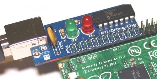
Often USB Serial Adapters can have different names. An example is the ‘Debug Clip’ which is no different to any other USB Serial Adapter except that it is a push-fit onto the Raspberry Pi and is intended for 3.3V logic levels (to match the Raspberry Pi Serial Interface). It may be convenient if you only use the Raspberry Pi, but sometimes a more generic solution is preferred.
Here is another one showing that sometimes the detail is subtle; it is called a ‘USB to TTL Serial Cable’ incorrectly unfortunately. TTL refers to 5V logic levels, yet this product is designed to interface to 3.3V Serial Interfaces for devices such as the Raspberry Pi. The product would be suitable for other 3.3V boards too such as the BeagleBone Black, but not useful for the Arduino which needs 5V logic levels.

Out of the three if I had to choose one, it would be the FTDI cable because it provides the most flexibility.
Building Your Own
Several manufacturers such as FTDI, Microchip and Silicon Labs produce integrated circuits (ICs) intended for USB Serial adapters. The project here uses the Microchip MCP2221Microchip MCP2221 which coincidentally is the same part used in the ‘Debug Clip’ mentioned earlier.
For some additional flexibility this project will have switchable 5V and 3.3V logic levels.
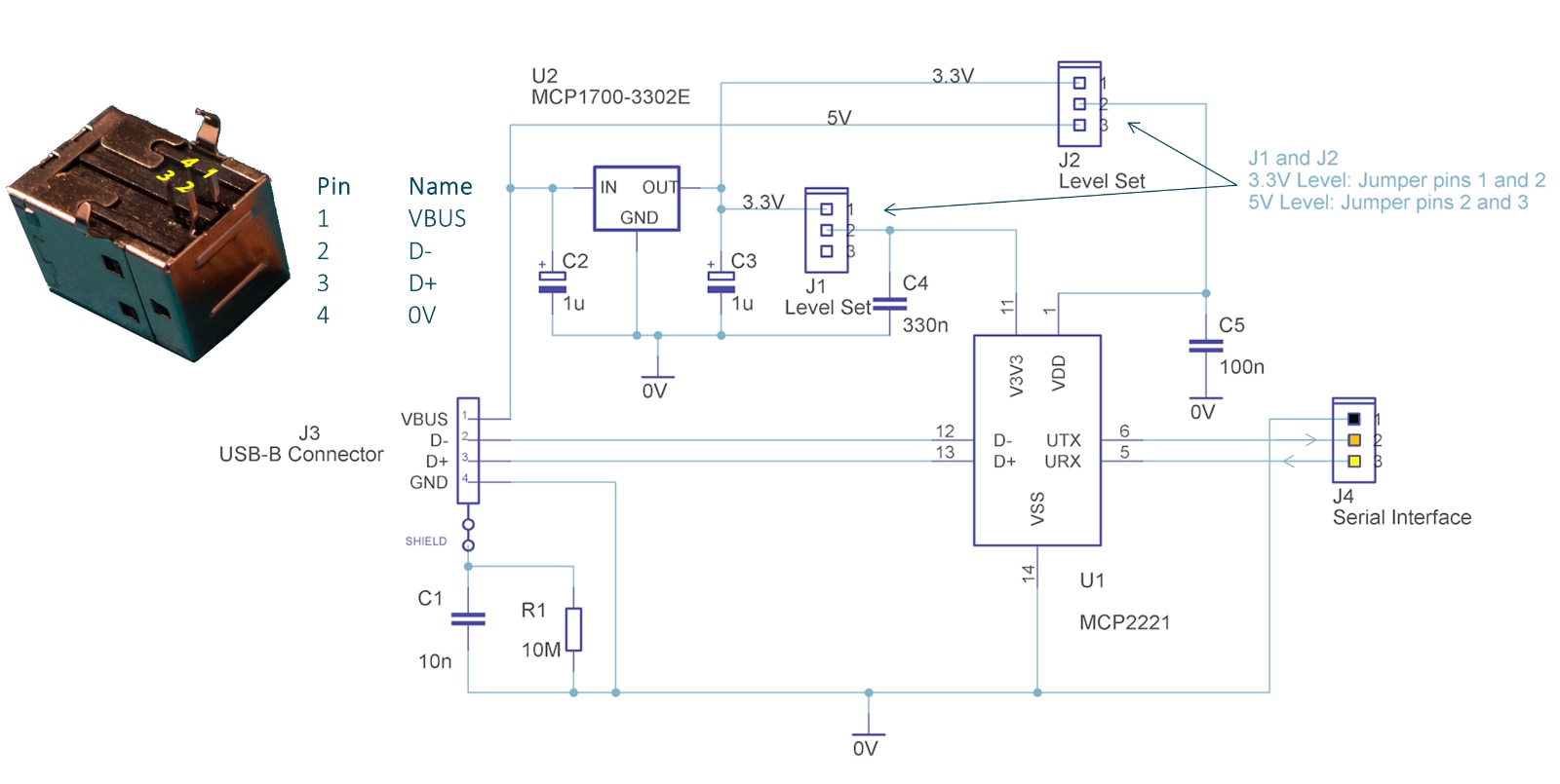
The circuit is very simple and can be constructed in a few hours. All parts are through-hole. Here is the circuit diagram. It consists of the MCP2221 MCP2221 of course, and also a 3.3V regulator3.3V regulator. A couple of 3-pin SIL header pins and jumpers are used to select between 3.3V and 5V modes.
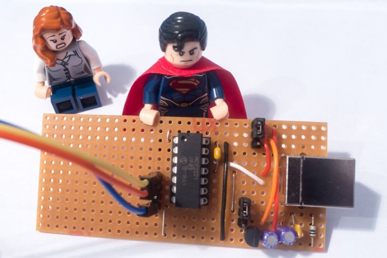
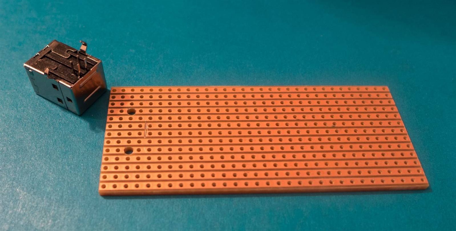
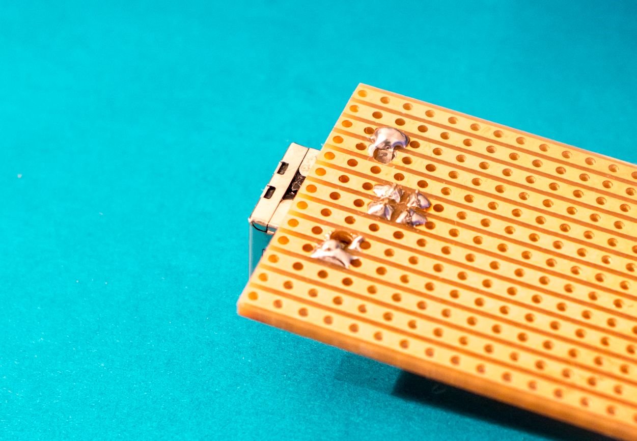
First off, grab some stripboard and make a couple of holes to allow the large USB Type-B connector to fit. Also some tracks need to be cut (use a sharp knife such as a scalpel) as shown. Use a multimeter to confirm that there are no fragments of copper causing shorts.
The shield lugs are bent over and soldered down.
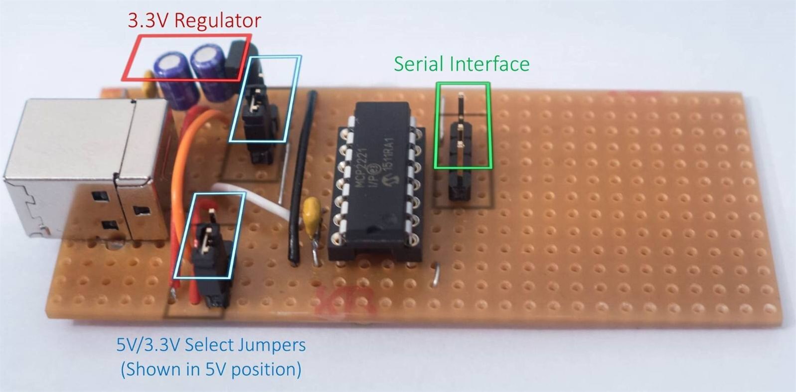
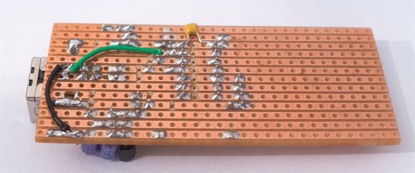
The photo below shows the completed board, underside view. I soldered a few wires and a capacitor on the underside to make it easier. Note that the D+ and D- wires between the USB connector and the MCP2221 need to be kept fairly short.
Using the Adapter
Once the circuit is complete, plug it into the PC (I used Windows 7 here; the procedure may vary slightly for Mac and Linux).
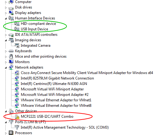
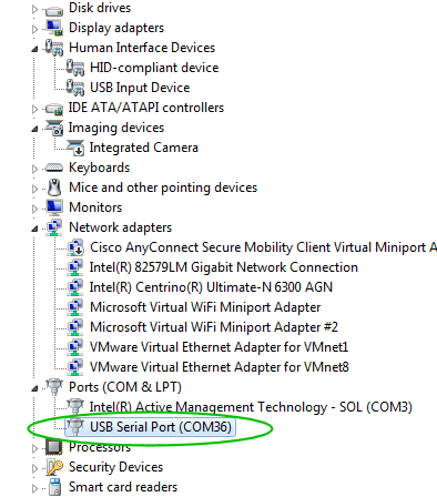
Using Windows it was possible to see in the Device Manager that a driver was not found (see the red circled device):
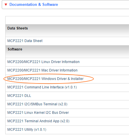
The next step was to go to the Microchip website and download the appropriate drivers and unzip the driver package.
In the Windows Device Manager the device that had not installed (circled in red in the earlier screenshot) was right-clicked to install a driver and the folder with the downloaded driver was selected. Success!
Now it can be used in the usual manner with terminal software such as PuTTY.
Next Steps / Ideas
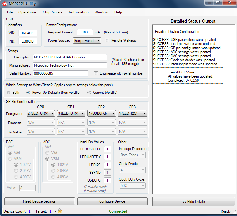
The MCP2221 is actually quite flexible; it is possible to wire up LEDs for status information or have general purpose input/output (GPIO) connections or even control I2C devices. This wasn’t explored – I was only interested in the USB Serial adapter functionality. There is a Windows based utility that can be used to configure the MCP2221, it looks like this:
If desired, other bits of functionality could be soldered to the stripboard; for example an RS232 interface. It would also be nice to create a small PCB and build a couple of these USB Serial adapters, since one is sometimes not enough.
Summary
The MCP2221 makes light work of implementing a USB Serial Interface. It was extremely easy to build up this project and will be useful for working with 3.3V logic level interfaces on boards such as the Raspberry Pi and BeagleBone Black, and 5V logic on other boards such as Arduino.
The reference diagram at the top of this blog post may be handy to bookmark, it shows the direction of Serial Interface signals in coloured arrows on the yellow and orange wires (not all diagrams make this clear).
Top Comments