element14 Community
element14 Community
    Register Log In
  • Site
  • Search
  • Log In Register
  • About Us
  • Community Hub
    Community Hub
    • What's New on element14
    • Feedback and Support
    • Benefits of Membership
    • Personal Blogs
    • Members Area
    • Achievement Levels
  • Learn
    Learn
    • Ask an Expert
    • eBooks
    • element14 presents
    • Learning Center
    • Tech Spotlight
    • STEM Academy
    • Webinars, Training and Events
    • Learning Groups
  • Technologies
    Technologies
    • 3D Printing
    • FPGA
    • Industrial Automation
    • Internet of Things
    • Power & Energy
    • Sensors
    • Technology Groups
  • Challenges & Projects
    Challenges & Projects
    • Design Challenges
    • element14 presents Projects
    • Project14
    • Arduino Projects
    • Raspberry Pi Projects
    • Project Groups
  • Products
    Products
    • Arduino
    • Avnet Boards Community
    • Dev Tools
    • Manufacturers
    • Multicomp Pro
    • Product Groups
    • Raspberry Pi
    • RoadTests & Reviews
  • Store
    Store
    • Visit Your Store
    • Choose another store...
      • Europe
      •  Austria (German)
      •  Belgium (Dutch, French)
      •  Bulgaria (Bulgarian)
      •  Czech Republic (Czech)
      •  Denmark (Danish)
      •  Estonia (Estonian)
      •  Finland (Finnish)
      •  France (French)
      •  Germany (German)
      •  Hungary (Hungarian)
      •  Ireland
      •  Israel
      •  Italy (Italian)
      •  Latvia (Latvian)
      •  
      •  Lithuania (Lithuanian)
      •  Netherlands (Dutch)
      •  Norway (Norwegian)
      •  Poland (Polish)
      •  Portugal (Portuguese)
      •  Romania (Romanian)
      •  Russia (Russian)
      •  Slovakia (Slovak)
      •  Slovenia (Slovenian)
      •  Spain (Spanish)
      •  Sweden (Swedish)
      •  Switzerland(German, French)
      •  Turkey (Turkish)
      •  United Kingdom
      • Asia Pacific
      •  Australia
      •  China
      •  Hong Kong
      •  India
      •  Korea (Korean)
      •  Malaysia
      •  New Zealand
      •  Philippines
      •  Singapore
      •  Taiwan
      •  Thailand (Thai)
      • Americas
      •  Brazil (Portuguese)
      •  Canada
      •  Mexico (Spanish)
      •  United States
      Can't find the country/region you're looking for? Visit our export site or find a local distributor.
  • Translate
  • Profile
  • Settings
BeagleBoard
  • Products
  • Dev Tools
  • Single-Board Computers
  • BeagleBoard
  • More
  • Cancel
BeagleBoard
Blog BeagleBone Control Stepper Motors with PRU - Part 2: Test Driving Outputs
  • Blog
  • Forum
  • Documents
  • Quiz
  • Polls
  • Files
  • Members
  • Mentions
  • Sub-Groups
  • Tags
  • More
  • Cancel
  • New
Join BeagleBoard to participate - click to join for free!
  • Share
  • More
  • Cancel
Group Actions
  • Group RSS
  • More
  • Cancel
Engagement
  • Author Author: Jan Cumps
  • Date Created: 24 Jul 2019 7:42 PM Date Created
  • Views 3971 views
  • Likes 9 likes
  • Comments 7 comments
  • stepper_motor
  • pru
  • BeagleBone
Related
Recommended

BeagleBone Control Stepper Motors with PRU - Part 2: Test Driving Outputs

Jan Cumps
Jan Cumps
24 Jul 2019

I'm trying here is to let the real-time units of the BeagleBone generate the signals for a stepper motor.

In this post: control two output pins from PRU and Linux

image


The PRU will have to drive two pins when driving the stepper motor.

One for the direction of rotation. The other for the step pulses.

I'll try here to send the PRU a number of steps, and a flag to give the direction.

The PRU should then drive the DIR pin (high or low based on the parameter) and pulse the STEP pin the requested number of times.


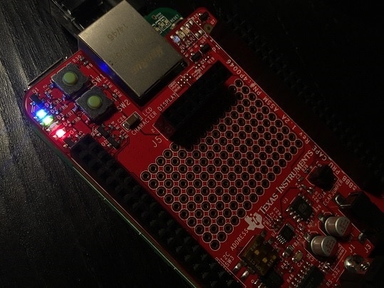
I'm selecting PRU GPIO pins 29 and 31 - because I have a cape that has LEDs on these pins that make it easy to see the effect.

But any PRU accessible GPIO pins can be used.


MUX Outputs for PRU


There are several ways you can define the pin mux. I'm using the Linux driver to do that.

These are the two pins I'm using:

  • PR1_PRU0_GPO0: P9_31 (blue LED, symbolically represents the DIR signal)
  • PR1_PRU0_GPO1: P9_29 (green LED, represents the STEP signal)


image

image source: modified from seeed wiki for the BB green


These Linux commands reserve them as PRU controlled output pins:

config-pin P9_31 pruout
config-pin P9_29 pruout


The PRU can now address them and drive them high and low.


When finished at the end of the program, best assign them back to their default muxing. Else the PRU driver complains after reboot.

config-pin P9_31 default
config-pin P9_29 default


Very likely there's a better way to do this (overlay?). If you know how, put it in the comments please.


Simple PRU Program to Drive the Pins


My code is based on TI's example program LAB 6: Blinking LEDs with RPMsg from Linux User Space.

The TI copyright is taken over. I don't claim any additional rights for my changes. They are free for any purpose.


// Based on LAB 6: Blinking LEDs with RPMsg from Linux User Space.
// http://processors.wiki.ti.com/index.php/PRU_Training:_Hands-on_Labs#LAB_6:_Blinking_LEDs_with_RPMsg_from_Linux_User_Space


/*
 * Copyright (C) 2016-2018 Texas Instruments Incorporated - http://www.ti.com/
....
 */


#include <stdint.h>
#include <stdio.h>
#include <ctype.h>
#include <pru_cfg.h>
#include <pru_intc.h>
#include <rsc_types.h>
#include <pru_rpmsg.h>
#include "resource_table_0.h"


Two PRU registers are used for the two pins and interrupts from + to Linux


volatile register uint32_t __R30;
volatile register uint32_t __R31;

/* Host-0 Interrupt sets bit 30 in register R31 */
#define HOST_INT ((uint32_t) 1 << 30)

/* The PRU-ICSS system events used for RPMsg are defined in the Linux device tree
 * PRU0 uses system event 16 (To ARM) and 17 (From ARM)
 * PRU1 uses system event 18 (To ARM) and 19 (From ARM)
 */
#define TO_ARM_HOST 16
#define FROM_ARM_HOST 17

#define DIR     0x0
#define STEP    0x1


Common parts to exchange info with Linux. Literally from TI's example:


/*
* Using the name 'rpmsg-pru' will probe the rpmsg_pru driver found
* at linux-x.y.z/drivers/rpmsg/rpmsg_pru.c
*/
#define CHAN_NAME "rpmsg-pru"
#define CHAN_DESC "Channel 30"
#define CHAN_PORT 30

/*
 * Used to make sure the Linux drivers are ready for RPMsg communication
 * Found at linux-x.y.z/include/uapi/linux/virtio_config.h
 */
#define VIRTIO_CONFIG_S_DRIVER_OK 4

uint8_t payload[RPMSG_MESSAGE_SIZE];

/*
 * main.c
 */
void main(void)
{
struct pru_rpmsg_transport transport;
uint16_t src, dst, len;
volatile uint8_t *status;

__R30 = 0x0;

/* Allow OCP master port access by the PRU so the PRU can read external memories */
CT_CFG.SYSCFG_bit.STANDBY_INIT = 0;

/* Clear the status of the PRU-ICSS system event that the ARM will use to 'kick' us */
CT_INTC.SICR_bit.STS_CLR_IDX = FROM_ARM_HOST;

/* Make sure the Linux drivers are ready for RPMsg communication */
status = &resourceTable.rpmsg_vdev.status;
while (!(*status & VIRTIO_CONFIG_S_DRIVER_OK));

/* Initialize the RPMsg transport structure */
pru_rpmsg_init(&transport, &resourceTable.rpmsg_vring0, &resourceTable.rpmsg_vring1, TO_ARM_HOST, FROM_ARM_HOST);

/* Create the RPMsg channel between the PRU and ARM user space using the transport structure. */
while (pru_rpmsg_channel(RPMSG_NS_CREATE, &transport, CHAN_NAME, CHAN_DESC, CHAN_PORT) != PRU_RPMSG_SUCCESS);
while (1) {
/* Check bit 30 of register R31 to see if the ARM has kicked us */
if (__R31 & HOST_INT) {
/* Clear the event status */
CT_INTC.SICR_bit.STS_CLR_IDX = FROM_ARM_HOST;


Now my part. I expect a string of characters from Linux.

Position 1 is the direction ('0' or '1').

All others are a number of steps, and should all be digits.


Example:

1458: Set the DIR pin high, pulse 458 times.

06: Set the DIR pin low, pulse 6 times.


First we check the direction and drive the pin accordingly:


/* Receive all available messages, multiple messages can be sent per kick */
while (pru_rpmsg_receive(&transport, &src, &dst, payload, &len) == PRU_RPMSG_SUCCESS) {
    if (len < 2) { // at least directory and 1 bit of counts
        break;
    }

    // fist position is direction. If '0', then clear DIR bit, else set dir bit
    if (payload[0] == '0') {
                    __R30 &= ~(1UL << DIR);
    } else {
                    __R30 |= 1UL << DIR;
    }


Then calculate the number of pulses.

I parse each character in the argument and give it the right weight by using this formula (the first, most siginificant digit is at index 1):

digit * 10 pow (total length - 2 - position)


   // get the number of pulses
    int i;
    uint32_t pulses = 0U;
    for (i = 1; i < len; i++) {
        if (isdigit(payload[i])) {
            pulses += ((payload[i] - '0') * opt_int_pow(len - 2 - i));
        }
    }


And then toggle the step line twice for each pulse, because a pulse has two edges)

    // toggle STEP twice the pulse count (a pulse is two toggles)
    for (i = 0; i < pulses * 2; i++) {
        __R30 ^= 1UL << STEP;  // can be optimised if I constant the right operator
                    __delay_cycles(600000); // Intrinsic method delay
    }
   }
  }
 }
}


Because the standard pow() function does not fit in the PRU's memory, I borrowed one from stackowerflow:

static int opt_int_pow(int n)
{
    int r = 1;
    const int x = 10;
    while (n)
    {
        if (n & 1) 
        {
           r *= x;
           n--;
        }
        else
        {
            r *= x * x;
            n -= 2;
        }
    }
    return r; 
}


Compile, then copy the executable to the BB. I moved it to /home/debian/bin


In Linux, execute these commands to drive the DIR high and run 20 pulses:


sudo -i

config-pin P9_31 pruout
config-pin P9_29 pruout

cp /home/debian/bin/bb_PRU_STEPPER.out /lib/firmware/bb_PRU_STEPPER.out

echo 'bb_PRU_STEPPER.out' > /sys/class/remoteproc/remoteproc1/firmware

echo 'start' > /sys/class/remoteproc/remoteproc1/state

echo "120" > /dev/rpmsg_pru30

echo 'stop' > /sys/class/remoteproc/remoteproc1/state

config-pin P9_31 default
config-pin P9_29 default

exit


It works!


Code Composer Studio project attached.

You need to download TI's LABs, they contain some dependencies we need.

In the project's properties, adapt the variable PRU_SOFTWARE_SUPPORT_PACKAGE to the home location where you saved the LABs.

image


Related blog:
BeagleBone Control Stepper Motors with PRU - Part 1: Intentions
BeagleBone Control Stepper Motors with PRU - Part 2: Test Driving Outputs
BeagleBone: Enable SPI with Overlay and from Command Line
BeagleBone Control Stepper Motors with PRU - Part 3: Hardware Provisioning and Wiring
BeagleBone Control Stepper Motors with PRU - Part 4: SPI Setup
BeagleBone Control Stepper Motors with PRU - Part 5: It Works
Attachments:
bb_PRU_STEPPER20190724.zip
  • Sign in to reply

Top Comments

  • Jan Cumps
    Jan Cumps over 6 years ago +2
    Here's a first capture. Command executed: echo "1150" > /dev/rpmsg_pru30 First char is '1'. It tells the PRU to dive the DIR pin high. The remainder is '150', telling the PRU to create a train of 150 pulses…
  • Jan Cumps
    Jan Cumps over 6 years ago in reply to Jan Cumps +2
    The plot below shows the time the PRU needs between two commands. I've sent these two commands, at the same time: echo "030000" > /dev/rpmsg_pru30 echo "130000" > /dev/rpmsg_pru30 Generate a 30000 pulse…
  • DAB
    DAB over 6 years ago +1
    Nice walk through of the Linux driver software. DAB
  • Jan Cumps
    Jan Cumps over 6 years ago

    Example C program that sends data to the PRU: https://git.ti.com/pru-software-support-package/pru-software-support-package/blobs/master/examples/am335x/PRU_ADC_onChip…


    It uses the same mechanism as Linux command line, using the character device /dev/rpmsg_pru30.

    • Cancel
    • Vote Up +1 Vote Down
    • Sign in to reply
    • More
    • Cancel
  • Jan Cumps
    Jan Cumps over 6 years ago in reply to Jan Cumps

    version of the code before (trying to) switch to timer controlled program flow


    https://gist.github.com/jancumps/ee9482dd27856c823ddcf505830dece4

    • Cancel
    • Vote Up 0 Vote Down
    • Sign in to reply
    • More
    • Cancel
  • Jan Cumps
    Jan Cumps over 6 years ago in reply to Jan Cumps

    One option to make a smooth stepper motor profile is with an acceleration and deceleration part at begin and end.

    The acceleration from start speed to requested speed (and the deceleration at the end) can be calculated and set during the execution (I have example code for a few microcontrollers)


    I'm trying to do that wit the PRU's internal timer. First babystep is to see if I can make the timer work (answer: yes): BeagleBone PRU - Timer Functionality

    • Cancel
    • Vote Up 0 Vote Down
    • Sign in to reply
    • More
    • Cancel
  • Jan Cumps
    Jan Cumps over 6 years ago in reply to Jan Cumps

    The plot below shows the time the PRU needs between two commands.

    I've sent these two commands, at the same time:

    echo "030000" > /dev/rpmsg_pru30
    echo "130000" > /dev/rpmsg_pru30


    Generate a 30000 pulse train, then a 30000 train with direction reversed.

    Because Linux has sent the commands to the PRU way before the first 30000 pulses finished, we have virtually no overhead from the OS in this image. Everything on that side is done.


    The time between the last pulse of the first train (end of burst in the yellow trace) and change of direction (ramp in the blue trace) is what it takes the PRU to

    • retrieve the 2nd command from the queue
    • parse the first character of that command (the direction)
    • a tiny chunk relating to return to the top of the loop and evaluate the loop condition


    The time between the change of direction and the second train start (start of 2nd burst in the yellow trace) is the time needed to parse the remainder of the command and calculate the number of toggles needed to generate the right number of pulses.


    image


    If you can keep the queue entertained, there's approx. 6 µs between commands.

    I expect that this time becomes longer when I start calculating a smooth ramp up and down.

    The jitter during the run of one command is low. Because the PRU execution time is deterministic, it's basically the jitter from the specs.

    But if you shoot a movement as two commands (say: 100 steps then 20 steps), you'd get that 6µs as jitter.

    In the big scheme of things, it 'll be ok.


    Let's say I want to run the motor at 1200 RPM (very fast for a stepper).

    That's 20 rounds per second

    The motor has 200 steps per round (my motor, when not microstepping).

    I'd have to create 20 * 200 = 400 pulses per second, 400 Hz.

    At 400 Hz, the duration of one pulse is 1/400 = 0.0025 s

    That's 2500 µs. The 6 µs in one of those pulses would be a 0.24% jitter at the time the PRU switches between commands (+ PRU jitter from its specs).

    (I can't be trusted with math).

    • Cancel
    • Vote Up +2 Vote Down
    • Sign in to reply
    • More
    • Cancel
  • Jan Cumps
    Jan Cumps over 6 years ago

    Here's a first capture.

    Command executed:

    echo "1150" > /dev/rpmsg_pru30


    First char is '1'. It tells the PRU to dive the DIR pin high.

    The remainder is '150', telling the PRU to create a train of 150 pulses

    The main ARM controller only spends time when submitting the command, almost nothing.

    Even if you tell the PRU to generate a few thousand pulses, the time spent in Linux is a few miliseconds.

    You can keep on submitting commands from Linux while the previous command is still executing. They are queued and the PRU picks them up 1 by 1.


    image


    I removed the wait time, so this is close to the maximum frequency I can achieve.

    The code isn't optimised. I could eek out some clock ticks by easy optimisations - but at the cost of readability.

    It's frequency is 6.7 MHz. I don't think optimisation is needed for a stepper motor.


    Below capture is when I execute the command:

    echo "04" > /dev/rpmsg_pru30


    It drives DIR low and generates 4 pulses. Ideal to get a few pulses on the screen in good resolution.

    I've added the frequency at the bottom of the screen.


    image

    • Cancel
    • Vote Up +2 Vote Down
    • Sign in to reply
    • More
    • Cancel
>
element14 Community

element14 is the first online community specifically for engineers. Connect with your peers and get expert answers to your questions.

  • Members
  • Learn
  • Technologies
  • Challenges & Projects
  • Products
  • Store
  • About Us
  • Feedback & Support
  • FAQs
  • Terms of Use
  • Privacy Policy
  • Legal and Copyright Notices
  • Sitemap
  • Cookies

An Avnet Company © 2025 Premier Farnell Limited. All Rights Reserved.

Premier Farnell Ltd, registered in England and Wales (no 00876412), registered office: Farnell House, Forge Lane, Leeds LS12 2NE.

ICP 备案号 10220084.

Follow element14

  • X
  • Facebook
  • linkedin
  • YouTube