


I'm trying here is to let the real-time units of the BeagleBone generate the signals for a stepper motor. In this post: configure the stepper motor driver via the SPI interface.
|
This is virtually the same code as used in my Hercules real-time stepper driver project.
I'm using the DRV8711 SPI interface to set its registers. They determine the driver's behaviour.
The only difference is that I now use the BB's Linux SPI interface to talk to it instead of the Hercules SPI module.
I've made an executable in C. It sets the registers, then exits.
The program flow is extremely simple:
int main(int argc, char *argv[]) {
    int fd = initialize();
    WriteAllRegisters(fd);
    finalize(fd);
    return 0;
}
Declaration of constants and variables (the code with the struct structures is in the attached full CCS project).
// DRV8711 Registers
struct CTRL_Register     G_CTRL_REG;
struct TORQUE_Register   G_TORQUE_REG;
struct OFF_Register      G_OFF_REG;
struct BLANK_Register    G_BLANK_REG;
struct DECAY_Register    G_DECAY_REG;
struct STALL_Register    G_STALL_REG;
struct DRIVE_Register    G_DRIVE_REG;
struct STATUS_Register   G_STATUS_REG;

// Register Access
#define REGWRITE    0x0000

static const char *device = "/dev/spidev1.0";
static uint8_t mode;
static uint8_t bits = 16;
static uint32_t speed = 500000;
static uint16_t delay;
The initialize() function sets SPI interface and initialises register settings.
Attention: the DRV8711 uses the uncommon CS High mode. The IC listens to SPI commands only when the CS line is high.
It took me a while to find how to do that on a BB.
You have to set the mode accordingly:
mode |= SPI_CS_HIGH;
int initialize() {
    int ret = 0;
    int fd;

    fd = open(device, O_RDWR);
    if (fd < 0)
        pabort("can't open device");

    /*
     * spi mode
     */
    mode |= SPI_CS_HIGH; // attention, the DRV8711 uses CS high
    ret = ioctl(fd, SPI_IOC_WR_MODE, &mode);
    if (ret == -1)
        pabort("can't set spi mode");

    ret = ioctl(fd, SPI_IOC_RD_MODE, &mode);
    if (ret == -1)
        pabort("can't get spi mode");

    /*
     * bits per word
     */
    ret = ioctl(fd, SPI_IOC_WR_BITS_PER_WORD, &bits);
    if (ret == -1)
        pabort("can't set bits per word");

    ret = ioctl(fd, SPI_IOC_RD_BITS_PER_WORD, &bits);
    if (ret == -1)
        pabort("can't get bits per word");

    /*
     * max speed hz
     */
    ret = ioctl(fd, SPI_IOC_WR_MAX_SPEED_HZ, &speed);
    if (ret == -1)
        pabort("can't set max speed hz");

    ret = ioctl(fd, SPI_IOC_RD_MAX_SPEED_HZ, &speed);
    if (ret == -1)
        pabort("can't get max speed hz");

    printf("spi mode: %d\n", mode);
    printf("bits per word: %d\n", bits);
    printf("max speed: %d Hz (%d KHz)\n", speed, speed/1000);

    // drv8711
    // Set Default Register Settings
    // CTRL Register
    G_CTRL_REG.Address     = 0x0000;
    G_CTRL_REG.DTIME     = 0x0003;
    G_CTRL_REG.ISGAIN     = 0x0003;
    G_CTRL_REG.EXSTALL     = 0x0000;
//     G_CTRL_REG.MODE     = 0x0003;  // in 8th steps
    G_CTRL_REG.MODE     = 0x0000; // in full steps
    G_CTRL_REG.RSTEP     = 0x0000;
    G_CTRL_REG.RDIR     = 0x0000;
    G_CTRL_REG.ENBL     = 0x0001;

    // TORQUE Register
    G_TORQUE_REG.Address = 0x0001;
    G_TORQUE_REG.SIMPLTH = 0x0000;
    G_TORQUE_REG.TORQUE  = 0x00BA;

    // OFF Register
    G_OFF_REG.Address     = 0x0002;
    G_OFF_REG.PWMMODE     = 0x0000;
    G_OFF_REG.TOFF         = 0x0030;

    // BLANK Register
    G_BLANK_REG.Address = 0x0003;
    G_BLANK_REG.ABT     = 0x0001;
    G_BLANK_REG.TBLANK     = 0x0008;


    // DECAY Register.
    G_DECAY_REG.Address = 0x0004;
    G_DECAY_REG.DECMOD  = 0x0003;
    G_DECAY_REG.TDECAY     = 0x0010;

    // STALL Register
    G_STALL_REG.Address = 0x0005;
    G_STALL_REG.VDIV     = 0x0003;
    G_STALL_REG.SDCNT     = 0x0003;
    G_STALL_REG.SDTHR     = 0x0040;

    // DRIVE Register
    G_DRIVE_REG.Address = 0x0006;
    G_DRIVE_REG.IDRIVEP = 0x0000;
    G_DRIVE_REG.IDRIVEN = 0x0000;
    G_DRIVE_REG.TDRIVEP = 0x0001;
    G_DRIVE_REG.TDRIVEN = 0x0001;
    G_DRIVE_REG.OCPDEG     = 0x0001;
    G_DRIVE_REG.OCPTH     = 0x0001;

    // STATUS Register
    G_STATUS_REG.Address = 0x0007;
    G_STATUS_REG.STDLAT  = 0x0000;
    G_STATUS_REG.STD     = 0x0000;
    G_STATUS_REG.UVLO    = 0x0000;
    G_STATUS_REG.BPDF    = 0x0000;
    G_STATUS_REG.APDF    = 0x0000;
    G_STATUS_REG.BOCP    = 0x0000;
    G_STATUS_REG.AOCP    = 0x0000;
    G_STATUS_REG.OTS     = 0x0000;

    return fd;
}
I should split up the BB SPI init and the DRV8711 settings initialisation. They are unrelated activities. Maybe later ...
Then all registers are written.
void WriteAllRegisters(int fd) {
    uint16_t data;

    // Write CTRL Register
    data = REGWRITE | (G_CTRL_REG.Address << 12) | (G_CTRL_REG.DTIME << 10) | (G_CTRL_REG.ISGAIN << 8) |(G_CTRL_REG.EXSTALL << 7) | (G_CTRL_REG.MODE << 3) | (G_CTRL_REG.RSTEP << 2) | (G_CTRL_REG.RDIR << 1) | (G_CTRL_REG.ENBL);
    SPI_DRV8711_Write(fd, data);

    // Write TORQUE Register
    data = REGWRITE | (G_TORQUE_REG.Address << 12) | (G_TORQUE_REG.SIMPLTH << 8) | G_TORQUE_REG.TORQUE;
    SPI_DRV8711_Write(fd, data);

    // Write OFF Register
    data = REGWRITE | (G_OFF_REG.Address << 12) | (G_OFF_REG.PWMMODE << 8) | G_OFF_REG.TOFF;
    SPI_DRV8711_Write(fd, data);

    // Write BLANK Register
    data = REGWRITE | (G_BLANK_REG.Address << 12) | (G_BLANK_REG.ABT << 8) | G_BLANK_REG.TBLANK;
    SPI_DRV8711_Write(fd, data);

    // Write DECAY Register
    data = REGWRITE | (G_DECAY_REG.Address << 12) | (G_DECAY_REG.DECMOD << 8) | G_DECAY_REG.TDECAY;
    SPI_DRV8711_Write(fd, data);

    // Write STALL Register
    data = REGWRITE | (G_STALL_REG.Address << 12) | (G_STALL_REG.VDIV << 10) | (G_STALL_REG.SDCNT << 8) | G_STALL_REG.SDTHR;
    SPI_DRV8711_Write(fd, data);

    // Write DRIVE Register
    data = REGWRITE | (G_DRIVE_REG.Address << 12) | (G_DRIVE_REG.IDRIVEP << 10) | (G_DRIVE_REG.IDRIVEN << 8) | (G_DRIVE_REG.TDRIVEP << 6) | (G_DRIVE_REG.TDRIVEN << 4) | (G_DRIVE_REG.OCPDEG << 2) | (G_DRIVE_REG.OCPTH);
    SPI_DRV8711_Write(fd, data);

    // Write STATUS Register
    data = REGWRITE | (G_STATUS_REG.Address << 12) | (G_STATUS_REG.STDLAT << 7) | (G_STATUS_REG.STD << 6) | (G_STATUS_REG.UVLO << 5) | (G_STATUS_REG.BPDF << 4) | (G_STATUS_REG.APDF << 3) | (G_STATUS_REG.BOCP << 2) | (G_STATUS_REG.AOCP << 1) | (G_STATUS_REG.OTS);
    SPI_DRV8711_Write(fd, data);
}
The only function I had to write myself was the method to write 16 bit fields over SPI on Linux. It's based on the code of this blog: BeagleBone: Enable SPI with Overlay and from Command Line.
void SPI_DRV8711_Write(int fd, uint16_t data) {
    int ret;
    uint16_t tx[] = {data};

    struct spi_ioc_transfer tr = {
        .tx_buf = (unsigned long)tx,
        .rx_buf = (unsigned long)NULL,
        .len = (sizeof(tx)/sizeof(*tx))*2,
        .delay_usecs = delay,
        .speed_hz = speed,
        .bits_per_word = bits,
    };

    ret = ioctl(fd, SPI_IOC_MESSAGE(1), &tr);
    if (ret < 1)
        pabort("can't send spi message");
}
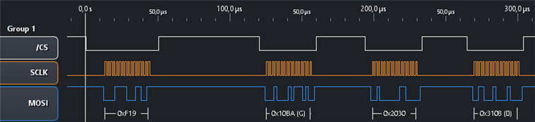
Here's the result captured by a logic analyser. The CS is not correct. The grab was made before I corrected the CS polarity.

I have the advantage that I've captured the traffic before on other microcontrollers. I can compare and validate.
The results are as expected.
Install the code to the bin directory in your home.
I'll now combine all previous work:
- initialise PRU pins
- run SPI init
- control reset and sleep pins via Linux command line
- run the PRU ocde to make the motor step
That's not a lot of work left. Hang on ...