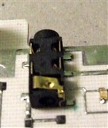
I am trying to create a footprint for this phono jack http://www.switchcraft.com/Drawings/35rapc__hn2_cd.pdf. And instead of pins that go through circular holes, it has tabs that go through rectangular holes. How do I do this in the footprint editor?
Also, the jack has five round pegs that appear to be for positioning. Is there a way to indicate this on the footprint in such a way that they will be drilled no matter where I place the jack (as opposed to putting holes on the board that would have to be re-positioned if I moved the jack)? I suppose that I could make them fake pads - so what if they get plated through? - but is there another way? Or maybe I will just ignore the pegs and let the piece sit 1 mm above the board. But I fear that the pegs are important for handling the stress of plugging a phono plug in and out all the time.
Finally, how are these pieces soldered in? Do the tabs have to be folded over before soldering? If so, this has impications for the board design too - there has to be a pad on the back side but only on one side of the hole.