element14 Community
element14 Community
    Register Log In
  • Site
  • Search
  • Log In Register
  • Community Hub
    Community Hub
    • What's New on element14
    • Feedback and Support
    • Benefits of Membership
    • Personal Blogs
    • Members Area
    • Achievement Levels
  • Learn
    Learn
    • Ask an Expert
    • eBooks
    • element14 presents
    • Learning Center
    • Tech Spotlight
    • STEM Academy
    • Webinars, Training and Events
    • Learning Groups
  • Technologies
    Technologies
    • 3D Printing
    • FPGA
    • Industrial Automation
    • Internet of Things
    • Power & Energy
    • Sensors
    • Technology Groups
  • Challenges & Projects
    Challenges & Projects
    • Design Challenges
    • element14 presents Projects
    • Project14
    • Arduino Projects
    • Raspberry Pi Projects
    • Project Groups
  • Products
    Products
    • Arduino
    • Avnet & Tria Boards Community
    • Dev Tools
    • Manufacturers
    • Multicomp Pro
    • Product Groups
    • Raspberry Pi
    • RoadTests & Reviews
  • About Us
  • Store
    Store
    • Visit Your Store
    • Choose another store...
      • Europe
      •  Austria (German)
      •  Belgium (Dutch, French)
      •  Bulgaria (Bulgarian)
      •  Czech Republic (Czech)
      •  Denmark (Danish)
      •  Estonia (Estonian)
      •  Finland (Finnish)
      •  France (French)
      •  Germany (German)
      •  Hungary (Hungarian)
      •  Ireland
      •  Israel
      •  Italy (Italian)
      •  Latvia (Latvian)
      •  
      •  Lithuania (Lithuanian)
      •  Netherlands (Dutch)
      •  Norway (Norwegian)
      •  Poland (Polish)
      •  Portugal (Portuguese)
      •  Romania (Romanian)
      •  Russia (Russian)
      •  Slovakia (Slovak)
      •  Slovenia (Slovenian)
      •  Spain (Spanish)
      •  Sweden (Swedish)
      •  Switzerland(German, French)
      •  Turkey (Turkish)
      •  United Kingdom
      • Asia Pacific
      •  Australia
      •  China
      •  Hong Kong
      •  India
      • Japan
      •  Korea (Korean)
      •  Malaysia
      •  New Zealand
      •  Philippines
      •  Singapore
      •  Taiwan
      •  Thailand (Thai)
      • Vietnam
      • Americas
      •  Brazil (Portuguese)
      •  Canada
      •  Mexico (Spanish)
      •  United States
      Can't find the country/region you're looking for? Visit our export site or find a local distributor.
  • Translate
  • Profile
  • Settings
Autodesk EAGLE
  • Products
  • More
Autodesk EAGLE
EAGLE User Support (English) How do I create holes and positions from imported DXF
  • Blog
  • Forum
  • Documents
  • Events
  • Polls
  • Files
  • Members
  • Mentions
  • Sub-Groups
  • Tags
  • More
  • Cancel
  • New
Join Autodesk EAGLE to participate - click to join for free!
Actions
  • Share
  • More
  • Cancel
Forum Thread Details
  • State Suggested Answer
  • Replies 21 replies
  • Answers 2 answers
  • Subscribers 180 subscribers
  • Views 4032 views
  • Users 0 members are here
  • cnc
  • holes
  • eagle pcb
  • led
  • layer
  • polygon
Related

How do I create holes and positions from imported DXF

shearder
shearder over 9 years ago

Hi All


I have a panel that i have designed which has switches, buttons, knobs (rotaries), LEDs and a LCD screen. I have imported the DXF version of this into Eagle on the dimension layer. I will machine a 300mmx300mm Double sided board.


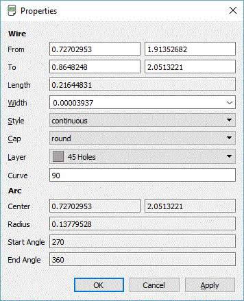
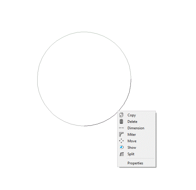
What i want to know: Some circles on the DXF are HOLES some are positions for LEDs.


How do i go about selecting a circle and making it a HOLE without redrawing a polygon and TRYING to align it. Also, how do i move other circles to a different layer for positioning of the LEDs?


Hope that makes sense.


Thanks in advance.

  • Sign in to reply
  • Cancel

Top Replies

  • autodeskguest
    autodeskguest over 9 years ago in reply to shearder +1 suggested
    Am 27.05.2016 um 12:46 schrieb Sean Hearder: That does make a lot of sense. So layer 45 isn't actually the drl layer for component holes but cut outs? I will try working with this over the weekend Thanks…
  • rachaelp
    rachaelp over 9 years ago +1 suggested
    Hi Sean, I posted this on your other thread in the suggest forum first then saw this so I am reposting in this thread which seems more live. Anyway, I thought this was an interesting query so decided to…
Parents
  • rachaelp
    0 rachaelp over 9 years ago

    Hi Sean,


    I posted this on your other thread in the suggest forum first then saw this so I am reposting in this thread which seems more live. Anyway, I thought this was an interesting query so decided to write a ULP to do this. Save the code below as circleToHole.ulp.


    #usage "en: Adds a hole at the location and size of the selected circle\n"

               "run circleToHole install - to install to the boards context menu"


    if (argv[1] == "install") {

        exit("edit .brd; set context circle 'Place hole (Non-PT)...' 'run circleToHole';"

             "           set context circle 'Place hole (PT)...' 'run circleToHole plated';");

    } else {


       string cmd="";

       string grid="mil";


       if (board) {

          board(B) {

             if (B.grid.unit == GRID_UNIT_MIC) {

                grid = "mic";

             } else {

                if (B.grid.unit == GRID_UNIT_MM) {

                   grid = "mm";

                } else {

                   if (B.grid.unit == GRID_UNIT_INCH) {

                      grid = "in";

                   }

                }

             }

             B.circles(C) {

                if (ingroup(C)) {

                   if (argv[1] == "plated") {

                      sprintf(cmd, "GRID mil; VIA %f Round 1-16 (%f %f); CHA DRI %f (%f %f); GRID %s;", 2.0 * u2mil(C.radius), u2mil(C.x), u2mil(C.y), 2.0 * u2mil(C.radius), u2mil(C.x), u2mil(C.y), grid);

                   } else {

                      sprintf(cmd, "GRID mil; HOLE %f (%f %f); GRID %s;", 2.0 * u2mil(C.radius), u2mil(C.x), u2mil(C.y), grid);

                   }

                }

             }

          }

       }


       exit(cmd);


    }

    Then in the board do:


         run circleToHole install <return>


    Then two context menu items will appear when you right click on circles in imported DXF's relating to hole positions (actually any circle but I can't easily differentiate). You can then select to insert a non-plated or a plated hole (which is just a via).


    Best Regards,


    Rachael

    • Cancel
    • Vote Up +1 Vote Down
    • Sign in to reply
    • Verify Answer
    • Reject Answer
    • Cancel
  • autodeskguest
    0 autodeskguest over 9 years ago in reply to rachaelp

    Hi Rachael,


    great ULP. Thank you.


    -Richard


    Am 28.05.2016 um 00:22 schrieb rachaelp:

    Hi Sean,


    I posted this on your other thread in the suggest forum first then saw this so I am reposting in this thread which seems more live. Anyway, I thought this was an interesting query so decided to write a ULP to do this. Save the code below as circleToHole.ulp.


    #usage "en: Adds a hole at the location and size of the selected circle\n"

                "run circleToHole install - to install to the boards context menu"


    if (argv[1] == "install") {

         exit("edit .brd; set context circle 'Place hole (Non-PT)...' 'run circleToHole';"

              "           set context circle 'Place hole (PT)...' 'run circleToHole plated';");

    } else {


        string cmd="";

        string grid="mil";


        if (board) {

           board(B) {

              if (B.grid.unit == GRID_UNIT_MIC) {

                 grid = "mic";

              } else {

                 if (B.grid.unit == GRID_UNIT_MM) {

                    grid = "mm";

                 } else {

                    if (B.grid.unit == GRID_UNIT_INCH) {

                       grid = "in";

                    }

                 }

              }

              B.circles(C) {

                 if (ingroup(C)) {

                    if (argv[1] == "plated") {

                       sprintf(cmd, "GRID mil; VIA %f Round 1-16 (%f %f); CHA DRI %f (%f %f); GRID %s;", 2.0 * u2mil(C.radius), u2mil(C.x), u2mil(C.y), 2.0 * u2mil(C.radius), u2mil(C.x), u2mil(C.y), grid);

                    } else {

                       sprintf(cmd, "GRID mil; HOLE %f (%f %f); GRID %s;", 2.0 * u2mil(C.radius), u2mil(C.x), u2mil(C.y), grid);

                    }

                 }

              }

           }

        }


        exit(cmd);


    }

    Then in the board do:


          run circleToHole install <return>


    Then two context menu items will appear when you right click on circles in imported DXF's relating to hole positions (actually any circle but I can't easily differentiate). You can then select to insert a non-plated or a plated hole (which is just a via).


    Best Regards,


    Rachael


    --

    To view any images and attachments in this post, visit:

    https://www.element14.com/community/message/198111


    --

    Mit freundlichen Gruessen / Best regards

    Richard Hammerl

      CadSoft Support -- hotline@cadsoft.de

      FAQ: http://www.cadsoft.de/training/faq/


    • Cancel
    • Vote Up 0 Vote Down
    • Sign in to reply
    • Verify Answer
    • Cancel
  • autodeskguest
    0 autodeskguest over 9 years ago in reply to shearder

    Am 30.05.2016 um 14:24 schrieb Sean Hearder:

    So i seem to be battling. I have imported the DXF for the CAD drawing which gives me my layout of where i want LEDs etc. It appears my holes are drawn as 4 1/4 round segments so selecting only selects one quadrant and not a full circle. How do i join the quadrants into circles. I saved the ULP but it doesn't work even if i select all 4 quadrants of the circle/hole.


    I have been battling for hours. First time i am trying something like this BU it is much easier to design the PC board around the panel


    Hi again,

    what info shows the "info of your quadrant?

    Is it an arc?

    If so than we(or racelp thanks for the ulp image) can think about

    it (b.arc).

    The issue: if the ulp goes straight throu all "arc" we get 4 holes per

    dxf Hole.


    HTH

    werner


    • Cancel
    • Vote Up 0 Vote Down
    • Sign in to reply
    • Verify Answer
    • Cancel
  • shearder
    0 shearder over 9 years ago in reply to autodeskguest

    Hey there here is the info. I copied and saved the ULP and even when i selected all arcs/quadrants and ran the ULP it did nothing - it does indicate that the ULP did run and says "Finished" but nothing to be seen.

    image

    I have also attached the SCR which will create the PC board i am lookng for. the 5mm circles are LED placements all other holes are to be cut out and the rectangle is also a cutout. The outside rectangle should move to dimension and is the boarder of the PCB. I will machine this with my CNC from DS 300mmx300mm PCB

    • Cancel
    • Vote Up 0 Vote Down
    • Sign in to reply
    • Verify Answer
    • Cancel
  • rachaelp
    0 rachaelp over 9 years ago in reply to shearder

    Hi Sean,


    It currently won't work for arcs, it only works for circles. I'll update it and see if I can make it work for you.


    Best Regards,


    Rachael

    • Cancel
    • Vote Up 0 Vote Down
    • Sign in to reply
    • Verify Answer
    • Cancel
  • shearder
    0 shearder over 9 years ago in reply to rachaelp

    That will be awesome. Thanks SO much. I tried to attach the SCR file but not allowed. I tried a couple of CAD packages and in Rhino if i join the arcs i get smaller segments in Eagle.

    Here is the DXF attached.

    Attachments:
    https://community.element14.com/cfs-file/__key/communityserver-discussions-components-files/308/Panel.dxf
    • Cancel
    • Vote Up 0 Vote Down
    • Sign in to reply
    • Verify Answer
    • Cancel
  • rachaelp
    0 rachaelp over 9 years ago in reply to rachaelp

    Hi Sean,


    The below should help. save it as arcToHole.ulp and then issue:


    run arcToHole install <return>


    This will add the insert hole options to the WIRE context menu. I'll only add holes to arcs but just be aware that is where it is. So DO NOT GROUP all the arcs in your circle when you run this or you will end up with multiple holes in the same location.


    I tried changing it along the lines of Lorenz's suggestion earlier to avoid needing to mess with the grid but it wasn't doing as I expected so have kept my original method for now. If I get the simpler way working I will update.


    #usage "en: Adds a hole at the location and size of the selected arc\n"

               "run arcToHole install - to install to the boards context menu"

               "WARNING: ARC'S EXIST AS WIRES SO THIS ULP CAN ADD TO ANY WIRE WITH ARCS"


    if (argv[1] == "install") {

        exit("edit .brd; set context wire 'Place hole (Non-PT)...' 'run arcToHole';"

             "           set context wire 'Place hole (PT)...' 'run arcToHole plated';");

    } else {


       string cmd="";

       string grid="mil";


       if (board) {

          board(B) {

             if (B.grid.unit == GRID_UNIT_MIC) {

                grid = "mic";

             } else if (B.grid.unit == GRID_UNIT_MM) {

                grid = "mm";

             } else if (B.grid.unit == GRID_UNIT_INCH) {

                grid = "in";

             }

             B.wires(W) {

                if (ingroup(W)) {

                   if (W.arc) {

                      if (argv[1] == "plated") {

                         sprintf(cmd, "GRID mil; VIA %f Round 1-16 (%f %f); CHA DRI %f (%f %f); GRID %s;", 2.0 * u2mil(W.arc.radius), u2mil(W.arc.xc), u2mil(W.arc.yc), 2.0 * u2mil(W.arc.radius), u2mil(W.arc.xc), u2mil(W.arc.yc), grid);

                      } else {

                         sprintf(cmd, "GRID mil; HOLE %f (%f %f); GRID %s;", 2.0 * u2mil(W.arc.radius), u2mil(W.arc.xc), u2mil(W.arc.yc), grid);

                      }

                   }

                }

             }

          }

       }


       exit(cmd);


    }


    Best Regards,


    Rachael

    • Cancel
    • Vote Up 0 Vote Down
    • Sign in to reply
    • Verify Answer
    • Cancel
  • rachaelp
    0 rachaelp over 9 years ago in reply to shearder

    Hi Sean,


    I just imported your dxf and then used the script I just posted and I can successfully add holes by right clicking on a single arc segment of a circle and selecting the hole type to insert.


    Let me know if you have any more issues.


    Best Regards,


    Rachael

    • Cancel
    • Vote Up 0 Vote Down
    • Sign in to reply
    • Verify Answer
    • Cancel
  • shearder
    0 shearder over 9 years ago in reply to rachaelp

    Many thanks for all your assistance. Si i have a new ULP now ArcToHole


    I run it and get:

    Run: ArcToHole.ULP: Finished. I right click a segment but i get no option to create a hole:

    image

    • Cancel
    • Vote Up 0 Vote Down
    • Sign in to reply
    • Verify Answer
    • Cancel
  • rachaelp
    0 rachaelp over 9 years ago in reply to shearder

    How did you initially run it? Did you remember to put install on the end?

    • Cancel
    • Vote Up 0 Vote Down
    • Sign in to reply
    • Verify Answer
    • Cancel
  • shearder
    0 shearder over 9 years ago in reply to rachaelp

    Ok i have the hole menu now. Some reason it didn't add. Let me play around image

    • Cancel
    • Vote Up 0 Vote Down
    • Sign in to reply
    • Verify Answer
    • Cancel
  • shearder
    0 shearder over 9 years ago in reply to rachaelp

    I must have typo'd. Works now. On thew right there is a rectangle which is where a LCD screen will go what is the easiest way to make that a hole?

    • Cancel
    • Vote Up 0 Vote Down
    • Sign in to reply
    • Verify Answer
    • Cancel
Reply
  • shearder
    0 shearder over 9 years ago in reply to rachaelp

    I must have typo'd. Works now. On thew right there is a rectangle which is where a LCD screen will go what is the easiest way to make that a hole?

    • Cancel
    • Vote Up 0 Vote Down
    • Sign in to reply
    • Verify Answer
    • Cancel
Children
  • rachaelp
    0 rachaelp over 9 years ago in reply to shearder

    Hi Sean,

    Sean Hearder wrote:


    I must have typo'd. Works now. On thew right there is a rectangle which is where a LCD screen will go what is the easiest way to make that a hole?

    Copy the rectangle to the Dimension (20) and Milling (46) layers and make a note on your drawings to indicate this is a cut out. Also make sure you adequately communicate this with your PCB vendor. If you are using Eurocircuits, they can import the .brd file directly then in their PCB visualizer you can select it and mark it as a cut out in the section to edit milling.


    Best Regards,


    Rachael

    • Cancel
    • Vote Up 0 Vote Down
    • Sign in to reply
    • Verify Answer
    • Cancel
  • shearder
    0 shearder over 9 years ago in reply to rachaelp

    Thanks Rachael. I am going to mill the board myself with the CNC.

    • Cancel
    • Vote Up 0 Vote Down
    • Sign in to reply
    • Verify Answer
    • Cancel
element14 Community

element14 is the first online community specifically for engineers. Connect with your peers and get expert answers to your questions.

  • Members
  • Learn
  • Technologies
  • Challenges & Projects
  • Products
  • Store
  • About Us
  • Feedback & Support
  • FAQs
  • Terms of Use
  • Privacy Policy
  • Legal and Copyright Notices
  • Sitemap
  • Cookies

An Avnet Company © 2026 Premier Farnell Limited. All Rights Reserved.

Premier Farnell Ltd, registered in England and Wales (no 00876412), registered office: Farnell House, Forge Lane, Leeds LS12 2NE.

ICP 备案号 10220084.

Follow element14

  • X
  • Facebook
  • linkedin
  • YouTube