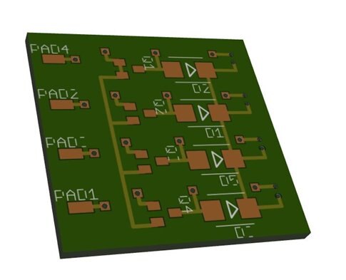
Ok so long story short, I fly RC aircraft one of them being micro size quadcopters, and I designed a circuit for one of them. It looks good but when I try to export as a gerber using the CAM thing it makes the gerber files way too big... the size of the whole circuit is only about 25mm x 25mm or so but it makes the file huge (I use an online gerber viewer) webGerber
I have tried several "jobs" to no avail... getting very annoyed. It makes the circuit correctly, but it makes the board way way too big. I attached the brd file... if you can't help me do it myself, can someone at least do the gerber conversion for me?