element14 Community
element14 Community
    Register Log In
  • Site
  • Search
  • Log In Register
  • Community Hub
    Community Hub
    • What's New on element14
    • Feedback and Support
    • Benefits of Membership
    • Personal Blogs
    • Members Area
    • Achievement Levels
  • Learn
    Learn
    • Ask an Expert
    • eBooks
    • element14 presents
    • Learning Center
    • Tech Spotlight
    • STEM Academy
    • Webinars, Training and Events
    • Learning Groups
  • Technologies
    Technologies
    • 3D Printing
    • FPGA
    • Industrial Automation
    • Internet of Things
    • Power & Energy
    • Sensors
    • Technology Groups
  • Challenges & Projects
    Challenges & Projects
    • Design Challenges
    • element14 presents Projects
    • Project14
    • Arduino Projects
    • Raspberry Pi Projects
    • Project Groups
  • Products & Partners
    Products & Partners
    • Arduino
    • Avnet & Tria Boards Community
    • Dev Tools
    • Manufacturers
    • Multicomp Pro
    • Product Groups
    • Raspberry Pi
    • RoadTests & Reviews
  • About Us
    About the element14 Community
  • Store
    Store
    • Visit Your Store
    • Choose another store...
      • Europe
      •  Austria (German)
      •  Belgium (Dutch, French)
      •  Bulgaria (Bulgarian)
      •  Czech Republic (Czech)
      •  Denmark (Danish)
      •  Estonia (Estonian)
      •  Finland (Finnish)
      •  France (French)
      •  Germany (German)
      •  Hungary (Hungarian)
      •  Ireland
      •  Israel
      •  Italy (Italian)
      •  Latvia (Latvian)
      •  
      •  Lithuania (Lithuanian)
      •  Netherlands (Dutch)
      •  Norway (Norwegian)
      •  Poland (Polish)
      •  Portugal (Portuguese)
      •  Romania (Romanian)
      •  Russia (Russian)
      •  Slovakia (Slovak)
      •  Slovenia (Slovenian)
      •  Spain (Spanish)
      •  Sweden (Swedish)
      •  Switzerland(German, French)
      •  Turkey (Turkish)
      •  United Kingdom
      • Asia Pacific
      •  Australia
      •  China
      •  Hong Kong
      •  India
      •  Japan
      •  Korea (Korean)
      •  Malaysia
      •  New Zealand
      •  Philippines
      •  Singapore
      •  Taiwan
      •  Thailand (Thai)
      •  Vietnam
      • Americas
      •  Brazil (Portuguese)
      •  Canada
      •  Mexico (Spanish)
      •  United States
      Can't find the country/region you're looking for? Visit our export site or find a local distributor.
  • Translate
  • Profile
  • Settings
Autodesk EAGLE
  • Products & Partners
  • More
Autodesk EAGLE
Forum Hi Rechard, I need your help on these questions please!
  • Blog
  • Forum
  • Documents
  • Events
  • Polls
  • Files
  • Members
  • Mentions
  • Sub-Groups
  • Tags
  • More
  • Cancel
  • New
Join Autodesk EAGLE to participate - click to join for free!
Actions
  • Share
  • More
  • Cancel
Forum Thread Details
  • Replies 2 replies
  • Subscribers 188 subscribers
  • Views 541 views
  • Users 0 members are here
  • eagle
  • settings
  • cadsoft
Related

Hi Rechard, I need your help on these questions please!

Michael
Michael over 15 years ago

Hi Rechard, I encountered several issues when using EAGLE, could you please help me out these? Please see the questions listed below. Thank you!


1. What purpose the netclass is used for? Is netclass only effective for Autorouter?
I leaned from the Manual that the netclass settings could be used when Autorouter is running; I guess it may be used under other circumstances too, but I am not sure about it, could you please make it clear for me? Thank you!
 
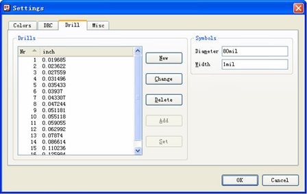
2. The image shown below is the Drill tag of Setting window that popped up when running SET command. Please help to explain the function of “Add” and “Set” buttons in the window, and when do they become usable? And what is the “Drills” list used for?
image
 
3. As per the explanation in the Manual, a device with four gates named respectively A, B, C and D would be placed in schematic in the order that their names indicate, which means gate A the first and D the last. But I’m wondering what if those gates are named with the characters that have no regularity, for example four gates with the names such as 2A, B5, XY, and ST3. What will happen when these gates are placed in a schematic?
 
 
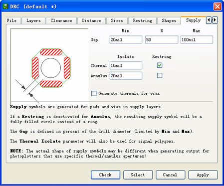
4. The figure shown below is the Shapes tag of DRC window; I am not clear about the Restring check-box after the Thermal and Annulus text-box, what’s the different if they are checked?
image
 
5. The Section 6.8 Combining Small Circuit Board on a Common Panel described the procedure of combination, and the 8th step said that we can export design rules as a dru file and import to the combined larger board to make sure the new board has the same DRC set as original ones. But I am wondering if there are two original boards featured with two different design rule settings, which setting would be imported to the newly combined board?
  • Sign in to reply
  • Cancel
  • Michael
    Michael over 15 years ago in reply to Richard_H

    Thank you very much, it's really helpful!!!

    • Cancel
    • Vote Up 0 Vote Down
    • Sign in to reply
    • Cancel
  • Richard_H
    Richard_H over 15 years ago

    Hi Michael,

    1. What purpose the netclass is used for? Is netclass only effective for Autorouter?
    I leaned from the Manual that the netclass settings could be used when Autorouter is running; I guess it may be used under other circumstances too, but I am not sure about it, could you please make it clear for me? Thank you!

    Basically you assign a certain minimum width and clearance value to certain signals. You are right: the autorouter takes care on these values, as the Follow me router does. It is affects also manual routing in case you have the option Automatically set width and drill for manual routing in the menu Options/Set/Misc active. Clicking onto a signal in the layout will automatically set the min. wire width given in the net classes. And finally the Design Rule Check will take these values for checking all the traces in the layout.


    2. The image shown below is the Drill tag of Setting window that popped up when running SET command. Please help to explain the function of “Add” and “Set” buttons in the window, and when do they become usable? And what is the “Drills” list used for?
    image
     

    This list assigns drill symbols with a certain drill diameter. In the manual you find a table of drill symbols. Symbol No. 1 looks like a plus sign, for example. Here you define your own table that fits to the drill diameters in the board. If you use the Set option, EAGLE list all used drills (maximum 18 different values) and assigns them to the drill symbols automatically. The drill symbols are drawn in the layers 44 and 45. You can see them

    when displaying these layers. The purpose is for printing a drill plan which can help in drilling boards manually.
    By the way: It has nothing to do with the drill table EAGLE creates when generating drilling data with the CAM Processor.


    3. As per the explanation in the Manual, a device with four gates named respectively A, B, C and D would be placed in schematic in the order that their names indicate, which means gate A the first and D the last. But I’m wondering what if those gates are named with the characters that have no regularity, for example four gates with the names such as 2A, B5, XY, and ST3. What will happen when these gates are placed in a schematic?

    The order of the gates depends on the order you placed them in the device. It has nothing to do with the gate names. The first gate you get with ADD in the schematic is the same you placed first in the device editor and so on.


    4. The figure shown below is the Shapes tag of DRC window; I am not clear about the Restring check-box after the Thermal and Annulus text-box, what’s the different if they are checked?
    image

    The restring setting for an annulus symbol changes the appearance of the symbol. If restring is active, there is an isolation ring around the drilling. If you set it off, the isolation symbol will be a filled circle. the whole area around the drilling is copper free. Restring for Thermals behaves similar. If you deactivate Restring there, the isolation area will be created directly at the border of the drilling. This will result in a smaller diameter of the thermal symbols in supply layers.


    5. The Section 6.8 Combining Small Circuit Board on a Common Panel described the procedure of combination, and the 8th step said that we can export design rules as a dru file and import to the combined larger board to make sure the new board has the same DRC set as original ones. But I am wondering if there are two original boards featured with two different design rule settings, which setting would be imported to the newly combined board?


    You decide about the Design Rules. If you want to combine two boards with different sets of Design Rules you have to find a compromise. If this is not possible you shouldn't combine them. image


    Hope this helps.


    Best regards,

    Richard

    • Cancel
    • Vote Up 0 Vote Down
    • Sign in to reply
    • Cancel
element14 Community

element14 is the first online community specifically for engineers. Connect with your peers and get expert answers to your questions.

  • Members
  • Learn
  • Technologies
  • Challenges & Projects
  • Products
  • Store
  • About Us
  • Feedback & Support
  • FAQs
  • Terms of Use
  • Privacy Policy
  • Legal and Copyright Notices
  • Sitemap
  • Cookies

An Avnet Company © 2026 Premier Farnell Limited. All Rights Reserved.

Premier Farnell Ltd, registered in England and Wales (no 00876412), registered office: Farnell House, Forge Lane, Leeds LS12 2NE.

Follow element14

  • X
  • Facebook
  • linkedin
  • YouTube