Hi Rechard, I encountered several issues when using EAGLE, could you please help me out these? Please see the questions listed below. Thank you!
Hi Michael,
1. What purpose the netclass is used for? Is netclass only effective for Autorouter?I leaned from the Manual that the netclass settings could be used when Autorouter is running; I guess it may be used under other circumstances too, but I am not sure about it, could you please make it clear for me? Thank you!
Basically you assign a certain minimum width and clearance value to certain signals. You are right: the autorouter takes care on these values, as the Follow me router does. It is affects also manual routing in case you have the option Automatically set width and drill for manual routing in the menu Options/Set/Misc active. Clicking onto a signal in the layout will automatically set the min. wire width given in the net classes. And finally the Design Rule Check will take these values for checking all the traces in the layout.
2. The image shown below is the Drill tag of Setting window that popped up when running SET command. Please help to explain the function of “Add” and “Set” buttons in the window, and when do they become usable? And what is the “Drills” list used for?
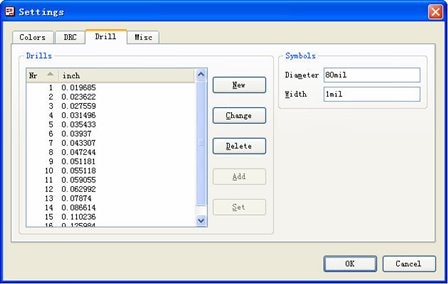
This list assigns drill symbols with a certain drill diameter. In the manual you find a table of drill symbols. Symbol No. 1 looks like a plus sign, for example. Here you define your own table that fits to the drill diameters in the board. If you use the Set option, EAGLE list all used drills (maximum 18 different values) and assigns them to the drill symbols automatically. The drill symbols are drawn in the layers 44 and 45. You can see them
when displaying these layers. The purpose is for printing a drill plan which can help in drilling boards manually.
By the way: It has nothing to do with the drill table EAGLE creates when generating drilling data with the CAM Processor.
3. As per the explanation in the Manual, a device with four gates named respectively A, B, C and D would be placed in schematic in the order that their names indicate, which means gate A the first and D the last. But I’m wondering what if those gates are named with the characters that have no regularity, for example four gates with the names such as 2A, B5, XY, and ST3. What will happen when these gates are placed in a schematic?
The order of the gates depends on the order you placed them in the device. It has nothing to do with the gate names. The first gate you get with ADD in the schematic is the same you placed first in the device editor and so on.
4. The figure shown below is the Shapes tag of DRC window; I am not clear about the Restring check-box after the Thermal and Annulus text-box, what’s the different if they are checked?
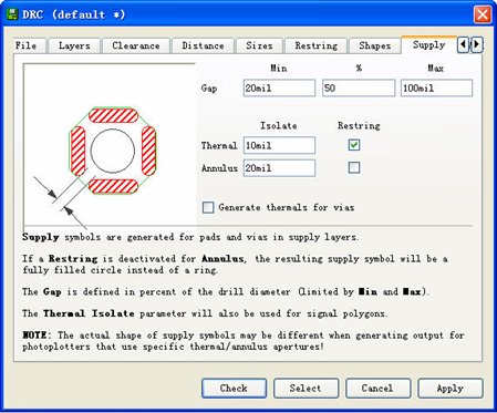
The restring setting for an annulus symbol changes the appearance of the symbol. If restring is active, there is an isolation ring around the drilling. If you set it off, the isolation symbol will be a filled circle. the whole area around the drilling is copper free. Restring for Thermals behaves similar. If you deactivate Restring there, the isolation area will be created directly at the border of the drilling. This will result in a smaller diameter of the thermal symbols in supply layers.
5. The Section 6.8 Combining Small Circuit Board on a Common Panel described the procedure of combination, and the 8th step said that we can export design rules as a dru file and import to the combined larger board to make sure the new board has the same DRC set as original ones. But I am wondering if there are two original boards featured with two different design rule settings, which setting would be imported to the newly combined board?
You decide about the Design Rules. If you want to combine two boards with different sets of Design Rules you have to find a compromise. If this is not possible you shouldn't combine them.
Hope this helps.
Best regards,
Richard
Hi Michael,
1. What purpose the netclass is used for? Is netclass only effective for Autorouter?I leaned from the Manual that the netclass settings could be used when Autorouter is running; I guess it may be used under other circumstances too, but I am not sure about it, could you please make it clear for me? Thank you!
Basically you assign a certain minimum width and clearance value to certain signals. You are right: the autorouter takes care on these values, as the Follow me router does. It is affects also manual routing in case you have the option Automatically set width and drill for manual routing in the menu Options/Set/Misc active. Clicking onto a signal in the layout will automatically set the min. wire width given in the net classes. And finally the Design Rule Check will take these values for checking all the traces in the layout.
2. The image shown below is the Drill tag of Setting window that popped up when running SET command. Please help to explain the function of “Add” and “Set” buttons in the window, and when do they become usable? And what is the “Drills” list used for?
This list assigns drill symbols with a certain drill diameter. In the manual you find a table of drill symbols. Symbol No. 1 looks like a plus sign, for example. Here you define your own table that fits to the drill diameters in the board. If you use the Set option, EAGLE list all used drills (maximum 18 different values) and assigns them to the drill symbols automatically. The drill symbols are drawn in the layers 44 and 45. You can see them
when displaying these layers. The purpose is for printing a drill plan which can help in drilling boards manually.
By the way: It has nothing to do with the drill table EAGLE creates when generating drilling data with the CAM Processor.
3. As per the explanation in the Manual, a device with four gates named respectively A, B, C and D would be placed in schematic in the order that their names indicate, which means gate A the first and D the last. But I’m wondering what if those gates are named with the characters that have no regularity, for example four gates with the names such as 2A, B5, XY, and ST3. What will happen when these gates are placed in a schematic?
The order of the gates depends on the order you placed them in the device. It has nothing to do with the gate names. The first gate you get with ADD in the schematic is the same you placed first in the device editor and so on.
4. The figure shown below is the Shapes tag of DRC window; I am not clear about the Restring check-box after the Thermal and Annulus text-box, what’s the different if they are checked?
The restring setting for an annulus symbol changes the appearance of the symbol. If restring is active, there is an isolation ring around the drilling. If you set it off, the isolation symbol will be a filled circle. the whole area around the drilling is copper free. Restring for Thermals behaves similar. If you deactivate Restring there, the isolation area will be created directly at the border of the drilling. This will result in a smaller diameter of the thermal symbols in supply layers.
5. The Section 6.8 Combining Small Circuit Board on a Common Panel described the procedure of combination, and the 8th step said that we can export design rules as a dru file and import to the combined larger board to make sure the new board has the same DRC set as original ones. But I am wondering if there are two original boards featured with two different design rule settings, which setting would be imported to the newly combined board?
You decide about the Design Rules. If you want to combine two boards with different sets of Design Rules you have to find a compromise. If this is not possible you shouldn't combine them.
Hope this helps.
Best regards,
Richard