element14 Community
element14 Community
    Register Log In
  • Site
  • Search
  • Log In Register
  • Community Hub
    Community Hub
    • What's New on element14
    • Feedback and Support
    • Benefits of Membership
    • Personal Blogs
    • Members Area
    • Achievement Levels
  • Learn
    Learn
    • Ask an Expert
    • eBooks
    • element14 presents
    • Learning Center
    • Tech Spotlight
    • STEM Academy
    • Webinars, Training and Events
    • Learning Groups
  • Technologies
    Technologies
    • 3D Printing
    • FPGA
    • Industrial Automation
    • Internet of Things
    • Power & Energy
    • Sensors
    • Technology Groups
  • Challenges & Projects
    Challenges & Projects
    • Design Challenges
    • element14 presents Projects
    • Project14
    • Arduino Projects
    • Raspberry Pi Projects
    • Project Groups
  • Products
    Products
    • Arduino
    • Avnet & Tria Boards Community
    • Dev Tools
    • Manufacturers
    • Multicomp Pro
    • Product Groups
    • Raspberry Pi
    • RoadTests & Reviews
  • About Us
    About the element14 Community
  • Store
    Store
    • Visit Your Store
    • Choose another store...
      • Europe
      •  Austria (German)
      •  Belgium (Dutch, French)
      •  Bulgaria (Bulgarian)
      •  Czech Republic (Czech)
      •  Denmark (Danish)
      •  Estonia (Estonian)
      •  Finland (Finnish)
      •  France (French)
      •  Germany (German)
      •  Hungary (Hungarian)
      •  Ireland
      •  Israel
      •  Italy (Italian)
      •  Latvia (Latvian)
      •  
      •  Lithuania (Lithuanian)
      •  Netherlands (Dutch)
      •  Norway (Norwegian)
      •  Poland (Polish)
      •  Portugal (Portuguese)
      •  Romania (Romanian)
      •  Russia (Russian)
      •  Slovakia (Slovak)
      •  Slovenia (Slovenian)
      •  Spain (Spanish)
      •  Sweden (Swedish)
      •  Switzerland(German, French)
      •  Turkey (Turkish)
      •  United Kingdom
      • Asia Pacific
      •  Australia
      •  China
      •  Hong Kong
      •  India
      •  Japan
      •  Korea (Korean)
      •  Malaysia
      •  New Zealand
      •  Philippines
      •  Singapore
      •  Taiwan
      •  Thailand (Thai)
      •  Vietnam
      • Americas
      •  Brazil (Portuguese)
      •  Canada
      •  Mexico (Spanish)
      •  United States
      Can't find the country/region you're looking for? Visit our export site or find a local distributor.
  • Translate
  • Profile
  • Settings
Autodesk EAGLE
  • Products
  • More
Autodesk EAGLE
Forum bench power supply
  • Blog
  • Forum
  • Documents
  • Events
  • Polls
  • Files
  • Members
  • Mentions
  • Sub-Groups
  • Tags
  • More
  • Cancel
  • New
Join Autodesk EAGLE to participate - click to join for free!
Actions
  • Share
  • More
  • Cancel
Forum Thread Details
  • State Verified Answer
  • Replies 42 replies
  • Answers 20 answers
  • Subscribers 191 subscribers
  • Views 9582 views
  • Users 0 members are here
Related

bench power supply

aster94
aster94 over 9 years ago

hello,


I started drawing in eagle this afternoon to make my first home made pbc board for a bench power supply that with an input of 12V/5A will have two output of 12V, 5V, 3.3V and an adjustable voltage (lm317)

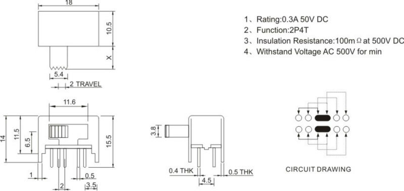
the switches are these with ground in the middle
565935243_150.jpg

I hope that the schematic is clear (it is also in the attachments), maybe you could give me some hint or advice about something that i m doing wrong

about the .brd i didn't route it since maybe you will say me to modify my schematic


thanks in advance


Immagine.png

Attachments:
bps.rar
  • Sign in to reply
  • Cancel
  • aster94
    0 aster94 over 9 years ago in reply to mcb1

    I m quite sure that i have somewhere a 19v 2a, stupid me that i didn t thought to use it before. And now that i am using more than 12v i will need to put the ams1117 after the lm7805 for sure


    I will move the voltmeter input as you said, thanks

    Do you have any suggestion about all these capacitators? Maybe just a 0.1uF ceramic in the input and one identical at both outputs will be ok

    • Cancel
    • Vote Up 0 Vote Down
    • Sign in to reply
    • Verify Answer
    • Cancel
  • mcb1
    0 mcb1 over 9 years ago in reply to aster94

    As COMPACT said the regulators need some voltage above their output.

    A good rule of thumb is 2v.


    Rather than go ot the 24v supply, many of the power bricks for laptops are 15v and have more than 2A capability.

    That assumes you want to have the adjustable voltage got from zero to 12v.


    Also a minor difference but if you can the voltmeter input should be on the Output of the ammeter.

    Most ammeters use a small resistance in series and measure the voltage across it to derive the current figure, some are negliglble but others are higher.


    You will need to be very disciplined when using the fixed output switch. You really don't want to have 5v (or worse) into a 3v3 device


    Otherwise it looks like it will work.


    Mark

    • Cancel
    • Vote Up 0 Vote Down
    • Sign in to reply
    • Verify Answer
    • Reject Answer
    • Cancel
  • aster94
    0 aster94 over 9 years ago in reply to COMPACT

    thanks, i know that i wouldn't be able to output more than Vin-1.15V, i will put the protection diode as you suggested. yes, your assumption is correct, it will be feeded with 12V already regulated

    the heatsink will not be a problem the case will be a panel of alluminium


    anyway i edited my previous message before seeing that you had commented

    • Cancel
    • Vote Up +1 Vote Down
    • Sign in to reply
    • Verify Answer
    • Cancel
  • COMPACT
    0 COMPACT over 9 years ago

    I'd definitely put polarity protection at the input.

    Your original design also makes the assumption that you are feeding the board with 12VDC regulated. Is this the case?

    With a linear regulator you can't output 12V from an input of 12V.

    A linear regulator works on the premise that excess power is dissipated as heat but can't absorb heat to boost voltage.


    I suggest that you start with a prototype first and test it out to see if it meets your needs.

    1. with input protection.

    2. with a single output.


    Once this is working then add your bells and whistles.

    And once this has been done then layout your PCB with sufficiently sized copper traces.


    Make sure that the regulators are sufficiently heatsunk to dissipate the unwanted power keeping the regulator temperature within operating bounds.

    • Cancel
    • Vote Up 0 Vote Down
    • Sign in to reply
    • Verify Answer
    • Reject Answer
    • Cancel
  • aster94
    0 aster94 over 9 years ago

    finally I'm back! looking a little bit around i found that the lm317 is not the best IC to use in parallel: LM317 in parallel - Answered -> LM2596 circuit question  so i will just be happy with its <1.5A


    i draw again the circuit with your precious suggestions:


    image


    now i have the input of 12V filtered by a 1000uF electrolityc and a 0.1uF ceramic capacitators with:

    -"high" current output with the lm317 (i think that now it is correctly wired)

    -low current output where i could choose between 12/5/3.3 volts


    the ammeter/voltmater that i am using is this: https://it.aliexpress.com/item/1pcs-DC-100V-10A-Voltmeter-Ammeter-Blue-Red-LED-Amp-Dual-Digital-Volt-Meter-Gauge-Voltage… as i said before it's the same that jw0752 is using


    i think that i could start to draw the board, anyone have any suggestion?


    about the power supply from the 220V I was undecided between: https://it.aliexpress.com/item/Free-shipping-2pcs-lot-Power-adapter-EU-UK-AU-US-AC110-220V-to-DC12V-2A-led/1806497704.ht…  and https://it.aliexpress.com/item/New-24W-Regulated-Switching-Power-Supply-LED-Driver-Lighting-Transformer-For-LED-Strip-Li…

    the second one is far away better, isn't it?


    EDIT: i was thinking that maybe the ams1117 would stay in a safer position if i use the Vout from the lm7805, correct?

    EDIT2: instead of all these output caps (3,4,5,6,7,8) wouldn't be better if a just put a 100nF ceramic cap before every output? or do you think i will need more filtering?

    • Cancel
    • Vote Up +1 Vote Down
    • Sign in to reply
    • Verify Answer
    • Cancel
  • mcb1
    0 mcb1 over 9 years ago in reply to aster94

    Glad we can help.


    The datasheet gives some explanation and an example of increasing the current.

    www.ti.com/lit/ds/symlink/lm317.pdf

    https://www.google.co.nz/


    "My home built supply has a 'LOAD' switch added between the output and the terminals"

    Could you explain this? I m sorry i didn t


    I have a switch that interrupts the voltage going to the output terminal.

    • Cancel
    • Vote Up +1 Vote Down
    • Sign in to reply
    • Verify Answer
    • Reject Answer
    • Cancel
  • aster94
    0 aster94 over 9 years ago in reply to mcb1

    Thanks Mark for your helpful comment,  the works that you posted look great and not complicated even for my level! For sure my next power supply will be based on the xl4016 board of your link


    I m also very happy to discoved that jw0752 and I are using the same voltage/ammeter


    I was thinking: could i wire two 317 in parallel to have around 3A? Really i don t need them but who knows in the future image

    I already thought to a solution to have an hight current output and a low current output through the switch (so max 0.5A)


    "My home built supply has a 'LOAD' switch added between the output and the terminals"

    Could you explain this? I m sorry i didn t understood


    In the next days i will draw everything again using the suggestion of everyone

    • Cancel
    • Vote Up +1 Vote Down
    • Sign in to reply
    • Verify Answer
    • Cancel
  • mcb1
    0 mcb1 over 9 years ago in reply to aster94

    Good questions.

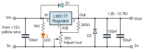
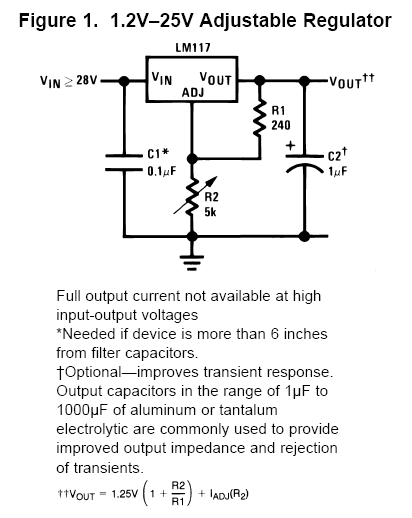
    Often the potentiometer/adjustable resistor is shown as above, when the correct drawing should be as per your link. (shown below)


    image


    Diode D1 is there to protect the regulator from a voltage on the output flowing back through the regulator when the input voltage is removed.

    D2 would offer protection if a reverse voltage source was connected at the output.


    My home built supply has a 'LOAD' switch added between the output and the terminals, to allow the voltage to be removed instantly, or set before powering up the connected device.


    The only issue you'll find is that you are limited to 1.5 A from the regulator.


    I'd have a look at jw0752 interesting foray into power supplies.


    Comparing Power Supplies

    (Links to both articles)


    Mark

    • Cancel
    • Vote Up +2 Vote Down
    • Sign in to reply
    • Verify Answer
    • Reject Answer
    • Cancel
  • aster94
    0 aster94 over 9 years ago in reply to mcb1

    As it is clear I am an hobbyist, thanks for the hint about the current

    In your schematics the middle pin of the potentiometer is not connected,  is it correct?

    Is this schematic also good?

    http://www.electronics-tutorials.ws/articles/reg5.gif

    Are the two diode necessary?

    • Cancel
    • Vote Up +2 Vote Down
    • Sign in to reply
    • Verify Answer
    • Cancel
  • mcb1
    0 mcb1 over 9 years ago in reply to aster94

    the rated current it is 0.5 at 50v so I could reach 2A at 12v

    It doesn't work that way.


    The current specifies how much the switch will pass without damaging the contacts.

    The voltage specifies how high a voltage you can apply before you have problems with insulation, arcing over, etc.


    At 12v you still have 0.5A.


    The voltage/current can be different between AC and DC but it's usually not much.


    You could change your design.

    If you switched the ADJ pin with different values, you'll have the regulator doing all the work.

    image


    Mark

    • Cancel
    • Vote Up +2 Vote Down
    • Sign in to reply
    • Verify Answer
    • Reject Answer
    • Cancel
<>
element14 Community

element14 is the first online community specifically for engineers. Connect with your peers and get expert answers to your questions.

  • Members
  • Learn
  • Technologies
  • Challenges & Projects
  • Products
  • Store
  • About Us
  • Feedback & Support
  • FAQs
  • Terms of Use
  • Privacy Policy
  • Legal and Copyright Notices
  • Sitemap
  • Cookies

An Avnet Company © 2026 Premier Farnell Limited. All Rights Reserved.

Premier Farnell Ltd, registered in England and Wales (no 00876412), registered office: Farnell House, Forge Lane, Leeds LS12 2NE.

Follow element14

  • X
  • Facebook
  • linkedin
  • YouTube