
Welcome to the Hioki page on element14. Here you can find things such as our latest news, training videos, and product details. Additionally, you can engage with us in our forums.

Do you remember the "flux capacitor" that Doc Brown invented in "Back to the Future"? It was the core component in that iconic DeLorean which - after supplying it with 1.21 GW of energy - would allow Marty McFly to travel through time.
The "flux capacitor" in that classic movie of course is a work of fiction - but it definitely sounds sophisticated and actually pretty cool. The "zero-flux" in HIOKI's "zero-flux current sensors", on the other side, is neither a work of fiction nor a cool-sounding term invented by HIOKI's Japanese marketing team.
The term "flux" is widely used across various scientific and engineering fields, each with a specific definition tailored to its context. However, the core idea behind all these definitions is the concept of a flow through a surface or an amount of something passing through a specific area.
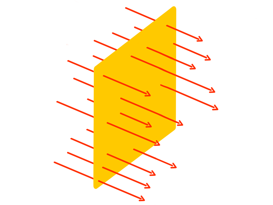
Since we are talking about current sensors, magnetic flux is the relevant type of flux. Magnetic flux refers to a measure of the quantity of magnetism, taking into account the strength and the extent of a magnetic field. Essentially, it represents the magnetic field's presence, strength, and orientation through a specified area.
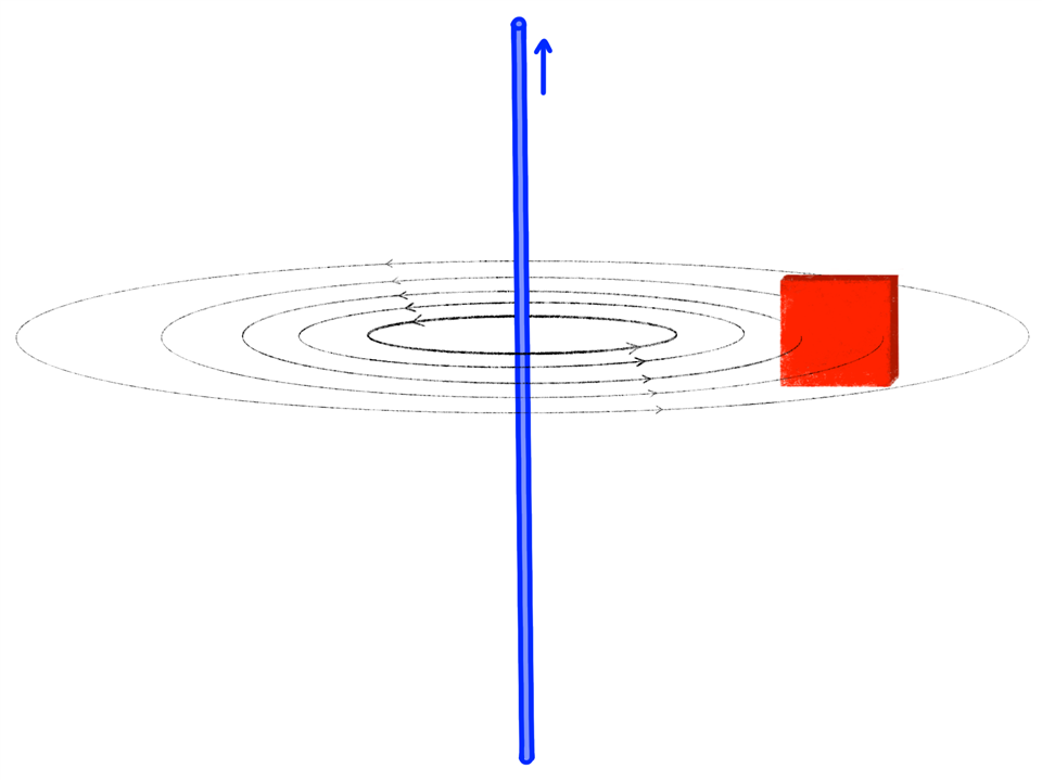
The reason why we look at this technology first is because flux plays a key role in this sensing method as well and it's a bit like a "prequel" of a zero flux current sensor.
Current sensors using this classic transducer principle for current detection are limited to AC. They are not the most accurate current sensors, but making them is not an overly complex procedure. A typical current sensor like this can be found in AC clamp meters that live in the tool bag of maintenance technicians for electrical installations.
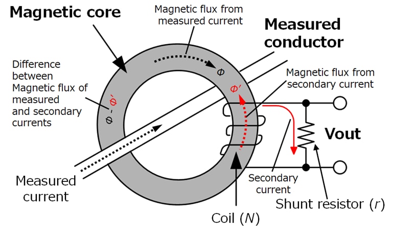
A classic AC current transducer works pretty closely to a transformer - only that the number of windings on the primary side is just one: The primary or measured current induces magnetic flux (Φ) into the magnetic core of the current sensor. This induces a secondary current into the coil (N), which flows through the shunt resistor (r). The flow of this secondary current induces magnetic flux into the magnetic core of the current sensor in the opposite direction (Φ'). Essentially, this is a negative feedback mechanism and the coil (N) is a feedback coil.
The magnetic flux generated by the measured and secondary currents ideally balance out each other completely. This ensures that the magnetic core does not become saturated. This is crucial to maintain the sensor's accuracy and overall functionality. If this balancing act worked perfectly, then this would already be a "zero flux current sensor" as the measured magnetic flux (Φ) and the opposing secondary magnetic flux (Φ') would be the same. Unfortunately, they are not the same for lower frequencies.
For high frequencies the secondary magnetic flux (Φ') balances out the magnetic flux of the measured current (Φ) very well. For lower frequencies or even DC the story is quite different - because like with transformers, these current transducers require AC to work. Therefore, an additional mechanism needs to be integrated to also balance out the magnetic flux for lower frequencies or DC.
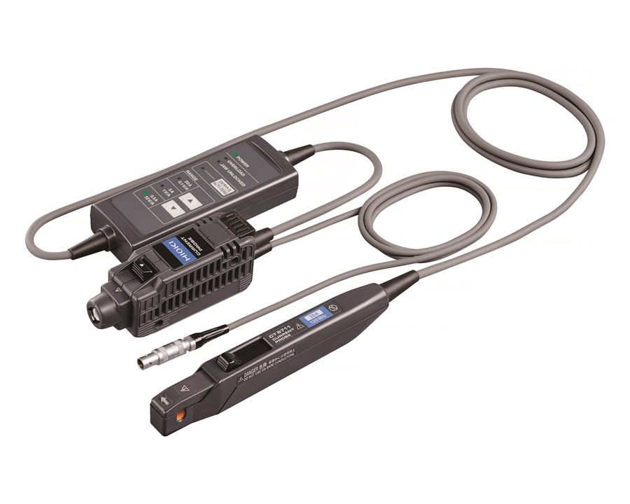
With this additional mechanism a current transducer can become a zero-flux current sensor. Basically, there are three different mechanisms that can be added to take care of the low frequency currents and DC:
Detection Coil (not for DC!)
Hall Element
Fluxgate
As it is the most simple mechanism and also the closest to the above current transducer principle, let's use the detection coil principle as example for a zero-flux current sensor. This principle is not suitable for DC currents, as it is based on another coil - but it allows for zero flux for AC currents from very low to very high frequencies.
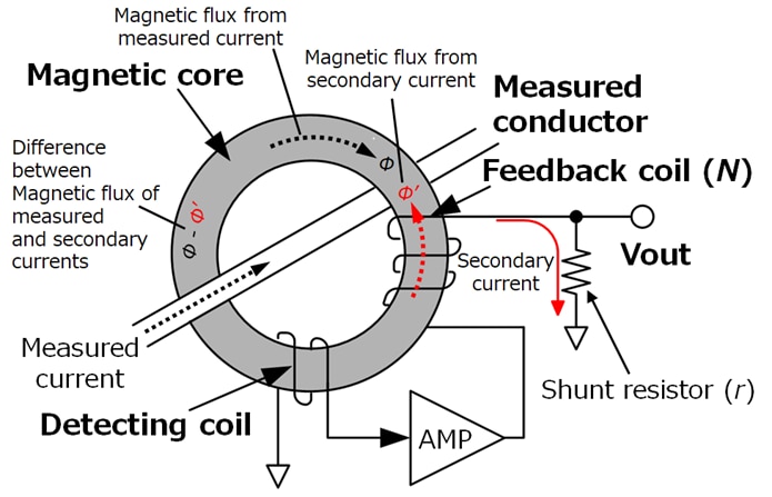
For higher frequencies, the current sensing principle of this zero-flux sensor is the same as the one used in a classic current transducer. In fact, regardless of which mechanism is used to handle low AC frequencies or DC, the current sensing principle for the higher frequency currents in a zero-flux sensor is always based on a feedback coil.
For low frequencies, the remaining magnetic flux (Φ-Φ’) induces current through the detecting coil. Based on this, an additional negative feedback current is added through an amplifier circuit into the feedback coil. This properly balances out the magnetic flux (Φ-Φ’) also in the low frequency regions and zero flux is achieved.
As a conclusion, despite the cool sounding and rather sophisticated name, a zero-flux current sensor has nothing to do with time travel. It has, however, the ability to accurately sense currents from DC or very low frequencies to high frequencies.
Did you know that HIOKI has been making current sensors since 1971? Here is a little tour through HIOKI's current sensing history.
Title image "1981 Delorean DMC-12 Time Machine" by Sicnag used under CC BY 2.0
The history of current sensors developed by HIOKI represents a journey of innovation and technical advancement in the field of electrical measurement. HIOKI, established in Japan in 1935, has been a pioneer in the electrical measurement industry, focusing on the development of professional and reliable testing and measuring instruments, including current sensors.
HIOKI's foray into the measurement field began with the production of electrical meters and testers, setting the stage for future developments in current sensing technology. The company's early commitment to quality and precision laid the groundwork for the advanced current sensors they would later develop.

The first current sensing device in the history of HIOKI was the CT-300 - an analog clamp meter introduced in 1971 which featured 5 current ranges, 3 voltage ranges and a resistance measurement function. This was followed in 1977 by the introduction of HIOKI's 3202 - the world's first clamp meter using LCD technology to display the measurement value.

The 3202 was a clamp meter capable to measure currents of up to 1000A. The closest modern-day equivalent would probably be HIOKI's CM4375-50 clamp meter which can also measure currents of up to 1000A. Just compare how the design of the jaws has been improved over the years, allowing today's clamp meter to be used in much tighter spaces.

One thing which was certainly not on the cards in 1977 was the support of Bluetooth functionalities which allow for the clamp meter to communicate with a smart phone or tablet and to transmit live measurement data. Today, HIOKI's Z3210 Bluetooth transceiver can be added to a an increasing range of measurement instruments, or it is already bundled with the instrument - for example as CM4375-90 .
But of course clamp meters are not the only HIOKI current sensing devices. In 1978 HIOKI released six different types of power meters to be used with clamp-on current sensors. One of them was the portable 3131 clamp-on power tester.

Today, the equivalent portable AC clamp power meter would be HIOKI's CM3286-50 . As you can see it has become a lot more compact, a lot more powerful as it also measures power consumption, it is battery powered and it also includes optional Bluetooth functionality.

Launched at the same time of HIOKI's portable 3131 was the 3133 clamp-on bench power tester.
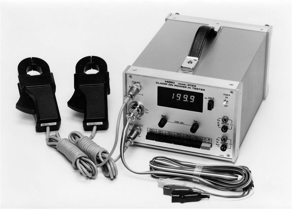
The 3133 power tester allowed to be connected to an optional power integrator called 3141, allowing to also measure power consumption. If the colors of the instruments remind you of the shirts worn by Sonny Crockett in Miami Vice in the mid 80s then HIOKI was way ahead of it's time in 1978.

HIOKI's clamp-on sensors of today are AC/DC zero-flux clamp-on sensors using fluxgate technology like the CT6844 for currents of up to 500A.

When used with a HIOKI power analyzer, these modern-day current sensors exchange additional information with the analyzer like output power ratio or the phase shift error of the sensor. But of course these sensors can also be used with any other power measurement or DAQ system. As with HIOKI's push-through current sensors like the CT6873 , which don't offer the same convenience of a clamp-on sensor but an even higher accuracy, they can be used with a sensor unit like HIOKI's CT9557 which provides a BNC output for the current measurement signal.
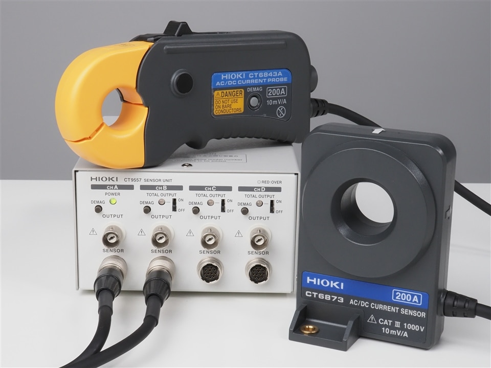
A sensor unit was also required with the 9273 AC current sensor that HIOKI introduced in 1993. It featured a bandwidth from 0.7Hz to 10MHz and a maximum input current of 20A.

The 9273 sensor already featured HIOKI's typical slide lock mechanism, and if you are familiar with today's HIOKI wideband current sensors then you can probably very quickly spot some design similarities.

At this time in the early 90s the sensor unit - or "current monitor" as it was called back then - did not offer a BNC output which would allow to directly connect the sensor to an oscilloscope. That changed in 1998 with the launch of HIOKI's 3273.

The 3273 current sensor was a wideband zero-flux current sensor using a hall element. The maximum input current was 15A (peak) and the bandwidth went from DC to 50MHz. The successor of this sensor is called 3273-50 and with it's improved maximum input current of 30A it is still available today.
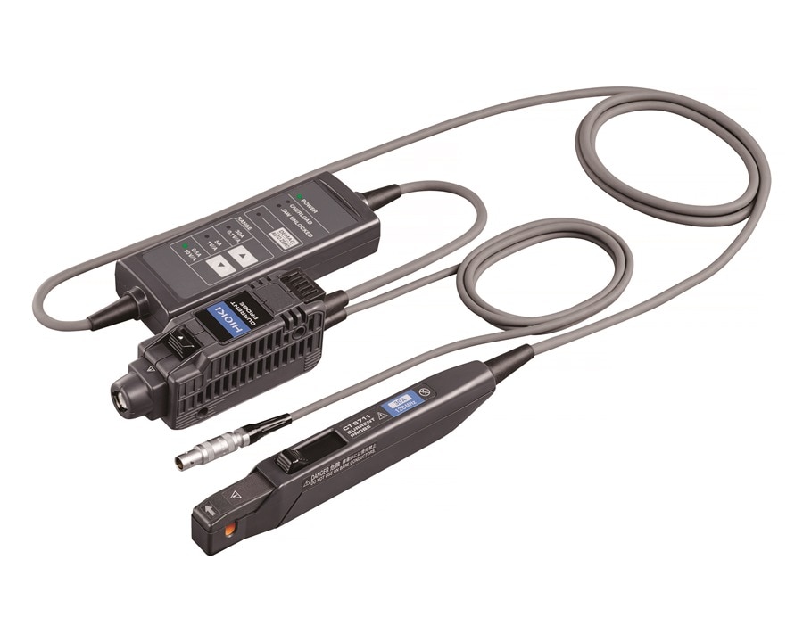
Of course, HIOKI didn't stop there and over the years introduced a wide variety of wideband current sensors to be used with oscilloscopes of all brands or HIOKI's own memory recorders - the latest one being the CT6711 with three current ranges from 0.5A to 30A and a bandwidth from DC to 120MHz.
Whether it's clamp meters, high-precision fluxgate sensors or wideband current probes: As the electrical world continues to evolve, the story of current sensing will surely continue for HIOKI.
All you needed was a precise sensor to measure DC current, and after talking to HIOKI you ended up ordering a 10MHz AC/DC current sensor... Does HIOKI employ sales magicians who can sell ice to eskimos? Or does bandwidth simply also matter when measuring DC?
When thinking of "bandwidth" in a measurement instrument the first thing that often comes to mind is the bandwidth definition of an oscilloscope. According to the standard for digitizing waveform recorders (IEEE 1057), electrical bandwidth is defined as the point at which the amplitude of a sine wave input is reduced by 3 dB (approximately 30%) relative to its level at a lower reference frequency.
Lets look at the frequency derating curve of HIOKI's CT6873 200A AC/DC current sensor with a bandwidth of 10MHz:
When a maximum DC input current of 400A has become a maximum input current of 0.7A at 10MHz then no degree in maths is required to quickly see that this is a reduction of more than 30%. That's because the derating of a current sensor and the sensor's bandwidth have nothing to do with each other.
But if bandwidth doesn't describe the current which the sensor can handle within that bandwidth - what does it describe?
Bandwidth is a measure of the range of frequencies a sensor can accurately respond to. For a current sensor, this would involve how quickly it can detect and respond to changes in the measured current. A common way to explain the relationship between response time and bandwidth (BW) is through the rise time (T_rise), which is the time required for a signal to go from 10% to 90% of its final value:
The following image illustrates the rise time of a current sensor:
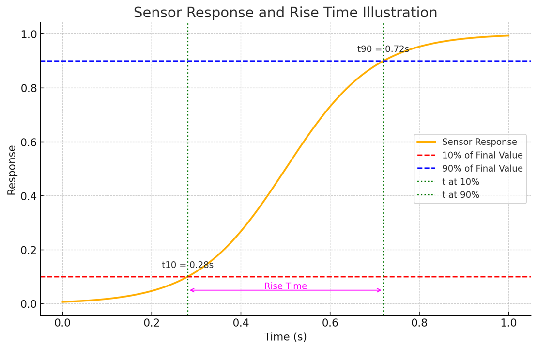
The orange curve represents how the sensor’s output responds over time to a step change in input. The horizontal dashed lines mark 10% and 90% of the sensor’s final output value. These levels are key points for measuring the rise time. The rise time is the period between when the output first reaches 10% of its final value and when it reaches 90%. It's indicated by the magenta double-ended arrow on the graph.
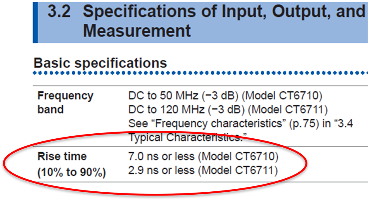
It’s important to note that the above formula does not apply to all current sensors – but in most situations the formula is correct. The following excerpt of HIOKI's CT6710 / CT6711 describes the rise time according to the above formula:
Even in applications focused on DC current measurement, a fast rise time of a current sensor allows to capture transient events. Such rapid changes in current levels might be due to startup/shutdown conditions, fault conditions, or switching events in the circuit. A current sensor with a sufficient bandwidth therefore allows to precisely capture for example the inrush / surge current of a motor start.
Also, DC current measurements can be affected by high-frequency noise or interference from various sources, such as electromagnetic interference (EMI) from nearby equipment, radio frequency interference (RFI), or switching noise from power electronics. A current sensor with sufficient bandwidth can more accurately represent the true current, including the detection and potential filtering of such noise components, which might otherwise distort the measurement or go undetected with a low-bandwidth sensor.
In summary, while the primary measurement interest might be DC currents, the bandwidth of a current sensor plays a crucial role in ensuring accurate, reliable, and comprehensive current measurements across a range of conditions and applications.
The evolution of battery technology in the last decades has allowed the development of many applications which simply wouldn't exist otherwise. Of course, one of the first things that comes to mind are electric cars. But what about battery powered vacuum cleaners (that are not just noisy but which actually clean)? Or new products like vapes, smart watches or e-bikes? They all require powerful yet lightweight batteries - and these batteries need to be developed, manufactured and tested. This is where Electrochemical Impedance Spectroscopy (EIS) can help.
EIS measures the impedance of a battery, which is its resistance to alternating current (AC) at different frequencies. Unlike direct current (DC) methods that only provide limited information, EIS captures a wide spectrum of internal reactions. By applying a small AC voltage and measuring the resulting current, EIS maps out the battery's impedance spectrum, revealing vital details about its internal chemistry and structure. One of the great advantages of using EIS for battery analysis is that it is completely non-destructive.
The data from EIS measurements are often represented in Nyquist plots (especially in Asia also known as Cole-Cole plot), which are graphs of the imaginary part of the impedance versus the real part. These plots can reveal a great deal about the internal processes and conditions of the battery, such as charge transfer resistance, mass transport limitations, and capacitive behavior.
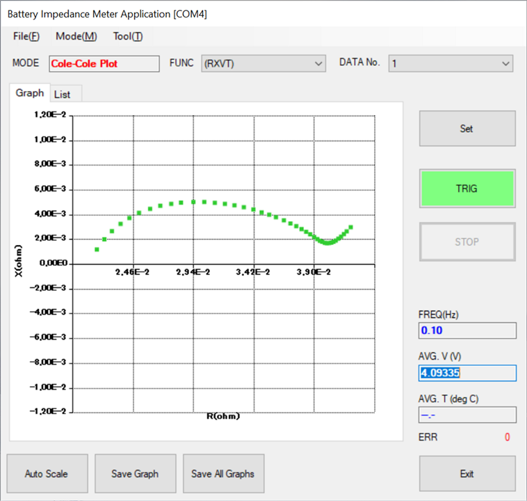
Let's take a more detailed look at what EIS allows us to analyze in batteries:
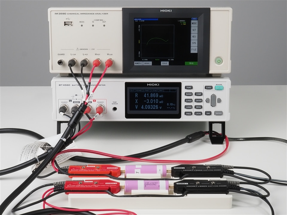
HIOKI has two instruments suitable for EIS in its portfolio. One is the IM3590 Chemical Impedance Analyzer and the second one is the BT4560 Battery Impedance Meter .
The IM3590 is perfectly suited for conducting EIS measurements in research and development of material science, chemistry, and electrochemistry. It's touch controlled and comes with a graphical interface that allows for Nyquist plots to be directly displayed on the screen. As it is typical for an impedance analyzer, frequency sweep points are set and stored directly in the instrument and no external control unit like a PC or PLC is required to make sweep measurements. That said, it is of course also possible to remote control the IM3590 - either through a PC and the included USB connector, or by adding an optional GPIB (Z3000 ), serial (Z3001 ) or LAN interface card (Z3002 ).
The frequency range of the IM3590 starts at 1mHz and goes up to 200kHz, making it suitable not only for the analysis of batteries but for a wide range of electrochemical studies and detailed impedance analysis across it's broad frequency range. Equivalent circuit analysis functions are natively included.

The BT4560 by itself is a battery impedance meter and it's perfect to test large capacity lithium ion cells thanks to it's "sweetspot frequency range" from 100mHz to 1050Hz and it's smallest resistance range of just 3mOhm. Being an impedance meter it doesn't natively support frequency sweeps, which is a requirement when performing EIS. That's why for EIS, the BT4560 needs to be controlled by a PLC or PC which sets the test frequencies and controls the sweep remotely. Equivalent circuit analysis can be performed with external tools like ZView.
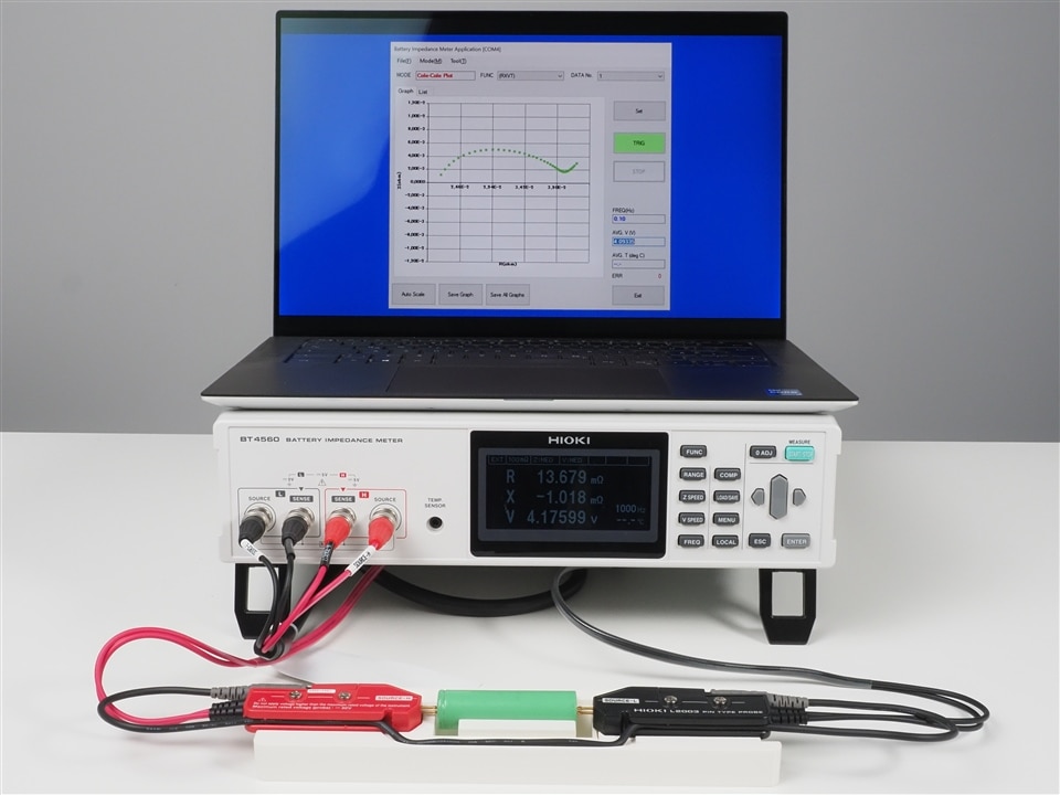
Comparing both instruments the IM3590 clearly looks like the superior instrument for EIS measurements. Then why would anyone consider the BT4560 as an alternative? Besides the price difference the smallest impedance range of the IM3590 is 100mOhm, which still makes it perfectly suited for measurements of the 18650 cells which are shown in the photos used to illustrate this text. However, if you intend to measure large capacity cells then the 3mOhm impedance range of the BT4560 offers a clear advantage. This is simply because the full scale error when measuring 1mOhm values in a 100mOhm range is likely to have a noticable effect.
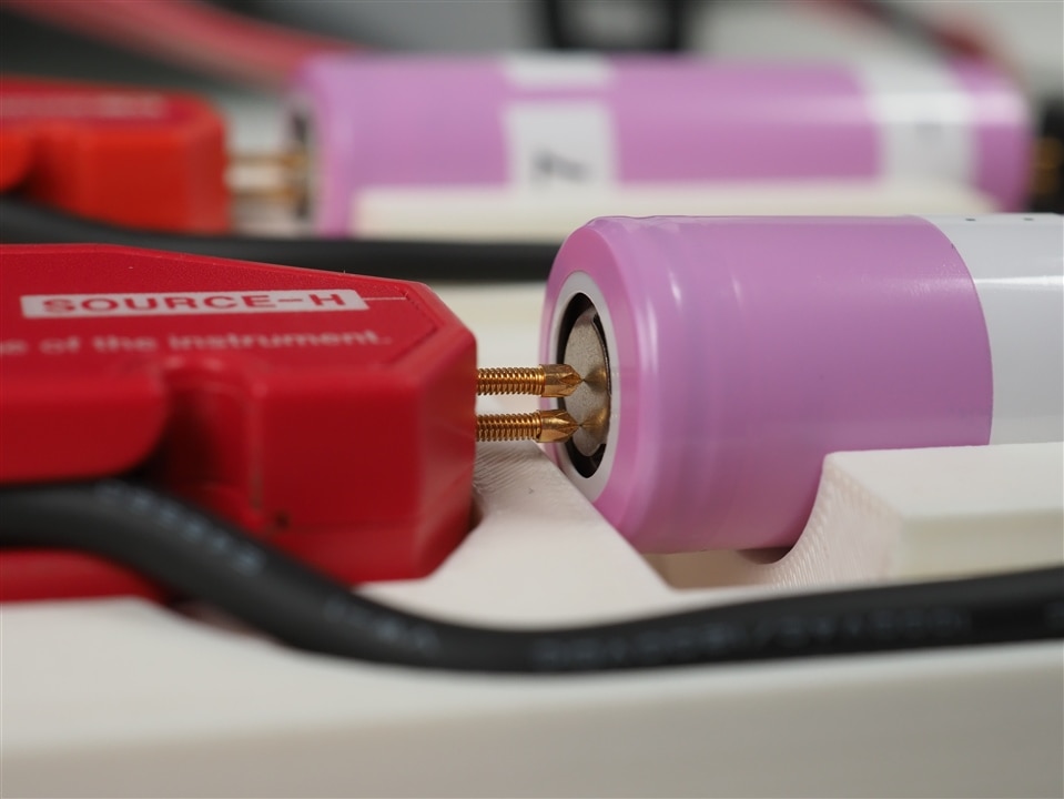
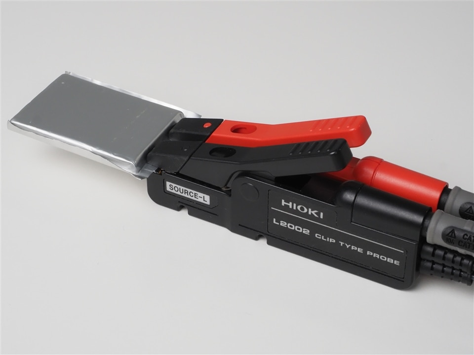
The measurement principle of both instruments is a 4-terminal-pair configuration which is designed to further reduces the influence of measurement cables compared to the more common 4-wire configuration. Suitable test probes from HIOKI are the L2002 clip type lead and L2003 pin type lead. While the L2002 cable is best suited to connect pouch type cells with a flat tab-style battery contacts or laminated sheet batteries, the L2003 is the right choice for cylindrical or prismatic cells.
You might have noticed in the above images that the BT4560 features are temperature sensor input. Recording the ambient temperature together with the impedance values does can be important in production environments as temperature does have an effect on the impedance value of a battery. The suitable temperature sensor for the BT4560 is called Z2005 .
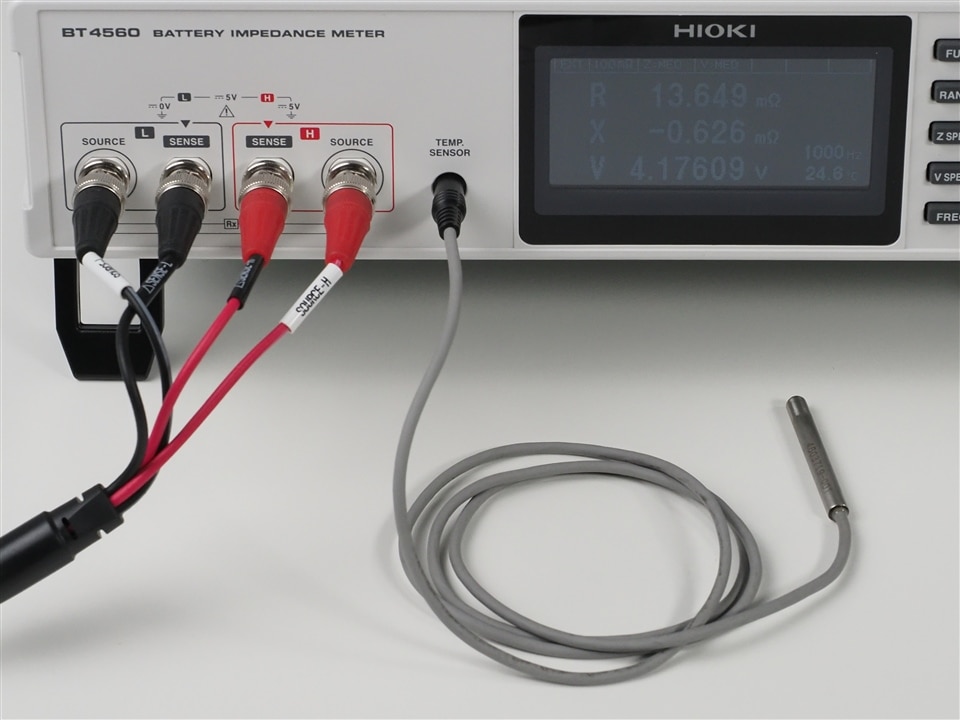
As a conclusion, EIS is a great tool to help you analyze batteries on cell level, and instruments like HIOKI's BT4560 or IM3590 allow you to perform EIS measurements quickly, easily and for all batteries, regardless of their type, size or capacity.
Some time ago HIOKI created a short video in which we briefly compared hall-sensor based current sensors with fluxgate based sensors:
In the video I said that "every hall sensor in the world has a DC drift" and therefore is not suitable for power measurements as this drift affects the accuracy of the measurement.
But what does "DC drift" mean? Does it mean that after 20 seconds into the measurement the measured value starts to drift away? Does it mean that after half an hour it has drifted away so much that the measured value is 20% higher than it should be?
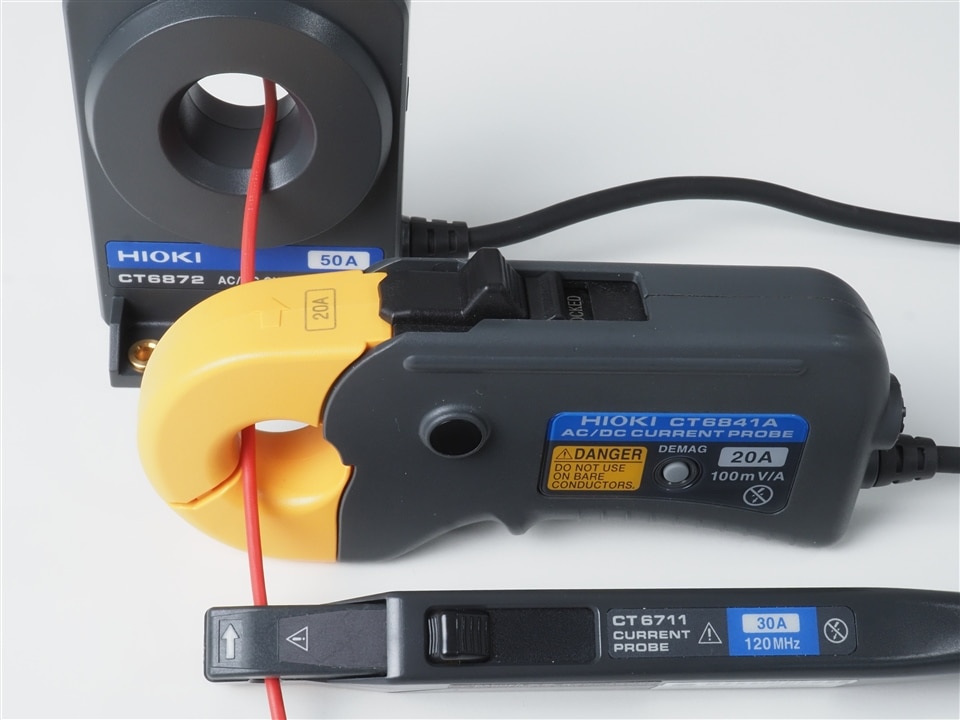
To show what DC drift in a hall-sensor based current probe means, I took a DC power supply, connected a 50 watts car light bulb with a supply voltage of 12V and picked a hall sensor based current probe as well as two fluxgate based current sensors for a comparison.
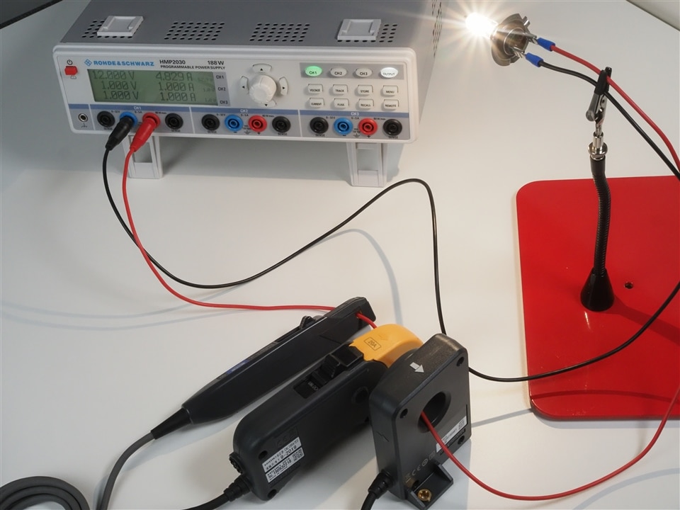
These were the current sensors chosen for this comparison:
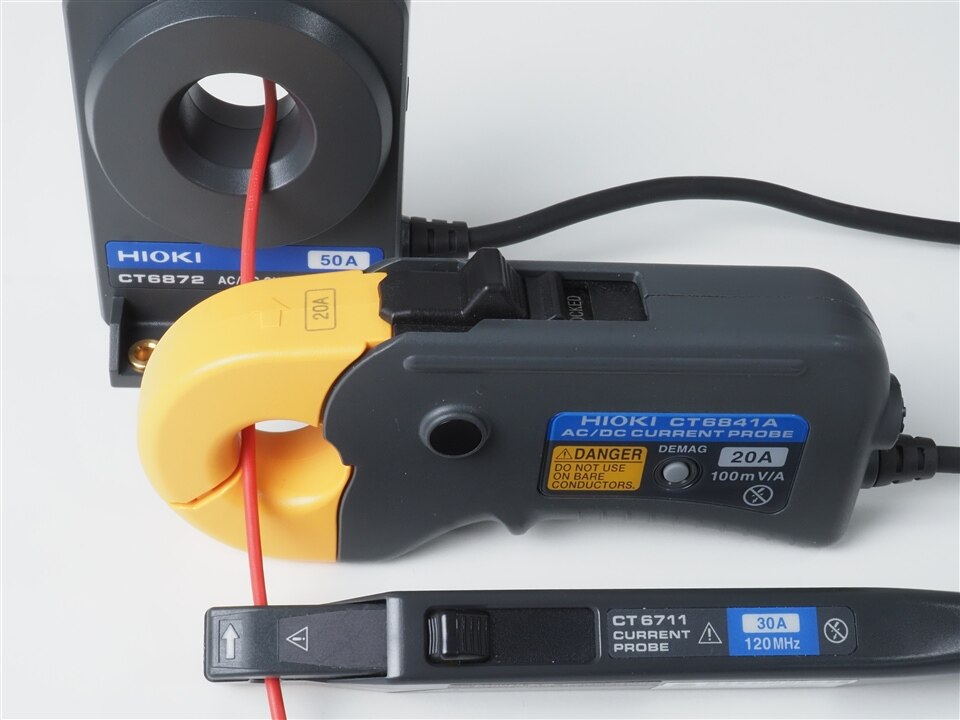
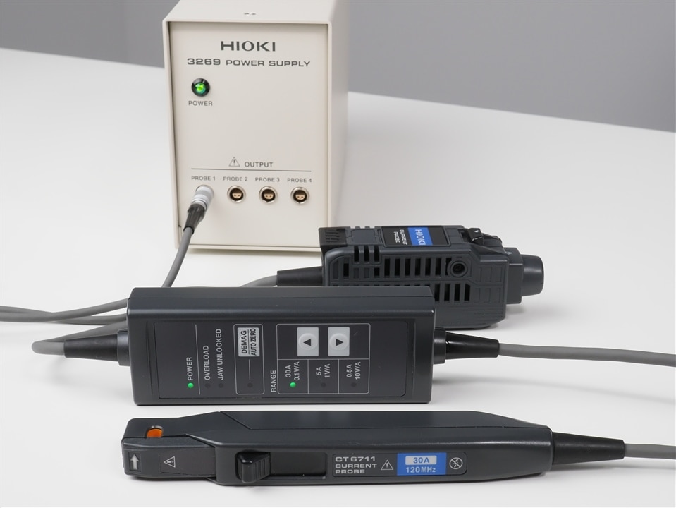
To record and compare the measured currents over a longer period of time, I connected them to a HIOKI MR6000 memory recorder. The CT6711 hall sensor based current probe has a BNC output as it is typically used with oscilloscopes or recorders. For this measurement I picked a high resolution unit for the MR6000 recorder called "8968" which offers a 16bit resolution. HIOKI's MR6000 memory recorder has a hardware option that provides the necessary power to drive the CT6711 or other current sensors with a 2-pin Lemo power supply connector. To use the CT6711 with an oscilloscope, a power supply unit is needed like HIOKI's 3269 or 3272 .
The two fluxgate based sensors CT6841A and CT6872 come with a proprietary ME15W connector. To connect them with an oscilloscope, a power supply unit CT9555 , CT9556 or CT9557 would be required which not only supplies the required power to drive the sensors but which also outputs the measured signal to a BNC connector.
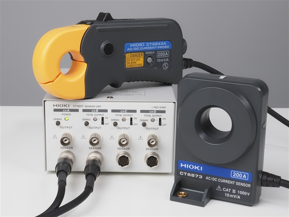
As I don't use an oscilloscope for this test but a HIOKI memory recorder, these current sensors can directly be connected to the recorder through a current sensor module called "U8977", which conveniently also offers a 16bit resolution.
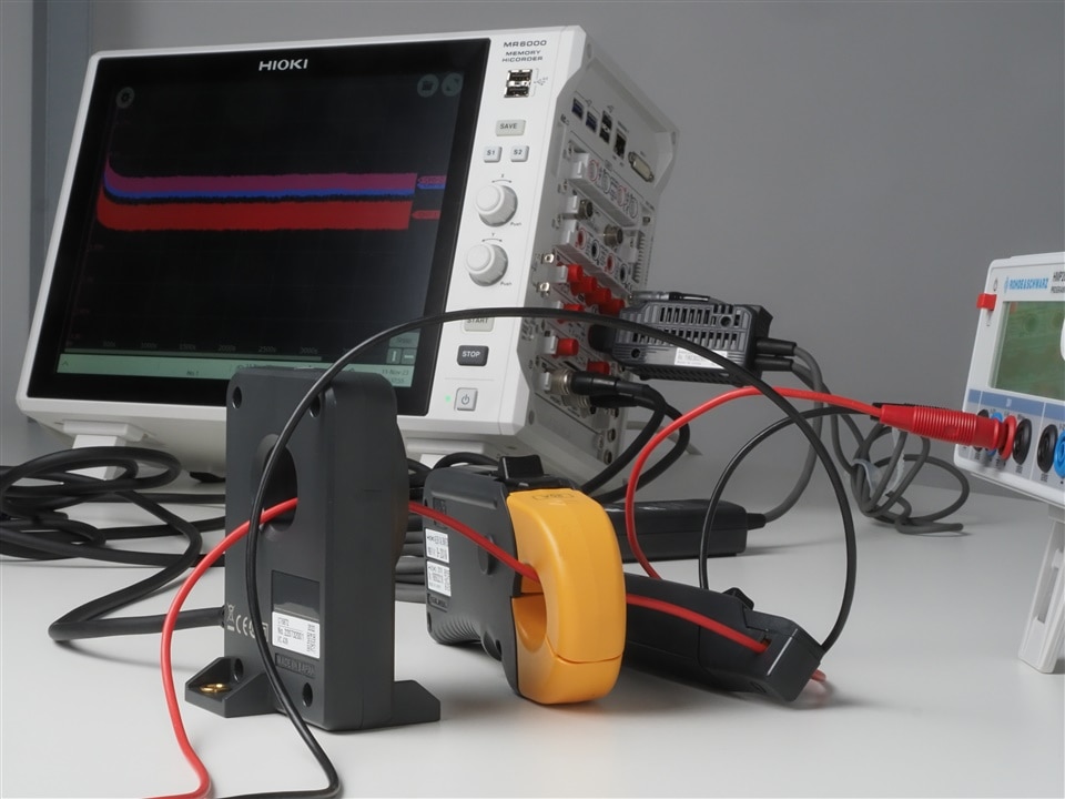
All that was needed now was to switch on the light bulb, record the current for an hour or so and show you how the CT6711 hall sensor based zero flux probe drifts away:
But as you can see there is no drift. Not at all. What you can see is that I have missed to zero-adjust the channels before starting the recording, which especially causes the CT6841A (red curve) to be displayed a little next to the other two measurement curves. While this was not intended, in this case it probably even helps to show that there are three curves on display. Because the CT6872 (blue curve) is hidden behind the curve of the CT6711 (green curve), here is the same recording with the CT6872 in front.
Both the CT6841A and the CT6872 are fluxgate based sensors, but the "thickness" of the curves is quite different. At this point we should remember that the CT6841A (red curve) is a current clamp while the CT6872 (blue curve) is a push-through sensor. Push-through sensors don't have the flexibility of a current clamp but their accuracy is superior. The difference becomes even more clear when you consider that the CT6841A has a 20A range while the CT6872 has a 50A range.
What we need to keep in mind here as well is that the load which is used for this experiment is a H7 car light bulb and not a precise programmable electronic load. This might have contributed to the "thickness" of the measurement curves, which in all recordings of this test have been made with only 100 samples per second (1MSa/s would have been possible). However, the "thickness" of the CT6841A curve, or the range between min and max values, is actually just around 30mA.
But again, more than one hour of recording with a hall sensor based zero flux probe, and there is no DC drift to be observed. The statement in the video was "not suitable for power measurement because those measurements take a long time". But isn't a measurement over one hour "a long time"?
Lets look at applications of power measurements where these sensors are typically used and which take a longer time: Especially the current clamps are very popular for WLTP measurements. Those measurements mean that the sensors get installed in cars. Not only cars, actually, but also engine rooms of cars. And what happens with sensors sitting in engine rooms when the engine is running? They heat up...
As you can see from the pictures above, the current sensors in the measurement were sitting on a desk. They were not sitting in an engine room of a car, a machine or close to an inverter where the temperature changes over time. So lets repeat the same measurement but this time simulate an environment with a changing temperature.
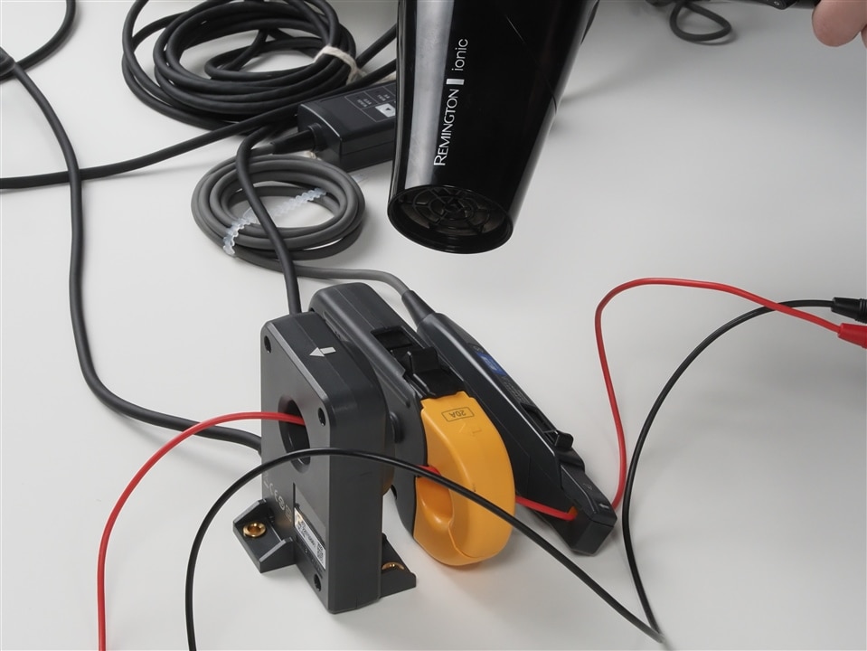
With no climate chamber quickly available, a hair dryer turned out to be a suitable and easily available alternative as heat source. Before restarting the test I have zero-adjusted the channels of the current input module, which is the reason why the curves of the CT684A and CT6872 are now on top of each other.
Once the hair dryer started to warm up the sensors, there is a clear drifting visible in the measurement curve of the CT6711. The curves of the fluxgate based sensors also suggest a small drift, but the current consumption of the light bulb actually did go up during that test - probably caused by the increasing temperature. So this slightly upwards moving curve of the CT6841A and CT6872 is not showing a sensor drift but the correct measurement.
As a conclusion, time itself does not cause a DC drift in a hall sensor based zero flux probe - temperature changes are required for that drift to happen over time. However, it doesn't mean that hall-sensor based current probes are perfect for power measurements as long as the temperature stays constant. Factors like face shift also play an important role in power measurement - especially at higher frequencies. If you want to know more about this then feel free to get in touch with us for a chat.
As so often it all began with a coincidence: In the mid-80s, the Japanese test & measurement equipment manufacturer HIOKI developed an AC milliohmmeter that allowed for an improved measurement of the contact resistance of switches and relays when compared with the previously used DC milliohmmeters. In the new device, HIOKI also galvanically isolated the device under test from the measuring circuit, which made the measurements independent of any electric potential between the two measurement points.
At about the same time, the Japanese researcher Akira Yoshino brought the lithium-cobalt dioxide accumulator, developed by John B. Goodenough, to market maturity. When measuring the resistance of these new accumulators, the AC measuring procedure turned out to be particularly suitable, because the various electric potentials between the two poles required a galvanic isolation between the device under test and the measuring circuit.
Thus, the “AC mΩ Hi Tester 3225”, which was originally developed for measuring the contact resistance, became the starting point of a success story for HIOKI in the field of lithium-ion batteries that has now lasted for more than 35 years. The original milliohmmeter has developed into an entire product family of battery testers for measuring battery cells, modules and packs.
In the production process of lithium-ion cells or batteries, the battery tester is not used until a fairly late stage. Resistance values, however, are verified much earlier in the process, because ensuring that resistance values are as low as possible and ideally always the same is critical for the quality of the battery. There are two main reasons for this.
On the one hand, a low overall resistance of a battery system is required to be firmly pushed back in your seat when kicking down the accelerator pedal in an electric sports car, for example. This is because the high-voltage battery pack needs to be able to feed a high current to the electric drive motor. Ohm's law explains quite simply how this relates to the resistance.
If we convert V = R I to I = V / R, we see that a small resistance R at the same voltage V means a large current flow I.
On the other hand, every resistance in a battery system causes electrical energy to be lost as thermal energy. This is not a phenomenon specific to batteries, but goes back to the generally applicable law of Joule heating – also known as “Joule's first law”.
The electrical power dissipated at the resistor can be described traditionally as P = V I. If you replace the voltage “V” by “RI” from Ohm's law mentioned above, you get P = V I = (R I) I. You can see how the power loss P increases as the resistance R increases.
When measuring the resistance, especially on batteries, a distinction is made between two measuring methods – the AC measurement and the DC measurement. In this case, the DC resistance measurement does not refer to the DC measurement of a battery’s internal resistance, where the internal resistance is determined via the voltage change when discharging the battery with a load. Here, DC measurement refers to measuring the resistance with a 4-wire measuring method and is used, for example, to measure the contact resistance. This method is applied in multimeters, (DC) resistance meters or insulation testers, for example. The AC measuring method, on the other hand, is used in battery testers or LCR meters.


If you go through the manufacturing process of a lithium-ion battery in chronological order, an important DC measurement of the electrical resistance takes place quite early after the electrodes have been coated with the active material. In this process, lit hium-alloyed material is applied to the electrode material under pressure and at appropriate temperatures.
Measuring the resistance after that allows for determining the specific electrical resistance of the applied active material and the contact resistance between the active material and the electrode. Until a few years ago, however, it was not easy to determine these two values separately, whereas measuring the contact resistance between the active material and the electrode material was a particular challenge. This changed with the market launch of a new electrode resistance measurement system – the RM2610 from HIOKI.

The RM2610 from HIOKI is basically a DC resistance meter. Instead of a traditional 4-wire measurement, however, the RM2610 works with a probe in which a total of 46 spring-loaded contacts are arranged on a total area of 1 mm2. During the measurement, a series of DC resistance measurements are performed between the contacts. Based on these measurement results, the resistivity of the active material and the contact resistance between the active material and the electrode are calculated with the help of a mathematical model and known parameters.
The known parameters are quantities that can be determined easily, such as the thickness of the electrode material, the layer thickness of the active material and the electrical conductivity of the electrode material. The anode is usually made of copper, while the cathode is usually made of aluminium. Copper cannot be used as a cathode material, because it would corrode at the cathode. Aluminium in turn, is unsuitable as an anode material because it reacts with lithium.
Even though the RM2610 is now often used as a tester in the production of lithium-ion cells, it was actually designed for use in development departments. The aim was to shorten the development process of cells with new materials by allowing developers to make a statement about the expected quality of the finished cell already after the coated electrodes have been manufactured. This was so unique and such an improvement of the process that HIOKI's electrode resistance measuring system was used by several dozens of customers in Asia while it was still in the prototype phase.
When determining the contact resistance of welding joints, the traditional 4-wire DC resistance measurement method is used. Regardless of whether these welding joints are intended to attach power terminals to a pouch cell or to connect a cell to a busbar – the contact resistance should always be checked afterwards to avoid introducing resistance-dependent heat sources at these points.
4-wire DC resistance measurements can be made with almost any digital multimeter for laboratory use or industrial use. However, when measuring the contact resistance in production, there are some important reasons to make the measurement with a resistance meter that is specially designed for this purpose.
The first important reason is the measuring range for the resistance. With a common and undoubtedly premium digital multimeter showing 7 ½ digits from one of the well-known manufacturers, the smallest resistance measuring range is 1 Ω. This sounds impressive at first, but the contact resistance of welded contacts for lithium-ion batteries should ideally be below 0.1 mΩ. HIOKI's RM3545 resistance meter easily meets this requirement with its smallest measuring range of just 10 mΩ at a resolution of 0.01 µΩ.

In addition to a very small measuring range, HIOKI's RM3545 has another function that is very useful in the production environment, which is checking the probe contact between the measuring device and the device under test during measurement: Here, the principle of 4-wire measurement is used to monitor that all 4 measuring contacts remain properly applied to the device under test during the measurement. This contact check function prevents measurements from being evaluated as “failed” due to incorrectly applied measuring contacts, and thus prevents flawless products from being sorted out erroneously.

Another very important reason for using a special resistance meter is the measuring speed: When the RM3545 is set to the fastest setting, the time between the start of measurement and the output of the measurement result is only 2.2 ms. This allows for conducting many contact measurements with only a few measuring devices and is therefore ideally suited for the numerous welding joints that need to be measured in a battery production line.

At this point, readers with production experience have any right to object that the mechanical transport of a device under test takes much longer than a few milliseconds, which clearly puts the advantage of a very high measuring speed into perspective in the overall context. To make effective use of the high measuring speed for production, HIOKI offers the RM3545-02 – a device variant with slots for multiplexer cards.

By adding two of the optionally available multiplexer cards , a single resistance meter is enabled to carry out up to 20 different 4-wire measurements one after the other in the shortest possible time when the devices under test are mechanically fed to the measuring device “in groups”. If this number of measuring channels is not sufficient, e.g. because all welded contacts of an entire battery module should be measured in one step, there is still no need to operate several RM3545 units side by side, whereas their parallel control would make the integration significantly more complex.

In this case, the use of a separate multiplexer system is recommended. HIOKI offers such a system in various versions, and in a configuration designed for 4-wire measurements it enables the control of up to 132 channels with a single measuring device such as the RM3545 (configuration: SW1002 + 12 × SW9001). The multiplexer unit is not limited to the use with resistance meters, but can also be used with HIOKI's battery testers, impedance meters or voltmeters – provided the measured voltages are below 60 V.
If you imagine a measurement setup with the above-mentioned 132 channels, which are used, for example, to measure the welded contacts for connections to busbars on a battery module, the 4-wire measurement method not only requires more than 500 test leads, but also more than 250 mechanical test contacts. From a technological perspective, this is possible. However, especially for cylindrical cells in a module, another solution is preferable – a flying probe tester with the somewhat cryptic name FA1240-W800. These devices are commonly used for testing assembled PCBs, and are capable of performing 4-wire resistance measurements, among other things, in as fast as 25 ms per test. After all, it does not matter whether the device under test is an assembled PCB or a battery module where welding joints are measured.

The use of a flying probe tester in the example of measuring welding joints of battery modules has another advantage over the arrangement with fixed test contacts – be it in the variant described above or alternatively with a “bed of nails”; because while the test positions are always the same on assembled PCBs, they always deviate slightly from each other on battery modules with hundreds of cells due to production tolerances. However, the welding joints must be measured precisely.
Therefore, the FA1240 flying probe tester allows for loading a position file for each battery module beforehand. This file can be created individually for each battery module with the right camera and a suitable analysis software. Measurement errors due to mechanical production tolerances are ruled out in this way.
A common question HIOKI is often asked is whether an existing battery tester can also be used for measuring contact resistances. There is one technical reason in favour of it, but there are also several more significant reasons against it.
One reason for using the AC measuring method provided by the battery tester for measuring contact resistances is that the electromotive force – also known as electromotance – plays no role in this measuring method. To put it simply, the electromotive force is a DC offset that occurs when different metals make contact. However, for an AC measurement the DC offset can be ignored.

This electromotive force is a very small voltage that has no measurable influence on the resistance measurement in the ohm range. The contact resistance, however, is definitely in the microohm range, and here even the smallest DC offset becomes relevant for the measurement result. At this point it is important to note that the above-mentioned DC resistance meter RM3545 has an offset voltage compensation function, which helps minimising the influence of the electromotive force.
One argument against the use of battery testers for measuring contact resistances is the eddy currents that can occur in the measuring leads during a 4-wire measurement, even at measuring frequencies of 1 kHz. As for the electromotive force, these eddy currents have no significance for larger resistances – but for the very low contact resistances they do have an influence on the measurement result. The difficulty here is that eddy currents can have different magnitudes for the same device under test, depending on how the measuring lead is routed. If, for example, the test lead is guided past a (magnetic) steel sheet such as a housing, this can produce a different measurement result than if the test leads are routed in a slightly different way with the same device under test. This is one reason why it can be difficult to obtain repeatable or precisely comparable measurement results when measuring the contact resistance with a battery tester.
Another reason arises when comparing the accuracies of the two measurement methods: One of the most widely used battery testers in the production environment is HIOKI's BT3562A . This battery tester’s basic accuracy for resistance measurement is 0.5 %. This is a very good value for an AC resistance meter. A DC resistance meter like the RM3545 , however, has a basic accuracy of 0.006 %.
Pair matching of cells
At the beginning of this text we said that not only small but also equal resistance values are decisive for the quality of a battery. Equal resistance values are particularly relevant for cells that are connected together in modules and packs.
When battery cells are connected in series, a single cell with a larger resistance would be a bottleneck for the entire system. The greater resistance would not only cause an increased temperature in the array, which would have a negative impact on the service life. This cell would also be discharged faster than the others. In common applications, a battery management system ensures that these deviations among cells are compensated for and are not noticeable to the regular user.
However, the situation is different if the battery is not only used for a regular electric vehicle, but for a championship racing car, for example. Or if an appropriately designed battery provides the entire power supply for an expedition vehicle. In both cases, it is beneficial to rule out any potential deviations between the individual cells being used.

This can be achieved by pair-matching the individual cells. The impedance of the individual cells is determined by electrochemical impedance spectroscopy at different frequencies. The impedance values, consisting of the ohmic resistance and the reactance, are combined to form a Nyquist plot for each cell. If these Nyquist plots are laid on top of each other, the cells whose Nyquist plots match the most can be combined to form a module or pack.
HIOKI's BT4560 battery impedance meter is also ideally suited for these measurements, because the formation of the eddy currents described above is minimised during the measurement by applying a 4-terminal-pair measurement.
To summarise, we can point out that the appropriate measurement technology is required especially for realising high-performance batteries. Each individual production step plays a critical role in the overall result of the battery.
For HIOKI, the close cooperation with leading battery manufacturers over decades is a guarantee for strengthening the battery market with both established and newly developed measurement technology.
Measuring DC resistances is one of the functions pretty much every bench multimeter provides. Then why would you need a separate resistance meter?
One of the best digital multimeters available on the market offers a lowest resistance range of 1 Ohm. That is great and more than sufficient when developing circuits or testing PCBs. However, when measuring the electrical resistance of conductive materials or welding contacts, then you are looking at values which are more in the mOhm or µOhm range. That's why the "smallest" bench resistance meter from HIOKI - the RM3544 - has a lowest resistance range of 30 mOhm. It's "bigger brother", the RM3545 , has a lowest resistance range of 10 mOhm and a resolution of just 0.01 µOhm.

Another aspect is measurement time: Multimeters are not necessarily optimized to perform measurements at high speed. HIOKI's resistance meters, on the other hand, have been designed to also perform resistance measurements in mass production environments where speed is an important factor. For example, when a module of lithium ion batteries is produced then typically the quality of every spot weld connection to the busbar is tested by measuring the contact resistance. The RM3545 can perform such a measurement in it's smallest 10 mOhm resistance range in just 41 ms (fast mode). In higher resistance ranges the measurement time is as low as 2.2 ms.
A very useful function - which is hard to find even in top of the range multimeters - is a contact check function: If activated, it only starts a measurement after ensuring that the probe has proper contact to the device under test. This is a feature surely not critical in a lab environment, but really useful in production environments where it helps to avoid rejects caused by poor contact of the probe to the DUT. N.B.: The contact check function is featured in the RM3545 , but neither in the RM3544 nor the RM3544-01 .

Coming back to the example with the busbar welds of the battery module: The longest time in a test process is mechanically moving the DUT to the test probe or test fixture. Once positioned, you want to perform as many tests as possible before having to mechanically move the DUT again. This is where multiplexers come into play. Especially when the number of tests to be performed is high, dedicated multiplexers like HIOKI's SW1002 provide the required number of measurement channels. If the number of channels required is 20 or less, then such a dedicated multiplexer unit isn't required. In this case the RM3545-02 offers two slots on the backside that can each hold a multiplexer card Z3003 . Each of these multiplexer cards offers 10 measurement channels for 4-wire measurements and they can easily be added to the RM3545-02 models. N.B.: You can only add multiplexer cards to the RM3545-02 model, but not to any other version of the RM3545 as those others don't have the slots required to add the cards.

4-wire measurements usually mean 4 connectors at the measurement instrument for the test lead. However, if you look closely at the RM3544 or RM3545 then you will see 5 connectors instead of 4. The 5th connector is the so called "guard terminal", which is designed to reduce measurement noise that can become relevant especially when test currents are small, i.e. in the high resistance ranges. Technically the guard terminal allows to "ground the shield" of the test lead. The guard terminal is supported in HIOKI's test leads L2101 , L2102 , L2103 and L2104 . Of course you can also use test leads with the RM3544 and RM3545 that don't connect to the guard terminal, such as HIOKI's test leads L2100 or L2107 . Especially when you intend to measure small resistances then the test currents are high and the impact of noise is low. But again, especially in the MOhm resistance ranges not using the guard terminal can impact the measurement results.

The temperature sensor Z2001 is not just a nice add-on that allows you to also read the temperature when making a resistance measurement. Instead it allows to correct the measured resistance value by taking into account a user-specific resistance temperature coefficient. This is especially useful when measurements can't be performed in a temperature controlled environment. The Z2001 temperature sensor is an included accessory of the RM3545 models and an option for the RM3544.
Another really useful accessory is the LED Comparator Attachment L2105 : It indicates judgment results with green and red LEDs, eliminating the need to look at the instrument’s screen. Since the lamps do not light up when the measurement leads are open, this little optional accessory can also be used to ensure a proper connection to the DUT.

And finally, should you have an application which does require a measurement instrument with a low resistance range but at the same time doesn't allow you to use a bench resistance meter, then HIOKI's RM3548 might be the solution: It is portable, yet still features a smallest resolution of just 1 µOhm and offers a smallest measurement range of only 3 mOhm.

The RM3548 doesn't feature a guard terminal, as this portable resistance meter is typically used for lower resistances. Lower resistances mean that predominantly higher measurement currents are used for the measurements, making the "grounding of the shield" of the test lead unnecessary. Also, the above mentioned RM3545 resistance meter has a largest resistance range of 1200 MOhm, while the RM3548's largest resistance range is "just" 3.5 MOhm.
Like the bench models RM3544 and RM3545, the RM3548 also supports the L2105 Comparator Attachment. And like the bench models the RM3548 offers a temperature correction and temperature conversion function. That said, bear in mind that the temperature sensor for the RM3548 is called Z2002 , which is a different one than the Z2001 used for the bench models.
Conclusion: Multimeters without any doubt offer a huge range of functions that make it one of the most important test tools on a lab bench. At the same time there are requirements where dedicated resistance meters can make a real difference.
Imagine you need to test the quality of the welding contacts of a lithium ion battery module. Also imagine that speed is important as you are doing this in a production environment. One way to perform this measurement in a very fast way is to buy as many HIOKI RM3545 resistance meters as you have welding contacts to test on the battery module, and perform all those measurements in parallel.
Fortunately there is a cost efficient alternative: HIOKI also offers multiplexing solutions like the SW1001 pictured below or it's bigger brother SW1002. With a channel switching time of just 11ms, these multiplexers allow you to perform the above welding contact checks almost as fast as doing it in parallel. In addition to the lower costs, this solution is much easier to be integrated into your production environment than using instruments in parallel.
A multiplexer like the SW100x can of course not only be used for resistance measurements but also for voltage measurements or lithium ion battery testing. Depending on the use case and the measurement instrument, the measument principle varies and can either be a 2-wire, a 4-wire or a 4-terminal-pair measurement.

The most common use-case for 2-wire measurements are voltage measurements with a digital voltmeter like HIOKI's DM7275 . The meter would be connected to "Terminal 1" of the multiplexer, with the multiplexer module of choice being the SW9001 (the module on the left in the above image).
4-wire measurements are typically resistance measurements with the above mentioned RM3545 or battery / cell tests with a 1kHz-ACIR battery tester like HIOKI's de-facto industry standard BT3562A . Here, the meter would be connected to "Terminal 2" and the multiplexer module would always be a SW9001 module.
4-terminal pair measurements require 6 wires instead of 4 because an additional two wires are required for the return current which helps to keep effects of eddy currents to a minimum. The instrument in question is HIOKI's BT4560 battery impedance meter. It connects to the multiplexer at "Terminal 3" and requires multiplexer module SW9002. In case you wonder: The shields of two coax cables are used to carry the return currents.

Coming back to the cables, it means that the wiring from the multiplexer to the DUT can vary not only in terms of cable type and number of wires. Additionally, every measurement setup is different, impacting the wire lengths and the way cables are routed. There is just not a "one size fits all" cable. That's why this cable is not a product you can find in HIOKI's product line-up and it's why these cables are typically tailor-made by system integrators to the exact requirements which they know best.
The manual of the SW100x multiplexer specifies the technical requirements for the cable to be used in terms of maximum capacitance and resistance, but it doesn't elaborate on a specific cable type or model. One reason is because cables commonly used in Asia might not be so common in Europe. But it understandably results in customers asking for recommendations regarding suitable cables and connectors.

If you plan to use the SW1001 or SW1002 for 2-wire or 4-wire measurements with SW9001 modules, then a suitable cable available in Europe is from LAPP Group and it's called UNITRONIC LiHCH (TP) 25x2x0,14 (item number 0038325). This is the version with 25 twisted wire pairs of the cable. However, should you require less wire pairs or should you prefer to split the harness then you can of course choose other versions of this cable. The cable is available in the length you need it from LAPP's online shop.
As a connector you can use any DD-50 female D-sub connector, for example one made by HARTING Technology Group (item number 09 67 050 4704 ).
If you plan to use the SW100x for 4-terminal-pair measurements (i.e. with HIOKI's BT4560 battery impedance meter and SW9002 modules), then a suitable cable is called "RG 174 UR" from Caledonian Cables. Please bear in mind that there is a big difference regarding the cable resistance between a normal "RG 174" and this "RG 174 UR" cable. The normal RG 174 which you can find everywhere does not meet the requirements for use with the SW9002.
As a connector you can use any DC-37 female D-sub connector, again for example one made by Harting (item number 09 67 037 4704 ).
After choosing the right cables and connectors, the next step is to correctly arrange / layout the cables, bearing in mind maximum cable lengths as well as avoiding effects like eddy currents which influence the measurements. But that is another story...
Thanks to my HIOKI colleagues Elmar Schildbach, Makoto Takizawa and Yuta Akamatsu for doing the research / testing. A little disclaimer: Compiling the information about the suggested 3rd-party products has been done with the utmost care, but there is no guarantee for correctness. Following the suggestions regarding cables and connectors therefore is at your own risk.
If you have any questions or comments about this article or the products and solutions mentioned in it, then please get in touch.
For a limited time only:
Get HIOKI’s most popular DMM free of charge when you buy HIOKI’s most popular battery tester

Nobody notices them when they work, but many people feel the effect when they fail: Batteries used as backup source or in energy storage systems. To ensure that they work properly, they need to be checked regularly. These checks are so important that an international standard includes this topic: EN IEC 62485-2 (formerly EN 50272-2).
HIOKI’s BT3554 battery tester series is a trusted instrument designed for exactly this purpose: Two voltage ranges of 6V and 60V and four resistance ranges from 3mΩ to 3Ω make the BT3554 series the perfect tool for maintenance checks of VRLA batteries, regardless of the battery size and capacity. A complete measurement takes less than two seconds, making this battery tester perfect for use in difficult to reach and confined areas. Differently shaped probe leads are available for convenient access of all installations. An additional temperature sensor (9451S) is also available since temperature does impact the measurement results of battery measurements.
An optional Bluetooth transmitter (Z3210) allows for communication with a smartphone or tablet. Combined with HIOKI’s free “Gennect Cross” app, measurement data is automatically transferred to the smart device. Additionally, pass / fail profiles can be transferred from the smart device to the battery tester, giving the service technician additional audible feedback after every measurement about the pass / fail result. This is especially useful when series of measurements are made in confined spaces because batteries that need to be replaced can be identified on the spot. The Bluetooth transmitter is included in the BT3554-9x models and can be added to the BT3554-5x models at any time.
Limited time offer
Whether you choose a BT3554 model with Bluetooth transmitter or without, and whether you choose a model including a straight (9465-10) or an L-shaped test probe (L2020) - you will additionally get a HIOKI DT4256 digital multimeter free of charge if you purchase a promotional BT3554 model in Europe before 30th of September 2023.
The DT4256 digital multimeter from HIOKI is an extremely versatile DMM with a large variety of functions: The instrument with a dual 6000 count display offers all types of AC and DC voltage and current functions which you can expect from instruments in this class. Additionally, it features capacitance and frequency measurements, diode and continuity checks, as well as automatic AC/DC voltage detection and the support of current sensor measurements.
This promotion is available in Europe from Premier Farnell between April 1st and September 30th, 2023.
Choose from 4 versions
No matter if they are based on hall-sensor or zero-fluxgate technology: HIOKI is famous for their high-end AC/DC current sensors - and they have been for many years. Given that history and experience, it is not surprising that HIOKI also offers a large variety of clamp meters, including three AC leakage current clamps.

Before going into the details of what makes each of these leakage current clamps special, let's look at what they all have in common:

So lets look at the differences of these clamps. The above image shows HIOKI's CM4001 leakage current clamp. With a height of just 16cm from top to bottom and jaws that have been engineered to make them as narrow as possible, you can use them even in the most confined spaces while still measuring on cables which are up to 24mm in diameter. Should it become too inconvenient to read the white backlight and crispy clear display, then an optional Bluetooth transmitter (Z3210) allows you to read (and of course also store) the measurement values on your smartphone.
The smallest of the 5 current ranges is 60mA, with a guaranteed accuracy for values from 0.6mA. The largest current range of the CM4001 is 600A, the frequency band is from 40Hz to 1kHz and the measurement category is CAT III 300V. Even though the current clamp is so small, it is packed with functions like auto-hold, min/max/average or an inrush current measurement feature. The CM4001 has been designed to be a small yet powerful and universal leakage current clamp, made to be used in small and confined spaces and requiring little room in your toolbox.

Measuring 23.3cm from top to bottom, the CM4002 leakage current clamp is not only more than 7cm taller than the CM4001, it is also bigger in width and depth. This is because the CM4002 has been designed to provide the most accurate measurement results while allowing to be used on cables with a diameter of up to 40mm.
As a result the smallest of 6 current ranges of the CM4002 is just 6mA with a guaranteed accuracy for values from 0.06mA, while the largest current range is 200A. The frequency band is also wider than that of it's little brother, ranging from 15Hz to 2kHz, and the CM4002 complies to the IEC/EN 61557-13 standard which defines requirements for current clamps for measuring leakage currents in electrical installations, such as the protection against external magnetic fields (Class 2, magnetic fields ≤30A/m is what the CM4002 fulfils).

The third of the three leakage current clamps from HIOKI is the CM4003. Comparing the CM4002 with the CM4003 side-by-side, it is not easy to spot the differences between them. The physical dimensions are the same, and so are almost all technical specifications. It is easier to see the differences when comparing the two clamps side-by-side from a different view:
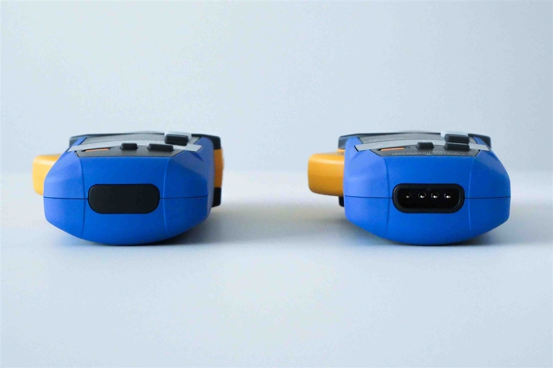
The connector at the bottom of the CM4003 allows for a special adapter cable to be connected to the meter. This adapter cable converts the 4-pin outlet of the CM4003 to these two connectors:

The external connector of the CM4003 does impact it's measurement category rating, which is CAT III 300V. In comparison, the CM4002 without the connector has a rating CAT IV 300V / CAT III 600V.
The adapter cable for the CM4003 leakage current clamp is called L9097 and it is included with every CM4003. The external USB power supply (Z1013) as well as the required USB-A-to-USB-C cable (L9510) are optional accessories. But again, the external power connector is a standard USB-C socket.
All three HIOKI CM400x leakage current clamps are available as bundle versions which have the Z3210 Bluetooth transmitter already included. These bundles are named CM400x-90.
So, whether you are looking for a small yet powerful AC leakage (and of course also load) current clamp like the CM4001, or whether you prefer a AC leakage current clamps with superb technical specifications or even an external output of the measured current - HIOKI's CM400x series will cover your needs.