element14 Community
element14 Community
    Register Log In
  • Site
  • Search
  • Log In Register
  • Community Hub
    Community Hub
    • What's New on element14
    • Feedback and Support
    • Benefits of Membership
    • Personal Blogs
    • Members Area
    • Achievement Levels
  • Learn
    Learn
    • Ask an Expert
    • eBooks
    • element14 presents
    • Learning Center
    • Tech Spotlight
    • STEM Academy
    • Webinars, Training and Events
    • Learning Groups
  • Technologies
    Technologies
    • 3D Printing
    • FPGA
    • Industrial Automation
    • Internet of Things
    • Power & Energy
    • Sensors
    • Technology Groups
  • Challenges & Projects
    Challenges & Projects
    • Design Challenges
    • element14 presents Projects
    • Project14
    • Arduino Projects
    • Raspberry Pi Projects
    • Project Groups
  • Products
    Products
    • Arduino
    • Avnet Boards Community
    • Dev Tools
    • Manufacturers
    • Multicomp Pro
    • Product Groups
    • Raspberry Pi
    • RoadTests & Reviews
  • Store
    Store
    • Visit Your Store
    • Choose another store...
      • Europe
      •  Austria (German)
      •  Belgium (Dutch, French)
      •  Bulgaria (Bulgarian)
      •  Czech Republic (Czech)
      •  Denmark (Danish)
      •  Estonia (Estonian)
      •  Finland (Finnish)
      •  France (French)
      •  Germany (German)
      •  Hungary (Hungarian)
      •  Ireland
      •  Israel
      •  Italy (Italian)
      •  Latvia (Latvian)
      •  
      •  Lithuania (Lithuanian)
      •  Netherlands (Dutch)
      •  Norway (Norwegian)
      •  Poland (Polish)
      •  Portugal (Portuguese)
      •  Romania (Romanian)
      •  Russia (Russian)
      •  Slovakia (Slovak)
      •  Slovenia (Slovenian)
      •  Spain (Spanish)
      •  Sweden (Swedish)
      •  Switzerland(German, French)
      •  Turkey (Turkish)
      •  United Kingdom
      • Asia Pacific
      •  Australia
      •  China
      •  Hong Kong
      •  India
      •  Korea (Korean)
      •  Malaysia
      •  New Zealand
      •  Philippines
      •  Singapore
      •  Taiwan
      •  Thailand (Thai)
      • Americas
      •  Brazil (Portuguese)
      •  Canada
      •  Mexico (Spanish)
      •  United States
      Can't find the country/region you're looking for? Visit our export site or find a local distributor.
  • Translate
  • Profile
  • Settings
Intelligent LED Solutions
  • Products
  • Manufacturers
  • Intelligent LED Solutions
  • More
  • Cancel

Intelligent LED Solutions

  • Blog
  • Forum
  • Documents
  • Events
  • Polls
  • Files
  • Members
  • Mentions
  • Sub-Groups
  • Tags
  • More
  • Cancel
  • New
Join Intelligent LED Solutions to participate - click to join for free!

Intelligent LED Solutions logo

Welcome to the ILS page on element14! 

Here to assist with your opto-electronic needs - we are a franchised stocking distributor and agent for amsOSRAM, OSRAM Digital Systems, LEDiL, Stanley, and TSLC.

Check out our full offering in Farnell here.

Featured Video
$wikiData.Body()
Have a Question?
Related Products
Offering a unique and wide range of high quality LED-based products including Strips, Coins, PowerStars, Floods, and Flexible Strips. From visible spectrum wavelengths, Infrared (810-940nm), and Ultraviolet (200-400nm), we have a solution for you. We also offer an ever-expanding range of LED Drivers, Heatsinks, Lenses and Thermal Interface Material, so you can have a complete solution.
LED modules including PCB boards, power supplies, IR, UV
Latest News
  • OSRAM DS Driver Families from Inventronics

    OSRAM DS Driver Families from Inventronics

    sabrina.hobson
    sabrina.hobson

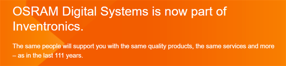
    In May 2023, OSRAM sold its LED Drivers, Lighting Controls, LED Flex, and LED Modules business to Inventronics. The new Inventronics will represent a forward-looking global enterprise, that is dedicated to meeting sustainability needs worldwide, as well as continuing to support you. But the OSRAM DS products you have come to rely on continue to be available and branded OSRAM, including OSRAM DS;

    • LED Drivers / Electronic Control Gears for indoor & outdoor
    • Light Engines and Modules for general illumination
    • LED Flex and Signage products
    • Lighting Control components and systems for general illumination

     image

    To experts and people in the “know” there are various families and terminologies for product families from Inventronics. Understanding what these mean and what the fundamental difference between them are, will help make finding the correct product for you easy. The main product family names you will have seen from OSRAM DS are:

    • Optotronic
    • Icutronic
    • Element

    Let us explore these further...


    Optotronic

    Optotronic products are high performance focused solutions. They offer numerous functionalities, making them suitable for a wide variety of applications with varying requirements including, tuneable white, ultra flat low profile, small profile (FIT products) and wireless (casambi), Dexal (D4i), and DALI. Although these products are typically at the higher price point, their functionality compared to other product families is far superior.

    Family focus: Innovation and outstanding performance.

    Portfolio: Standard and dedicated.

    Functionality:

    Parameter

    Available options

    Dimming

    DEXAL, DALI2,1-100%, PWM

    Dats Inside

    DiiA

    Interface

    NFC, LEDset2

    Performance

    Wide operating widows

    Lifetime

    5-8 years

    Functionality

    Touch Dim, CLO, EL


    Icutronic

    The Icutronic product family offers a great middle ground for customers. These standard products still have some key features that make them useful, but their versatility will be limited compared to the Optotronic product family. However, for customers who do not require all functionalities the Icutronic products can be ideal as the have a lower price point. Still designed to suit various applications, Icutronic LED drivers provide attractive performance and quality at a more cost-effective price range.

    Family focus: Standard.

    Portfolio: Standard.

    Functionality:

    Parameter

    Available options

    Dimming

    DALI2,10-100%, PWM

    Dats Inside

    N/A

    Interface

    Resistor

    Performance

    Standard operating widows

    Lifetime

    5 years

    Functionality

    CLO, EL


    Element

    Element family products our most affordable range. Ideal for specific applications and excellent value for money. Element drivers are remarkably simple (on/off) products, and perfect for customers not requiring dimming functions and for whom cost is a critical consideration.

    Family focus: Affordable.

    Portfolio: Standard (limited choice).

    Functionality:

    Parameter

    Available options

    Dimming

    N/A

    Dats Inside

    N/A

    Interface

    Dipswitch, Fixed

    Performance

    Dedicated currents

    Lifetime

    3 years

    Functionality

    N/A

    • 13 Aug 2024
  • What is a chip scale package LED? And how does it differ from a chip-on-board LED package?

    What is a chip scale package LED? And how does it differ from a chip-on-board LED package?

    sabrina.hobson
    sabrina.hobson

    Light emitting diodes (LEDs) are notorious for their high efficiency and long lifetimes. A diode is a semiconductor component which emits light in response to an electrical current being passed through it. The LED chip, when triggered by electrons, is responsible for the emission of light. It consists of semi-conductor layers that enable electrons and protons to move easily through. When this occurs the chip emits a blue light which is then converted by a layer of phosphor into various other wavelengths to produce the desired colour output.      

    LED technologies continue to develop, allowing for smaller packages to be produced. A LED package refers to the protective layer, typically plastic, that encases the LED chip and phosphor. This layer is responsible for focusing the light emitted, as well as helping with the transfer of heat from the LED chip to a heatsink. The most common LED packages on the market are chip-on-board (COB) or chip-scale-package (CSP). Each variation has its own benefits, but both are successful configurations of LED chips on a substrate. 


    Chip-scale-package (CSP) LEDs:

    A chip scale LED package typically has an equal size to the LED chip, or no larger than 20% of that. They are being increasingly implemented in various lighting designs. Therefore, versatility is further increased, as a CSP LED does not require soldered wire connections, as its component features are integrated. Thus, removing the need to directly secure the LED chip to the PCB by sub-mounting. These chip structures guarantee that 70% of the elements within a COB LED are not present in its form factor. This means that thermal resistance between the LED chip and PCB is reduced, as there is improved heat dissipation from the LED chip to the heatsink, giving CPS LEDs a more robust form factor.

    But a main drawback with CPS technologies is their cost. CPS LEDs are typically more expensive than COB LEDs.  Yet, other advantages of CSP technology include:

    • High lumen output. When compared to COB LEDS, CSP LEDs typically have higher illumination uniformity. CSP LEDs tend to have a visibility angle of around 180degrees. This helps add to the high lumen levels the LED emits.
    • Wide range of applications. CSP LEDs can be easily implemented in compact devices due to their compact size.
    • Flexibility in substrate material. Because the type of substrate material is not essential to the LED functionality, manufacturers can use various materials assuming it still has the desired properties. This allows for more cost-effective or readily available substrates to be chosen, there is flexibility in this choice. Whereas a COB LED will require particular substrate materials.


    Chip-on-board Package (COB) LEDs:

    A chip-on-board package consists of multiple LED chips mounted on a substrate material and coated by a uniform phosphor coating. This layer also works as a protective casing. This process is known as encapsulation. A common material used to do this is silicone epoxy.

    A COB LED differs most clearly from CPS LEDs in the way the LED chip is mounted. A COB LED will be directly mounted onto the surface of the PCB, or a thermally efficient substrate material. Whereas CPS LEDs do not require soldered wire connections. By directly mounting COB LEDs to the substrate surface, the density of the chips is increased, leading to a brighter light source. For example, in applications like LED displays, this enables a high pixel density.

    A key drawback of COB LEDs in comparison to CPS LEDs is their larger package size. But it is also worth noting that COBs like many other LEDs require adequate heat management. More than 70% of electric current delivered to LEDs converts into heat whilst only about 30% is converted to light emission. The placement of the LED chips within a COB LED package is very compact, and so heat management is essential for proper and effective LED operation.

     Yet they have many other advantages, including:

    • Large form factor. Although COB LEDs tend to be larger than CPS LEDs, they are still typically smaller than standard surface mount device LEDs (SMDs). Because of the technology involved in SMD LED mounting to a substrate, SMD LEDs tend to be a larger package.
    • Cost-effective. The energy consumed by a COB LED is about half that of an incandescent bulb. Furthermore, a COBs generate about twice as much light output. They have a higher efficiency in power consumption, that does not compromise luminance and quality of light.
    • 6 Aug 2024
  • All you need to know about LCDs

    All you need to know about LCDs

    sabrina.hobson
    sabrina.hobson

    The industry of displays is one that has rapidly grown and developed. Liquid crystal displays (LCDs), particularly monochrome LCD graphic modules have persevered and remains a popular choice in a variety of applications, due to their reliability and cost-effectiveness. In your day-to-day life, you most likely come across several of them. From the display on your home thermostat to the one on your oven or microwave. LCD displays are everywhere.

    In short, an LCD is a flat panel display that operates by using liquid crystals to create imagery on a screen. If you are involved with optoelectronics and display, then understanding LCDs, how they work and how they compare to other display technologies is vital. Maintaining and choosing new displays becomes simpler with this knowledge.

    Monochrome LCD means that the display consists of a single colour LCD panel to display graphical content, thus unlike colour TFTs, which use RGB pixels, monochrome LCDs use a single colour pixel.

    What are liquid crystals?

    Firstly, you need to know what is meant by liquid crystals. Liquid crystals, as the name implies, are closer to a liquid state than a solid one. Their characteristics are between that of a conventional liquid and that of a solid crystal. Meaning that it does ‘flow’ as a substance, but the individual molecules carry a crystal-like solid orientation.

    Liquid crystals are very sensitive to temperature. They are formed through a vast amount of heat, and it would only take a little more heat to turn liquid crystals into a real liquid. This is why LCDs can play up in extreme weather conditions.

    How do LCDs work?

    Within an LCD, liquid crystals are embedded in the screen. These are what work to produce an image of sequence on the display. Though it is important to note that liquid crystals do not produce light themselves. In illuminated LCDs, the light is emitted from a backlight which illuminates the liquid crystals. They operate by controlling the transmission of light through the liquid crystals.

    So, to form imagery on the display, voltage is applied to specific pixels in the liquid crystal layer. This causes certain liquid crystals to align in a specific direction, altering the quantity of light that is transmitted through the display. By varying the voltage, the amount of light passed through can be controlled, allowing different shades of the monochrome colour to be created.

    Polarized light denotes light waves with vibrations occurring in a single plane. In LCDs, this is accomplished by implementing polarized layers, with tiny nematic (twisted) liquid crystals positioned between the filters. Each pixel has polarizing filters on both the front and back. Polarizing filters dictate what light passes through the LCD screen and enable a better contrast ratio. Without these filters, the visual results of the display will have poor quality. Monochrome LCDs tend to have higher contrast ratios and faster response times than colour displays, making them ideal for applications requiring simple text and graphics.

    When the liquid crystals are off, electricity is not being passed through to the crystals from the transistors. This causes the crystals to appear brighter because of the 90-degree twisting of the nematic liquid crystal. This enables light to travel through both polarizing filters on the pixel. In this way, the pixel appears illuminated because of the light passing through.

    Comparatively, when the liquid crystal is switched on, electricity is being passed through the nematic liquid crystals, causing them to straighten out from their twisted state. The effect of this is that the polarizing filter in front of the liquid crystal blocks out the light. This leaves the pixel dark, in its switched-off state.

    Backlights

    As mentioned, liquid crystals do not emit light. A backlight is used for illumination in LCDs. LCDs can operate without a backlight, for example, pocket calculators where users need natural light to visibly perceive the information displayed on the screen. This makes them a more-energy efficient display technology as without a backlight they consume much less power than other display types. But in some more modern colour LCDs, a backlight will be installed behind the LCD panel to improve readability and aesthetics. The most common type of backlight is LED (light emitting diodes) based. LED semiconductors release photons and emit light after an electric current flows through them.

    Lifetime

    As with many other display types such as OLED and TFT, an LCDs lifetime will depend on serval factors, mostly relating to the conditions the device is stored in and used in and frequency of use. One benefit of LCDs over these other displays, is their extended lifespan, which have less frequent need for replacement.

    But an LCD device is only as strong as its weakest component. The lifetime and durability of the backlight is usually the most influential component in determining an LCDs lifetime. When the backlight reaches the end of its lifetime, it will dim, making the whole LCD appear to diminish.

    Learn more about TFTs here

    Learn more about OLEDs here

    Do you have another query? Contact us at info@i-lcd.co.uk

    image

    • 30 Jul 2024
  • Your LED Driver Questions Answered...

    Your LED Driver Questions Answered...

    sabrina.hobson
    sabrina.hobson

    What is the difference between constant current and constant voltage LED drivers?

    The main difference between the two is in how they regulate and deliver electrical power to the connected load. A constant voltage (CV) driver regulates a specified output voltage and supplies a fixed voltage output to the electronic circuit. CV drivers are ideal when a steady voltage level is required, as they allow the current to vary based on the load’s requirements. This is particularly beneficial in applications where the total quantities of LEDs are unknown or where additional control is needed. 

    Whereas a constant current (CC) driver will regulate a specified output current and are more suited to applications where the load requires a fixed current. They use a variable voltage to maintain a constant electrical current output. This works by the driver ensuring that the current flowing through the load remains steady, even if the load's resistance changes. In this way, CC LED drivers typically offer better control and a more efficient circuit than CV drivers. LED circuits using CC drivers easily connect the driver’s output directly to LEDs without added regulation. This is possible because the LEDs respond directly to the current driven through them.

    Learn more about the differences here.

    How to know which driver to choose.

    Choosing a suitable driver for your application can be tricky. There are many variables to consider, but typically the best driver for any given design will depend on the load and the application. The application will indicate which features are required and ultimately which driver will be best suited. Other factors to consider include, IP rating, dimming functionality, wireless, output current, CV or CC, output power, output voltage, dimensions, and lifetime.

    Learn all you need to know to select a driver here. 

    What is a constant power driver?

    Compared to standard constant current drivers, constant power drivers allow for more flexibility of design. While constant current drivers de-rate as the output current decreases, in a constant power driver the output current can be altered. As output current setting are reduced, the LED driver can produce a higher output voltage, enabling the circuit to take full power from the LED driver in a range of different output current settings.

    What are PF and PFC and why they matter in LED drivers?

    PF is the abbreviation for power factor and is expressed as a number between 1 and 0. It represents the ratio between actual power and apparent power in an AC (alternating current) power system. Apparent power is the product of the load voltage and load current. If the current and voltage are out of phase, then this could be notably larger than real power.

    To maintain a high-power factor, LED drivers must implement power factor correction (PFC). This will reduce the amount of current drawn by an electrical system. This is achieved by locally producing reactive power (KVAr). In turn, this lowers the current drawn from mains. This is vital to consider when selecting LED drivers, because LEDs typically have a low PF which mean that they draw more current than high PF loads, for the equivalent amount of real power transferred. Ultimately, meaning that less power is used, making it more cost-effective and producing a lower carbon footprint.

    Numerous standards are currently in place to regulate power factor correction in switch mode power supplies and LED drivers.

    What is the difference between lifetime and MTBF?

    MTBF stands for mean time between failure, and it refers to the statistical average of time that a LED driver should successfully operate for, before a repairable failure is likely. It does not represent the full expected lifetime of a LED driver. MTBF is useful to convey the reliability of a product. The higher this metric, the longer between technical failures and thus the more reliable the system will be. The MTBF is only relevant during the operating life of a LED driver.

    Whereas a product’s lifetime represents the length of time between initial use of a LED driver and the beginning of the wear-out phase. Essentially the entire time period that the product is predicted to last when operating under normal conditions. The lifetime of a product will be determined by the weakest component inside the unit with the shortest life expectancy. For LED drivers, electrolytic capacitors typically have the shortest life expectancy. While LED drivers typically have long life expectancies compared to traditional lighting components, it's essential to consider factors such as quality, operating conditions, usage patterns, and maintenance practices to maximize the lifespan and reliability of the LED driver in your application.

    What is potting (encapsulating) and why is it important?

    Potting refers to the process of encapsulating electronic components in a protective material to protect them from environmental hazards, mechanical stress, thermal issues, electrical faults, and corrosion. Typically, the material used is an epoxy resin or silicone. The protective coating acts as a crucial barrier to safeguard components from damage caused by things such as moisture, dust, vibration, and temperature fluctuations. Overall, this works to ensure reliable and long-term operation of a system to its full lifetime. Potting LED drivers can increase their durability, making them suitable for a variety of applications, including indoor and outdoor environments.

    What is the difference between DALI and DALI-2?

    DALI, or Digital Addressable Lighting Interface, first originated in the 90s in relation to ballasts, and in 2002 was promoted to an international standard for lighting communication protocols and interoperability. This certification and promotion were driven by DALI AG under the ZVEI, German Electrical and Electronic Manufacturers Association. It is now governed by the DALI Alliance, formerly known as the Digital Illumination Interface Alliance (DiiA).

    Since then, DALI has continued to develop in line with today’s technologies and the standard has grown as the lighting industry has matured and developed. In 2020 DALI-2 was introduced as the new standard (defined by IEC62386), constructed to fill gaps within the original standard. The creation of this new generation of DALI provides greater interoperability, more stringent test protocols and extended commands when compared to the first generation of DALI. DALI-2 includes standardisation of control devices, including light sensors, push buttons and occupancy sensors. DALI-2 is now widely available and utilised in many power control products on the market today. Any devices compliant with the DALI-2 standard will carry the DALI-2 logo.

    About Inventronics: In May 2023, OSRAM sold its LED Drivers, Lighting Controls, LED Flex and LED Modules business to Inventronics. These products continue to be branded OSRAM but are now owned, designed, manufactured, and developed by Inventronics. ILS is a gold standard sales partner of OSRAM DS and Inventronics. 

    image

    • 23 Jul 2024
  • Choosing the correct TFT display

    Choosing the correct TFT display

    sabrina.hobson
    sabrina.hobson

    TFTs, or thin film transistors, refers to an active-matrix LCDs (liquid crystal displays). They are known for their resilience and versatility and have revolutionised how information can be presented across multiple applications. Choosing a TFT involves several considerations, and depending on the end application, the importance of particular factors will vary. Successfully meeting these requirements will be fundamental to ensuring you have an effective, efficient, and attractive end design.

    So, what to consider…

    Size

    A good place to start is knowing your size requirements and limitations. TFT size is measured as the diagonal length of the display. Size considerations not only include physical space the outer dimensions of the TFT must fit, but also the size of the TFT's active area. The active area of a TFT is the display window on that is responsive and where change can be actively made.

    Brightness

    When selecting a TFT, brighter doesn’t always mean better. TFT brightness will be determined by the environment in which it will be situated. When indoors, suitable brightness is more likely to be around 300nits, as the display does not have to compete with sunlight. When outdoors, brightness would be more effective at 500nits, or even 1k nits if in direct sunlight, so that the display can still be perceived clearly. If the TFT is brighter than it needs to be for the desired setting, the module may show signs of visual fatigue, and diminished contrast between pure black and pure white, affecting the performance of colour and grey scale. It is worth noting that within the TFT parameters, there are varying technologies influencing brightness; TN, STN, Reflective and IPS governing the basics, but optical enhancements such as circular polarizers, O-film and anti-reflective coating amongst others also effect brightness. Even adding a touch screen can affect brightness, reducing it by up to 20%.

    Viewing angle

    This is determined by the TFTs LCD type. The wider the viewing angle, the larger the range at which the image on the screen can still be viewed clearly. This is enabled by the alignment of the liquid crystals within the display. They are aligned horizontally, which means that light can pass through them more easily. This results in less ‘glare’ on the screen as well as a widened viewing angle.  Often TFTs have about a viewing angle of around 140 degrees, but this can be higher. For instance, when implementing contrast enhancement mechanisms with IPS technology which offers 170-degree viewing capability. 

    Interface

    Multiple types of TFT display interfaces have been designed in recent years for all variations of display size. Some common interfaces include HDMI, RGB, LVDS, MIPI, SPI, RS232 and Parallel MCU. Newer technologies like eDP are also becoming more common. Choosing the best interface once again relies heavily on what the end application is. The choice will be guided by the resources on your application, as they each put different demands on time and system requirements.

    Temperature

    Like brightness, the required temperature range for a TFT will be determined by the operating environment. TFTs are sensitive to ambient temperature conditions. Typically, the recommended working temperature for a TFT is 0 to 50°C and -20 to 60°C for storage. However, when operating in outdoor environments, the TFT may experience more complex temperature variations. So more commonly now manufacturers offer variants that operate at -20 to +70°C. In summer, the ambient temperature can exceed 60°C, whilst in winter, it could fall below -20°C. If the temperature becomes too cold, the viscosity of the liquid crystal fluid within the TFT will decrease causing an increase to response times. Comparatively, if a TFT becomes overheated, damage to circuit board components can occur. There are additional techniques and mechanisms that can be explored to enhance TFT performance in extreme temperatures.

    Contrast ratio

    This is a key factor for optical performance. A better contrast ratio will create an image that is more layered, with the light and dark are clearly distinguished. This is more aesthetically pleasing to users and makes the display image easier to perceive, particularly when under dark conditions. Most deficits in contrast ratio occur in high ambient light. There are mechanisms available to manage this parameter, including timing control (TMR) internally, and surface coatings like AR (anti-reflection and for outdoor conditions optical bonding).

    Touch requirements

    In a growing technological world, both intelligent user interfaces and touch functions are being a prerequisite for many new product designs. Therefore, TFT touch enhancements have become more cost-effective. TFT touch screen works with either capacitive or resistive technologies. Capacitive touch screens use an overlay of conductive material that senses a user's touch. Whereas resistive touch screens have two layers separated by a small gap, which detects pressure when pushed.

    Cover lens and optical bonding

    A cover lens is bonded to the display and protects it from scratches, dirt, and UV radiation. So, if choosing a TFT for a high-intensity and hard-wearing application, this may be needed to prevent damage. The size and thickness of the cover lens will determine the level of protection it provides the display. Optical bonding can be used alongside a cover lens to significantly reduce any internal reflections produced between the cover lens, and display layers by filling any air gaps between the layers with an optically clear adhesive.


    Unsure what your requirements are? Get in touch with us today.

    Info@i-lcd.com      01635 294600

    image

    • 16 Jul 2024
  • Different purposes of light in horticulture

    Different purposes of light in horticulture

    sabrina.hobson
    sabrina.hobson

    The use of light in horticulture has vastly increased in recent years. Knowledge of how light affects crops is still evolving, but what is clear is that light can benefit both crop health and yields. Different wavelengths have varying benefits and purposes in horticulture, thus the versatility that LED technologies offer is ideal.

    Plant growth and yields.

    One of the most common reasons that growers implement horticultural lighting is to increase plant yield, speed and widen growing windows. Artificial lighting is particularly useful in applications where natural sunlight is lacking. For example, in greenhouses on overcast days or during the winter months when sunlight hours are shortened. By using horticultural lighting, growth opportunities have expanded, and crops can be grown within conditions that were not previously viable.

    • Sole-source lighting: More commonly growers are getting creative with where they can grow crops. In urbanised areas, vertical farms have been gaining traction, such applications can be entirely indoors without access to natural sunlight. Sole-source lighting refers to the delivery of light to plants that do not also receive light from the sun. For artificial lighting in such settings, growers are turning to LED, which provide multiple benefits, whilst minimising ongoing running costs.
    • Supplemental lighting: This style of light implementation works alongside natural daylight to supplement and provide additional light to crops. This could be by delivering a full spectrum of wavelengths outside of natural growing hours to increase the growing window. Or by providing plants with additional quantities of specific key wavelengths during natural daylight hours to increase their positive effects on the quality of plant growth. This method is often used for crops that need lots of light, like tomatoes, grown in greenhouses, particularly during winter months.
    • Photoperiodic lighting: This method is more application-specific, as it does not typically encourage photosynthesis and plant growth. Rather, it promotes and regulates flowering and certain phases of plant development. This is useful for ornamental crops, such as those used in landscaping. With lighting, growers can encourage these plants to produce flowers when desired, by providing low-intensity light to plants that mimics natural light and dark cycles.

    The Treviso grow light is designed for easy installation in vertical farms, racks, and benches. With a full spectral output, plants can be exposed to multiple wavelengths to assist with plant quality and growth speed. The built-in lens provides a 120-degree coverage, meaning that large areas can be illuminated with a single light. Treviso is an ideal replacement for traditional T5/T8 lamps.

    Learn more about the effects and benefits of different light wavelengths here: full spectrum light, red light, and blue light.

    Sterilisation and removal of harmful bacteria.

    Perhaps less commonly discussed, are the benefits and applicability of light for plant sterilisation and the removal of harmful bacteria. No matter what the crop, growers all encounter the common issues of pests and disease, including black spots, powdery mildew, and grey mould. For decades, growers have been using chemical pesticides to protect plants from such problems. But these chemical contents of these solutions can have a negative impact on the natural soils and water supplies. Moreover, regular use of pesticides could lead to contamination of the plants themselves.

    So now, UV light can be applied directly to plants to combat these issues and destroy harmful bacteria and pathogens, without negatively impacting the plant itself. Plants consist of organised multilayer tissues, whilst pesty problems structurally differ. Fungi, for example, consist of mono-layered mycelia. Bacteria have significantly less complex structural organisations, as many are single-cell. So, when UV is applied the effects on such micro-organisms in comparison to the plant itself fundamentally differ. Fungi and bacteria will be destroyed, leaving the plant be. Though caution is still needed, as too much exposure to UV radiation can still burn and damage plants. The wavelength applied and duration of exposure should be tailored based on the plant’s specific needs.

    UV wavelengths can even be applied to plant water supplies for additional sterilisation. When applied to water, UV light will not alter the pH or chemistry of the water, but it will neutralise any harmful organisms to growers such as fungi, viruses, moulds, and mildew. 

    The Amalfi disinfection light allows for efficient sterilisation, eliminating 99.9% of bacteria, spores, and viruses in only 10 seconds. An ideal solution for protecting target plants from diseases and pests. The Amalfi combats powdery mildew, funguses, viruses, and bacteria on plants.

    Learn more about the effects and benefits of ultraviolet wavelengths here.

    • 9 Jul 2024
  • All you need to know about TFT displays

    All you need to know about TFT displays

    sabrina.hobson
    sabrina.hobson

    Known for their resilience and versatility, TFT displays have revolutionised how information can be presented and managed across multiple industries. TFT stands for thin film transistor, and in displays, this refers to an active-matrix LCDs (liquid crystal displays). They are being used more frequently in new applications and designs, as they enable a better visual presentation and user experience. In comparison to standard passive matrix LCDs, a TFT provides very sharp images with shortened response times. Plus, TFTs consume less power than other display types, making them energy efficient.  

    How do TFTs work? 

    In short, TFTs are flat panel displays which use thin film transistors to control the individual pixel's brightness and colours. The structure of the display is sandwich-like, with the TFT layer in the middle. At the base, there is a backlight which is the light source, this is then followed by the TFT layer which controls the light flow through the display, and a colour filter dictates the colour. Finally, a top layer of glass houses the visible screen. Touch panels can then also be added on top of this to increase capabilities in certain applications. 

    image

    The TFT acts as switches that pass the correct voltage onto the relevant liquid crystals to dictate whether these pixels are lit (on) or dark (off). The TFT are the active elements within the display. The electrical charge received by the liquid crystal pixels causes them to alter their molecular structure, allowing the varying colour wavelengths of the backlight to ‘pass-through’. 

    The TFT layer of the display is arranged in a matrix. The characteristics of the pixels within this are determined by the underlying density (resolution) of the colour matrix and TFT layout. The more pixels the higher detail is available. Each pixel within the TFT is paired with a transistor. Each transistor contains a capacitor, which allows each individual sub-pixel to retain its charge, rather than needing a new electrical charge to be sent each time it needs to be changed. This technology enables a display that operates using minimal energy, without running out of operation. A TFT is in constant flux and refreshes rapidly depending upon the incoming signal from the control device. 

    What are the applications and benefits? 

    TFTs are very versatile and resilient and, therefore have a vast number of applications. These displays are designed to withstand physical shock and vibration, as well as to be protected against environmental elements such as water and dust exposure. In the most physically demanding applications, they can also be housed in robust enclosures to enhance their durability even more.  

    Most commonly you will find TFTs in mobile devices, computer screens and some TV’s. But due to their high readability performance, they are suited to outdoor use as well as indoor. The high levels of brightness and contrast mean that they can still be readable even in direct sunlight. For outdoor applications where visibility is paramount, particularly in emergencies, this is ideal. An operator can easily monitor a system's status with clarity through a TFT. 

    TFTs are also known for having a wide temperature range, which increases their functionality in diverse climates. They are engineered to function in temperatures from the bitter cold (-30℃) to the scorching hot (+85℃).  

    All these factors contribute to the impressive longevity of TFTs. They have long lifetimes which for users means minimal maintenance is required, as well as reduced need for replacement and repair costs. This adds to their popularity in remote applications and hard-to-reach installations.  

    What are the limitations? 

    • Due to their design and more advanced technology, TFTs are currently more expensive than standard monochrome displays, and even some OLED displays. 
    • Although TFTs do provide an overall good contrast, the contrast ratio is still slightly limited. They often struggle to display deep blacks and bright whites simultaneously.
    • Unlike other display technologies like OLED, TFT screens cannot emit their own light, they do still require a backlight to generate the display imagery. 
    • Similarly with viewing angles, although TFTs have much better viewing angles than standard LCDs, when viewing from extreme angles this is still limited, and the image quality can appear degraded. If working in an application where viewing angle is key, IPS options could be considered, as these typically offer 85 degrees viewing from all angles.
    • TFTs are susceptible to image retention, which can eventually cause ghost images to appear on the display screen.
    • 2 Jul 2024
  • Phasing out fluorescent tubes: Moving to sustainable lighting solutions

    Phasing out fluorescent tubes: Moving to sustainable lighting solutions

    sabrina.hobson
    sabrina.hobson

    In recent years, the lighting market has shifted towards energy-efficient and sustainable solutions. Many governments and organisations across the European Union (EU) have been promoting more sustainable lighting technologies. The UK has followed suit and introduced a ban on these older lighting technologies including compact fluorescent lightbulbs (CFLs). Inefficient traditional incandescent and CFL lighting solutions have become increasingly unavailable. Which is no surprise based on their notoriously short lifetimes and high energy consumption levels. 

    image

    CFL technologies on average use about 75% less energy than incandescent lighting solutions. Thus, CFL lighting was initially introduced to the market as a more energy-efficient alternative. With their longer lifetimes and reduced energy consumption, they became a popular choice for businesses and consumers across the EU and UK. This popularity was furthered even more in 2009 by a ban on traditional incandescent light bulbs introduced by the EU. Which was implemented as part of the EU’s pledge to decrease carbon emissions and tackle climate change. 

    However, though widely implemented, and better than incandescent lighting, CFL technologies still had many drawbacks which have led to their own phasing out in today’s lighting market. CFL technology is now outdated and relies on the inclusion of hazardous materials such as mercury. Mercury is toxic and can be harmful to both humans and our environment. So, to lessen these risks and withdraw such energy-demanding products from the lighting market, the EU chose to phase out CFL lighting. So, in 2023, CFLs and T5 and T8 fluorescent were phased out to align with the new European Commission's Eco-design and RoHS Directives.  

    This has left the market to turn to an even more energy-efficient and environmentally friendly lighting solutions: Light emitting diodes (LEDs). LED modules and bulbs are widely replacing fluorescent lights. Making this switch can provide instant benefits, reducing carbon emissions and future waste, whilst also increasing operational and cost efficiencies. In comparison to fluorescent lighting, LEDs have much longer lifetimes, greater energy efficiency, and do not contain mercury that poses a risk to consumers and our environment. The absence of such toxic substances is in accordance with the EU’s commitment to decreasing the use of hazardous materials. 

    Now that LEDs are championing the market and enabling a more energy-efficient world, there is a significant decrease in energy usage in multiple market sectors. This is helping protect our environment on a larger scale, whilst also decreasing electricity bills for consumers. These impacts can be seen across varying sectors of the lighting market, including horticultural lighting. In previous years fluorescent tubes were a popular choice for indoor growers. Learn about the benefits of LED grow lights over fluorescent solutions here.  

    Overall, the ban on fluorescent and CFL light bulbs has positively progressed the lighting market in a way that consumers and business continue to reap benefits from. The new UK and EU regulations have prompted movement towards a more sustainable future. Plus, with continuing developments and advancements in LED technology, lighting will only continue to improve and become more price-accessible to the wider market.

    • 25 Jun 2024
  • All you need to know about OLEDs

    All you need to know about OLEDs

    sabrina.hobson
    sabrina.hobson

    If you have anything at all to do with tech, you will have come across OLED displays. Commonly used in TVs, tablets, and laptops, but how much do you really know about OLEDs? Well, here is all you need to know about how they work and their pros and cons.

    OLED stands for organic light-emitting diode. It is a carbon-based LED (Light Emitting Diodes) technology that greatly differs from standard LED technologies. Whereas standard LEDs are small single-point light sources made of semi-conductor layers, OLEDs are produced in sheets creating diffused-area light sources. OLEDs are typically thinner and brighter than standard LEDs, enabling more flexibility.

    An OLED is a solid-state device within which electrons and holes are produced from layers of carbon film, or ‘organic material’, that sits inside the OLED panel sandwiched between two thin-film conductive electrodes, behind the glass screen. When an electric current is passed through this layer of organic compound, it emits its own light. The light intensity will be determined by the amount of current applied by the electrodes. Operating in this way eliminates the requirement for a backlight, like those found in liquid crystal displays (LCDs). A standard LCD will typically have an LED backlight that sits uniformly across the entire back of the LCD screen.

    image

    For light to successfully pass through and emit out from an OLED, one of the electrodes must be transparent. Depending on the device this can be the anode or cathode. The colour of light emitted is established by the type and configuration of emissive material in use.

    1. Single-stacked: This is the simplest design and lowest-cost configuration. It only used 1,2, or 3 emitters to create colour and white light.
    2. Stacked: This method produces white light in every pixel and then applies a colour filter to create red, green, and blue sub-pixels. It is a slightly more complex structure than single-stacked and can increase the brightness of the OLED without needing to increase the current density.
    3. Side-by-side striped: Typically, the preferred approach for high-resolution displays such as on mobile phones. This configuration further allows for colour tunability. The sub-pixels red, green, and blue will sit side-by-side within each pixel of the display.

    image

    Because OLEDs are so thin and provide such sharp contrast with wide viewing angles, they are ideal for applications like TVs and mobile phones. OLED TVs provide higher image quality, as well as lower power consumption. In an OLED TV, the individual pixels produce light, and so when certain pixels are not needed, they can be individually turned off to achieve perfect blacks. OLED screens can even be curved, enabling all sorts of interesting applications such as LG’s ‘Wallpaper TVs.’ There is even ongoing research into creating transparent and flexible  OLED screens.

    OLED advantages

    • OLEDs offer a flexible solution that widens design possibilities. They can be manufactured into most shapes and sizes. As well as being mounted onto flexible substrates or transparent surfaces, to emit light from both sides of the screen.
    • Due to their lack of an external backlight, OLEDs are more energy-efficient to run than LCDs. Additionally, because individual pixels can turn off as needed, this means that OLED screens consume less power when operating.
    • OLED displays are very thin, enabling a more visually pleasing product as well as a lighter-weight solution which can be easily mounted to the desired surface.
    • Sharp contrast and crisp multi-colour displays can be achieved with OLED. True blacks are enabled, and fast smooth colour transitions. The diffused light emitted from OLED displays allows them to be used close to the top surface of the screen, without creating glare.

    OLED disadvantages

    • The lifetime of OLEDs is one of their key drawbacks. OLED lifetime is greatly reduced at elevated temperatures, it is much more suited to low ambient conditions. This is made more complex as a lifetime of pixels can differ depending on the assorted colour usage. Blue colours tend to have a lower lifetime than other colours such as yellow, which can lead to having to replace displays more frequently than desired.
    • Sticky pixel (also known as image retention) occurs when an image or sequence is repetitively played on a screen. It refers to the permanent mark that can be left by damaged pixels caused by this repetitive use. Although this only typically arises when using a screen for a constant and continuous purpose such as display advertisement in a retail store. 
    • Another large drawback is the price of OLEDs. They are not cheap to produce, particularly when using more complex configurations. Because of this, realistically, OLEDs are still years away from widespread use for general illumination.
    • 12 Jun 2024
  • Common ultraviolet (UV) LED light applications

    Common ultraviolet (UV) LED light applications

    sabrina.hobson
    sabrina.hobson

    Ultraviolet light is electromagnetic radiation outside the visible light spectrum. It is a useful technology with multiple applications. Let us explore a few….

    UV curing

    Used in applications from manufacturing to dentistry, UV light can be used to cure a chemical substrate including various inks, varnishes, lacquers, and finishes. A high-intensity UV light cures these substances through polymerisation into instantly fixed-in-place solids. This provides products with a strengthened outer coating, which is beneficial to products needing increased durability to survive in demanding environments such as industrial, automotive, and aerospace applications. It is a popular curing method due to its instantaneous effect at a low cost and risk. Standard speeds for this process are around 1-30 seconds, with higher-intensity light leading to faster cures.

    Artificial tanning

    UVA radiation is the wavelength emitted by the sun that causes human skin to tan. This occurs as the UVA radiation penetrates through to the deep layers of the epidermis (skin), where they trigger melanocyte cells to produce melanin. Melanin is the brown pigment that causes tanning and occurs as the body’s natural defence to protect the skin from sunburn. Tanning salons utilise UV lamps to offer clientele a way to enjoy a suntan all year round, from man-made technology. However there are risks of over-exposure to UV radiation from stuff applications which should be considered.

    Medical - Phototherapy

    Medical applications are an interesting area utilising UV technology. UV radiation through phototherapy can have many medical benefits to a variety of skin conditions such as acne, jaundice, psoriasis, eczema and even conditions like seasonal depression and some skin cancers. The target areas will be exposed to the UV rays for short set time period, shutting down immune system cells in that area of the skin, triggering biological processes that minimise inflammation and prevent skin cells from generating and growing too fast.

    Germicidal sterilisation and disinfection

    Within this application, the most effective UV wavelengths used are UVC and UVB. Germicidal lamps and UVC LEDs (Light Emitting Diodes) kill bacteria on a targeted surface, as irradiating bacteria with UVC changes the helix structure of the DNA and RNA within those bacteria, inactivating them and disenabling their proliferation. Bacteria and viruses proliferate, by cell division based on genetic information, to cause infection and illness. DNA and RNA hold the genetic information necessary for this proliferation to occur. Today, UVC technology is the first choice for many industries that require water, air, or surface sterilisation, as it is a highly effective method. Learn more about it here.

    Black lights

    Often used in entertainment and decorative visual effect settings, such as nightclubs or amusement parks. When emitted UVA radiation gives off a light that is invisible to the human eye, but when this light bounces off certain surfaces' it appears to glow. This glow occurs when the emitted UV rays are converted into visible light by particles called phosphors that reside in certain surfaces and materials. Phosphors hit by UV rays become charged and naturally fluoresce, or in other words, glow. As well as recreational applications blacklights are also commonly used in forensic applications such as crime scene investigations. They can be an essential tool for forensic investigations by police to detect substances that may not be visually obvious to the human eye – most bodily fluids, bone and teeth are naturally fluorescent under a UV black light.

    See our UV range in Farnell here.

    • 11 Jun 2024
>
Documentation
  • sabrina.hobson
    Group Intro Content Widget
    By sabrina.hobson > > over 2 years ago

  • sabrina.hobson
    Main Group Widget
    By sabrina.hobson > > over 2 years ago

  • jdumais
    Setup
    By jdumais > > over 3 years ago

  • jdumais
    Documents
    By jdumais > > over 3 years ago

  • jdumais
    Polls
    By jdumais > > over 3 years ago

element14 Community

element14 is the first online community specifically for engineers. Connect with your peers and get expert answers to your questions.

  • Members
  • Learn
  • Technologies
  • Challenges & Projects
  • Products
  • Store
  • About Us
  • Feedback & Support
  • FAQs
  • Terms of Use
  • Privacy Policy
  • Legal and Copyright Notices
  • Sitemap
  • Cookies

An Avnet Company © 2025 Premier Farnell Limited. All Rights Reserved.

Premier Farnell Ltd, registered in England and Wales (no 00876412), registered office: Farnell House, Forge Lane, Leeds LS12 2NE.

ICP 备案号 10220084.

Follow element14

  • X
  • Facebook
  • linkedin
  • YouTube