element14 Community
element14 Community
    Register Log In
  • Site
  • Search
  • Log In Register
  • Members
    Members
    • Benefits of Membership
    • Achievement Levels
    • Members Area
    • Personal Blogs
    • Feedback and Support
    • What's New on element14
  • Learn
    Learn
    • Learning Center
    • eBooks
    • STEM Academy
    • Webinars, Training and Events
    • Learning Groups
  • Technologies
    Technologies
    • 3D Printing
    • FPGA
    • Industrial Automation
    • Internet of Things
    • Power & Energy
    • Sensors
    • Technology Groups
  • Challenges & Projects
    Challenges & Projects
    • Design Challenges
    • element14 presents
    • Project14
    • Arduino Projects
    • Raspberry Pi Projects
    • Project Groups
  • Products
    Products
    • Arduino
    • Dev Tools
    • Manufacturers
    • Raspberry Pi
    • RoadTests & Reviews
    • Avnet Boards Community
    • Product Groups
  • Store
    Store
    • Visit Your Store
    • Choose Another Store
      • Europe
      •  Austria (German)
      •  Belgium (Dutch, French)
      •  Bulgaria (Bulgarian)
      •  Czech Republic (Czech)
      •  Denmark (Danish)
      •  Estonia (Estonian)
      •  Finland (Finnish)
      •  France (French)
      •  Germany (German)
      •  Hungary (Hungarian)
      •  Ireland
      •  Israel
      •  Italy (Italian)
      •  Latvia (Latvian)
      •  
      •  Lithuania (Lithuanian)
      •  Netherlands (Dutch)
      •  Norway (Norwegian)
      •  Poland (Polish)
      •  Portugal (Portuguese)
      •  Romania (Romanian)
      •  Russia (Russian)
      •  Slovakia (Slovak)
      •  Slovenia (Slovenian)
      •  Spain (Spanish)
      •  Sweden (Swedish)
      •  Switzerland(German, French)
      •  Turkey (Turkish)
      •  United Kingdom
      • Asia Pacific
      •  Australia
      •  China
      •  Hong Kong
      •  India
      •  Korea (Korean)
      •  Malaysia
      •  New Zealand
      •  Philippines
      •  Singapore
      •  Taiwan
      •  Thailand (Thai)
      • Americas
      •  Brazil (Portuguese)
      •  Canada
      •  Mexico (Spanish)
      •  United States
      Can't find the country/region you're looking for? Visit our export site or find a local distributor.
  • Translate
  • Profile
TDK
  • Products
  • Manufacturers
  • TDK
  • More
  • Cancel
TDK
Documents How does the AC Fail signal work in a power supply?
  • Blog
  • Forum
  • Documents
  • Events
  • Members
  • Mentions
  • Sub-Groups
  • Tags
  • More
  • Cancel
  • New
TDK requires membership for participation - click to join
Actions
  • Share
  • More
  • Cancel
Engagement
  • Author Author: Nortski
  • Date Created: 2 Mar 2011 5:16 PM Date Created
  • Last Updated Last Updated: 7 Oct 2021 8:49 AM
  • Views 774 views
  • Likes 0 likes
  • Comments 0 comments
Related
Recommended

How does the AC Fail signal work in a power supply?

I was recently talking to one of our Design Engineers about my blog and he suggested a clarification of the operation of the AC Fail signal would be a good topic.  He stated that he was often asked “at what input voltage does the AC Fail signal operate?”


A power supply’s AC Fail signal is used to provide a warning to the user that the AC input power has either been lost, or is dropping in voltage to a point that the power supply will soon no longer be able to regulate or provide power.


Customers using such a signal will then have a short period of time (typically 5 to 10ms) in which to store any data or start an orderly shutdown of their system.


Internal to the power supply, the AC Fail circuit is usually a simple circuit comparing a reference with the voltage of a primary side housekeeping supply.  In the event that voltage drops, drive is removed from an opto-coupler and the user provided with an AC Fail signal state change.


Before the widespread use of Power Factor Correction (PFC), the AC Fail did indeed operate at a set input voltage.  I remember as a Test Technician reducing the input voltage with a variable transformer (variac) to check the function.


On those non PFC power supplies, the AC input is peak rectified as shown below.  The main switching converter operates off that unregulated high voltage buss, the value of which is a direct function of the AC input voltage – between 120 and 375VDC.
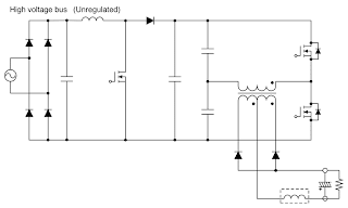
 

image
Click to enlarge


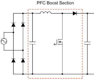
On power supplies with PFC though, that high voltage buss is regulated using a boost circuit – to around 360VDC.  Now any change to the AC input voltage (within the normal operating range) is not reflected in a change in the DC buss; hence a different test method must be used.


image


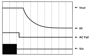
Use a storage oscilloscope to monitor the output voltage, the AC Fail signal and if desired, an isolation transformer to display the AC input voltage.


image


Turn off the input voltage and measure the time between the AC Fail signal going low and the output voltage starting to drop.  This is the amount of warning time you will have.


Unlike with a non PFC power supply, this warning time will not be related to input voltage.

  • ac_fail_signal
  • power_supplies
  • switchmode_power_supplies
  • tdk-lambda
  • Share
  • History
  • More
  • Cancel
  • Sign in to reply
element14 Community

element14 is the first online community specifically for engineers. Connect with your peers and get expert answers to your questions.

  • Members
  • Learn
  • Technologies
  • Challenges & Projects
  • Products
  • Store
  • About Us
  • Feedback & Support
  • FAQs
  • Terms of Use
  • Privacy Policy
  • Legal and Copyright Notices
  • Sitemap
  • Cookies

An Avnet Company © 2023 Premier Farnell Limited. All Rights Reserved.

Premier Farnell Ltd, registered in England and Wales (no 00876412), registered office: Farnell House, Forge Lane, Leeds LS12 2NE.

ICP 备案号 10220084.

Follow element14

  • Facebook
  • Twitter
  • linkedin
  • YouTube