Application Notes
USB 2.0 with REDFIT IDC SKEDD Connector
ANE014 BY STEFAN SCHILPP IN COOPERATION WITH GÜNTHER KLENNER FROM ![]()
1 Transmitting USB 2.0 signal with REDFIT IDC SKEDD Connector
During simple signal transmission from a USB to a flat ribbon cable, differential-mode interference occurs between the conductor and the data line. By simply adding two additional ground wires it is possible to convert differential-mode to common-mode interference, which can easily be eliminated with a data line filter. Combined with the advantages of SKEDD technology it is easy to realize highly cost effective and maintenance-friendly connections to USB interfaces.
The challenge for device developers is to find a way of connecting controls on the front of the housing to USB ports on the back of a device in a spacesaving and cost-effective way without reducing signal quality. If you look inside the housing, circuit boards are often connected with flat ribbon cables (Figure 1).
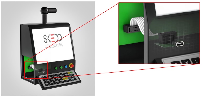
Figure 1: This fictitious machine control example shows the connection between the USB port on the front panel and the circuit board on the back of the panel via REDFIT IDC connectors and a ribbon cable.
The benefit of concealing them inside of housing is that they do not need the high level of shielding that is required by external cables, making them cheaper. This cost-effectiveness is the strength of the IDC connector with SKEDD technology (Figure 2). This technology does not require a mating connector on the circuit board and it can be manually connected to the circuit board (Figure 3).
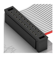
Figure 2: SKEDD technology saves connector sockets
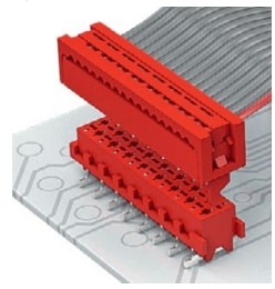
Figure 3: Conventoinal connector solution with counterpart
This solution not only saves space and height, but it is also incredibly economical. Only the holes for the connector need to be drilled and plated on the circuit board without the subsequent need for THT soldering to the mating connector. As double-sided assembly is possible and plugging and unplugging can be done without tools, a defective cable, for example, can be replaced very quickly. Insulation Displacement Technology (IDC) certainly offers additional time-saving advantages. (Further advantages of SKEDD Technology can be found in the ANE011 SKEDD Technology, Advantages and Application)
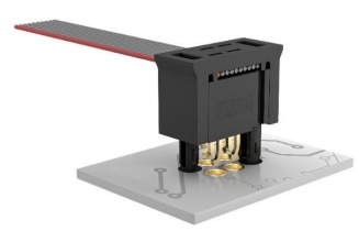
Figure 4: REDFIT IDC SKEDD connector with PCB
One problem with transmitting USB 2.0 via four ribbon cables is that ground, voltage and the data pair are subject to asymmetrical interference of the useful signal which cannot be suppressed. But should a loss of signal quality be acceptable simply because the connection needs to be positioned on the opposite side to the controls on the device? Not with the simple, yet clever idea from Würth Elektronik. It takes advantage of the fact that the IDC connector is also available with six pins and that an additional ground pair can be implemented to generate common-mode interference that a currentcompensated choke can filter.
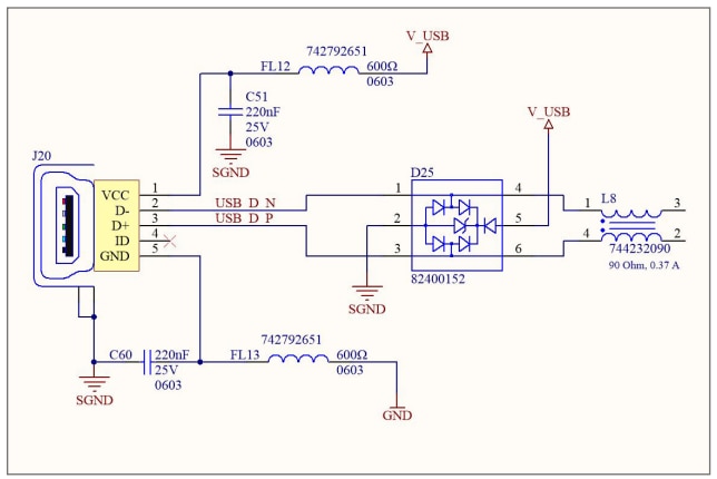
Figure 5: Example of USB input circuit with the 4 USB lines
2 Differential-mode changes to common-mode
When a USB 2.0 signal is transmitted via four flat ribbon cables (GND, D+, D-, VBUS), the current flows through the supply voltage wire and back through the ground wire in the opposite direction (Figure 6). Any power interference that arises due to load variations in the power grid couples from the supply wire into the adjacent D+ wire, and the corresponding disturbances on the ground wire couples into the D- wire. Power supply interference is transmitted through the data lines in differential-mode, not common-mode, and thus can no longer be suppressed. A solution to this is to use six wires (GND, D+, D-, GND, VBUS, GND) (Figure 7). Due to the arrangement of the wires, any interference on the ground wires next to the data pair runs in the same direction, i.e. coupling with the data pair occurs in common-mode. Interference that runs in the same direction can be very easily filtered using common-mode chokes. (for more information see also Application Note ANP024: The USB interface from an EMC perspective).
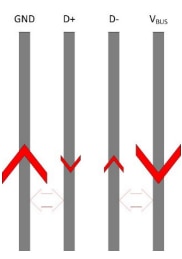
Figure 6: Common-mode interference arises from the fact that interference on the GND and VBUS wires couple into the neighboring wires D- and D+ in the same direction.
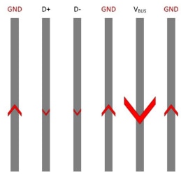
Figure 7: Because interference on the GND wires runs in the same direction, it also couples into the data lines in common-mode. This common-mode interference can be filtered.
3 Impedance determines cable length
USB 2.0 is defined by a maximum current of 1A. The same specification applies to flat ribbon cables and SKEDD-connectors. Nevertheless, transmitting USB 2.0 via a 6-wire ribbon is not unlimited. According to IPC-TM-650, ribbon cables with an asymmetrical structure (GND, D, GND) have an impedance of Z = 105 Ω. The USB 2.0 specification stipulates an impedance between 76.5 and 103.5 Ω for the cable when measured during differential transmission. However, since it is no longer an asymmetrical structure, impedance must be determined as differential version ZDD. If the value lies outside the USB 2.0 specification, the ribbon cable can only be used up to a certain length, and this depends on the transmission rate. The following impedance estimate, illustrated in Figure 8, explains the permitted length of the transmission link within the housing.
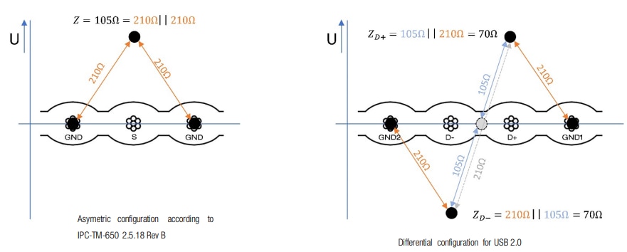
Figure 8: Transmission of asymmetrical impedance to a differential structure
Impedance of the data line of an asymmetrical, 3-phase ribbon cable is 105 Ω, i.e. the impedance of the two ground wires to the data line is 210 Ω each, since 105 Ω = 210 Ω || 210 Ω. Applying this principle to the two data lines and the surrounding ground wires of a 6-core ribbon cable, results in a virtual zero point between the data lines, i.e. a virtual ground. For series connections, 105 Ω lies between the virtual ground and the capacities of the D+ and D- lines, which is why GND1 with D+ and GND2 with D- can be regarded as two systems with an asymmetrical structure for which the following applies: ZD = 210 Ω || 105 Ω = 70 Ω. Because ZD- and ZD+ are opposed to each other, each with 70 Ω, the result is a ZDD of 2 x 70 Ω = 140 Ω, which exceeds the permitted range of the USB 2.0 specification. The difference of 50Ω between the line impedances of Z0 = 90 Ω (impedance of USB 2.0) and Z0 = 140 Ω (6-wire ribbon) transforms the load impedance of the ribbon side to just under 218Ω due to the incorrect adjustment. This is more than twice the required 90Ω, which means that there is an impedance adjustment of VSWR < 1:2,4 or a return loss <-7.5dB. this has to be considered for the data transfer rate.
4 Transfer rate depending on cable length
Cable lengths measuring around a meter are possible for full-speed transmission at 15 Mbps, since the base frequency is f1max = 7,5 MHz, and that of the 3rd harmonic wave f3max = 22,5 MHz (λ = 13,3 m). Combining a 6-core ribbon cable and an IDC connector with SKEDD technology is ideal for this type of application because there is no need to worry about impedance matching, for example. Another benefit of transmission with six wires is that there is always a ground connection from the perimeter wires. Any damage to the ribbon cable, which mostly occurs with the perimeter wires, exposes a ground connection but does not cause any data transmission interference if it comes into contact with the housing. In addition, a short circuit to ground is usually less dangerous than a short circuit to the voltage supply cable, which would be the case with the 4-wire version. Furthermore, an additional two ground wires help to minimize possible cross currents on the housing ground, which could quickly lead to EMC problems.
For a 480 Mbps high-speed transmission of a USB 2.0 signal as a square wave pulse is f1max =2 40 MHz. In order for the pulse to appear as a pure pulse rather than as sine, the proportions of the 3rd harmonic wave are needed that lie at f3max = 3x240 MHz = 720 MHz. The wavelength at this frequency is λ720 = 40 cm. The full transformation of impedance occurs at λ/4, i.e. at 10 cm. At λ/10 (=4 cm), however, the transformation is negligible. To enable the ribbon cable to be longer than 4cm, for high-speed transmission of USB 2.0 in the housing, only the base wave with λ240 = 120 cm is considered due to the impedance difference of 50 Ω. This results in a non-critical cable length of 12 cm. This roughly means that with a line impedance of ZDD= 140 Ω, secure data transmission is possible with a cable length of up to 10 cm.
IMPORTANT NOTICE
The Application Note is based on our knowledge and experience of typical requirements concerning these areas. It serves as general guidance and should not be construed as a commitment for the suitability for customer applications by Würth Elektronik eiSos GmbH & Co. KG. The information in the Application Note is subject to change without notice. This document and parts thereof must not be reproduced or copied without written permission, and contents thereof must not be imparted to a third party nor be used for any unauthorized purpose. Würth Elektronik eiSos GmbH & Co. KG and its subsidiaries and affiliates (WE) are not liable for application assistance of any kind. Customers may use WE’s assistance and product recommendations for their applications and design. The responsibility for the applicability and use of WE Products in a particular customer design is always solely within the authority of the customer. Due to this fact it is up to the customer to evaluate and investigate, where appropriate, and decide whether the device with the specific product characteristics described in the product specification is valid and suitable for the respective customer application or not. The technical specifications are stated in the current data sheet of the products. Therefore the customers shall use the data sheets and are cautioned to verify that data sheets are current. The current data sheets can be downloaded at www.we-online.com. Customers shall strictly observe any product-specific notes, cautions and warnings. WE reserves the right to make corrections, modifications, enhancements, improvements, and other changes to its products and services. WE DOES NOT WARRANT OR REPRESENT THAT ANY LICENSE, EITHER EXPRESS OR IMPLIED, IS GRANTED UNDER ANY PATENT RIGHT, COPYRIGHT, MASK WORK RIGHT, OR OTHER INTELLECTUAL PROPERTY RIGHT RELATING TO ANY COMBINATION, MACHINE, OR PROCESS IN WHICH WE PRODUCTS OR SERVICES ARE USED. INFORMATION PUBLISHED BY WE REGARDING THIRD-PARTY PRODUCTS OR SERVICES DOES NOT CONSTITUTE A LICENSE FROM WE TO USE SUCH PRODUCTS OR SERVICES OR A WARRANTY OR ENDORSEMENT THEREOF. WE products are not authorized for use in safety-critical applications, or where a failure of the product is reasonably expected to cause severe personal injury or death. Moreover, WE products are neither designed nor intended for use in areas such as military, aerospace, aviation, nuclear control, submarine, transportation (automotive control, train control, ship control), transportation signal, disaster prevention, medical, public information network etc. Customers shall inform WE about the intent of such usage before design-in stage. In certain customer applications requiring a very high level of safety and in which the malfunction or failure of an electronic component could endanger human life or health, customers must ensure that they have all necessary expertise in the safety and regulatory ramifications of their applications. Customers acknowledge and agree that they are solely responsible for all legal, regulatory and safety-related requirements concerning their products and any use of WE products in such safety-critical applications, notwithstanding any applications-related information or support that may be provided by WE. CUSTOMERS SHALL INDEMNIFY WE AGAINST ANY DAMAGES ARISING OUT OF THE USE OF WE PRODUCTS IN SUCH SAFETY-CRITICAL APPLICATIONS.
DIRECT LINK
ANE014: USB 2.0 with REDFIT IDC SKEDD Connector
USEFUL LINKS:
Application Notes : https://we-online.com/en/support/knowledge/application-notes
Services: https://we-online.com/en/products/components/service
Contact : https://we-online.com/en/support/contact
CONTACT INFORMATION
Würth Elektronik eiSos GmbH & Co. KG
Max-Eyth-Str. 1, 74638 Waldenburg, Germany
Tel.: +49 (0) 7942 / 945 – 0
Email: appnotes@we-online.de

