


Application Note
Custom Rated Current Calculator
ANP138 by Dr. Richard Blakey
1. INTRODUCTION
The definition of rated current continues to vary between passive component manufacturers in the power electronics industry, despite the adoption of IEC standard 62024-2 which specifically describes how rated current should be measured. Because of this, misconceptions can still arise about what this parameter actually represents and how design engineers can use it. Is it an absolute parameter? Are rated current values from different manufacturers directly comparable? The answer to these questions is no. As a result of this, it is possible that parts from some manufacturers appear better at first glance than others. However, design and component engineers should always endeavor to fully understand how a manufacturer is measuring their components for reporting rated current parameters and not accept the parameters at face value.
With this in mind, Würth Elektronik has developed a thermal model which calculates the rated current of power inductors given specific trace dimension on a PCB. This will give design and component engineers the ability to explore how the rated current of parts is affected by different conductor dimensions used on the PCB.
2. HOW DO PCB DIMENSIONS EFFECT RATED CURRENT?
An explanation of the thermal behavior of power inductors can be found in ANP096 – What do rated current values mean? How the PCB trace dimensions have an influence on the inductor temperature rise are described and summarized in the referenced application note. To summarize, wider traces and increased copper thickness will reduce the thermal conduction resistance, increasing the flow of conducted heat from the inductor. As the surface area of the conductor increases, the thermal convection and radiation resistance is reduced increasing convection and radiation transfer to the ambient environment. In this scenario of increasing dimensions, more heat is transferred to the environment, lowering the operating temperature of the inductor. This also means that a higher current can now feasibly be applied to the part to reach the same temperature as when a PCB with smaller conductor dimensions is used. Now we can see how PCB conductor dimensions used on the PCB affect the reported value of rated current in datasheets. Again, test measurement PCBs with large conductor dimensions or thicknesses may be used to enhance rated current values. This information may not be specified in datasheets, leaving room for misinterpretation by design and component engineers. This was demonstrated in ANP096.
3. RATED CURRENT CALCULATOR
In order to define the rated current for components when measured on different sized PCB conductor traces, Würth Elektronik now has online Rated Current Calculator available through REDEXPERT which allows the user to input the desired copper conductor dimensions (Figure 1).
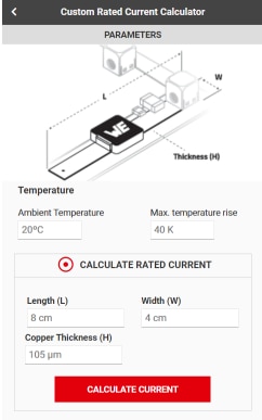
Figure 1: User interface of Rated Current Calculator with IEC62024-2 Class A 5 mm dimensions entered.
After the dimensions have been entered by the user, a Custom IR column is added to the parameter table (Figure 2) in addition to the temperature rise chart being updated to reflect the new conductor dimensions (Figure 3).
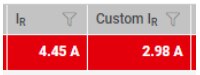
Figure 2: Datasheet Rated Current (left) and Custom Rated Current value (right) based upon dimensions entered in the user interface. Note how this value is different from that found in the datasheet. Therefore the PCB conductor is to narrow.
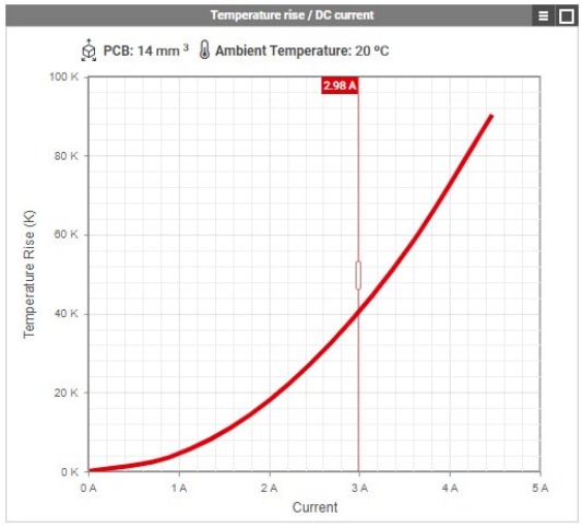
Figure 3: Temperature rise chart based upon dimensions entered into user interface.
These calculations use a numerical model which is based on and verified by measurements of components using different sized PCB traces. In this way the user can now view the rated current for Würth Elektronik power inductors on different sizes of copper conductor.The results can be used for comparisons with other power inductors or to estimate the rated current of a part when soldered to the application PCB. It should be noted that when used to estimate the rated current in the target application, it should be remembered that other components will contribute to the heat distribution in the PCB. These components such as ICs and capacitors could increase the temperature of the PCB or in the case of heat sinks lower the temperature of the PCB.
Consider the inductor WE-LHMI (74437346068) which has a performance rated current of 4.45 A (Figure 4). This is measured on an IEC 62024-2 IClass C PCB (Appendix). The graph displays the temperature rise as a result of the DC current for this component on the IClass A 5 mm, IClass C, and IClass D PCB. In addition the chart displays the output from the Rated Current Calculator in the REDEXPERT user interface available online as the data points. As can be seen, the calculated values are comparable to those gathered from component measurements.
This comparison demonstrates how the Rated Current Calculator determines the current with relative accuracy when compared to rated current measurements. It also demonstrates how the rated current of a part is highly reliant on the PCB conductor dimensions with the inductor being able to be operated at even higher currents than the rated current on the datasheet. Additionally, the comparison demonstrates that rated current are values to compare and guide in the selection of inductors before prototyping. It should be remembered that these are basic parameters, considering only DC currents with no additional heat generating parts on the PCB. In real conditions, AC losses and the thermal effects of surrounding components would also have to be considered, which account for most of the losses at higher switching frequencies. The actual temperature rises seen in the end applications will vary considerably dependent on the conditions.
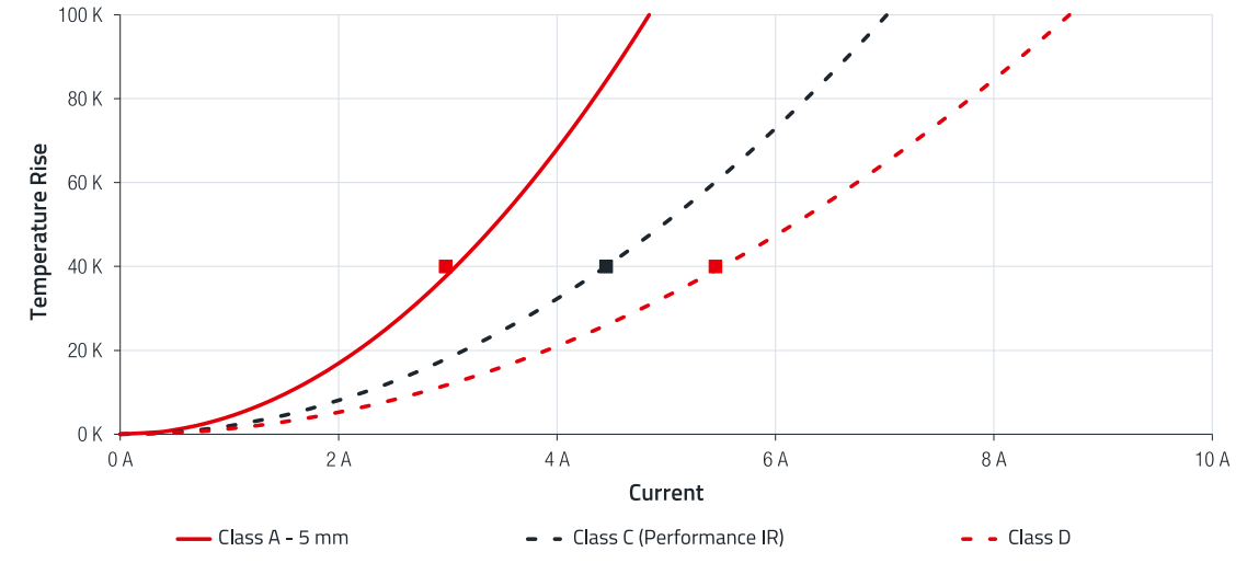
Figure 4: Self heating comparison of WE-LHMI 744 373 460 68 on different IEC 62024-2 PCBs and the calculated current for a 40K temperature rise using the Rated Current Calculator (data points).
4. CONCLUSION
Rated current values found on datasheets serve as a guide for the selection of power inductors. However, the temperature rise in power inductors can be influenced by the PCB conductor dimensions on which they are tested. These are not always comparable between all manufacturers giving a false sense of what the rated current values actually represent. Comparing similar parts from different manufactures on the same PCBs reveals that the thermal performance is almost analogous. To this end, Würth Elektronik has devised an online Rated Current Calculator which can determine the rated current of Würth Elektronik power inductors on a PCB using traces of the user’s choosing. This allows a rated current value to be estimated for the users end application or to compare the rated current values of inductors from other manufactures when the test PCB conductor dimensions are stated in the datasheet.
A. Appendix
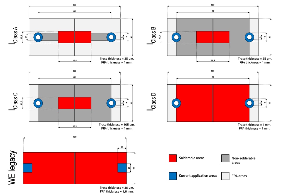
Figure 5: Diagram of PCBs used for rated current measurements in the IEC 62024-2
IMPORTANT NOTICE
The Application Note is based on our knowledge and experience of typical requirements concerning these areas. It serves as general guidance and should not be construed as a commitment for the suitability for customer applications by Würth Elektronik eiSos GmbH & Co. KG. The information in the Application Note is subject to change without notice. This document and parts thereof must not be reproduced or copied without written permission, and contents thereof must not be imparted to a third party nor be used for any unauthorized purpose. Würth Elektronik eiSos GmbH & Co. KG and its subsidiaries and affiliates (WE) are not liable for application assistance of any kind. Customers may use WE’s assistance and product recommendations for their applications and design. The responsibility for the applicability and use of WE Products in a particular customer design is always solely within the authority of the customer. Due to this fact it is up to the customer to evaluate and investigate, where appropriate, and decide whether the device with the specific product characteristics described in the product specification is valid and suitable for the respective customer application or not. The technical specifications are stated in the current data sheet of the products. Therefore the customers shall use the data sheets and are cautioned to verify that data sheets are current. The current data sheets can be downloaded at www.we-online.com. Customers shall strictly observe any product-specific notes, cautions and warnings. WE reserves the right to make corrections, modifications, enhancements, improvements, and other changes to its products and services. WE DOES NOT WARRANT OR REPRESENT THAT ANY LICENSE, EITHER EXPRESS OR IMPLIED, IS GRANTED UNDER ANY PATENT RIGHT, COPYRIGHT, MASK WORK RIGHT, OR OTHER INTELLECTUAL PROPERTY RIGHT RELATING TO ANY COMBINATION, MACHINE, OR PROCESS IN WHICH WE PRODUCTS OR SERVICES ARE USED. INFORMATION PUBLISHED BY WE REGARDING THIRD-PARTY PRODUCTS OR SERVICES DOES NOT CONSTITUTE A LICENSE FROM WE TO USE SUCH PRODUCTS OR SERVICES OR A WARRANTY OR ENDORSEMENT THEREOF. WE products are not authorized for use in safety-critical applications, or where a failure of the product is reasonably expected to cause severe personal injury or death. Moreover, WE products are neither designed nor intended for use in areas such as military, aerospace, aviation, nuclear control, submarine, transportation (automotive control, train control, ship control), transportation signal, disaster prevention, medical, public information network etc. Customers shall inform WE about the intent of such usage before design-in stage. In certain customer applications requiring a very high level of safety and in which the malfunction or failure of an electronic component could endanger human life or health, customers must ensure that they have all necessary expertise in the safety and regulatory ramifications of their applications. Customers acknowledge and agree that they are solely responsible for all legal, regulatory and safety-related requirements concerning their products and any use of WE products in such safety-critical applications, notwithstanding any applicationsrelated information or support that may be provided by WE. CUSTOMERS SHALL INDEMNIFY WE AGAINST ANY DAMAGES ARISING OUT OF THE USE OF WE PRODUCTS IN SUCH SAFETYCRITICAL APPLICATION.
DIRECT LINK
ANP138 | Custom Rated Current Calculator
USEFUL LINKS:
Application Notes : https://we-online.com/en/support/knowledge/application-notes
Services: https://we-online.com/en/products/components/service
Contact : https://we-online.com/en/support/contact
CONTACT INFORMATION
Würth Elektronik eiSos GmbH & Co. KG
Max-Eyth-Str. 1, 74638 Waldenburg, Germany
Tel.: +49 (0) 7942 / 945 – 0
Email: appnotes@we-online.de