EMC Basics: Chip Bead Ferrites & Reading Datasheets
Author: Dheeraj Jain, Technology Strategist; Jenna Cummins
In our last article, we explained the difference between common mode and differential noise and gave some solutions for managing common mode noise via common mode chokes. However, that still leaves a big question: what do you do about differential noise? In this post, we will explain chip bead ferrites and how they can be used to deal with differential noise.
What Are Chip Bead Ferrites?
A chip bead ferrite is a small, special type of lossy inductor compared to a typical low loss power inductor. It is used to remove unwanted noise at high frequencies on supply voltage lines, ground planes, and data signals.
Remember the law of conservation of energy, which states that energy can be neither created nor destroyed — it can only be converted. That’s exactly what a chip bead ferrite is doing in this application. It is transforming unwanted signal energy into thermal energy. In other words, it's converting the unwanted signal into heat.
In order to maximize the transforming effect, it’s important to choose the appropriate material with the best characteristics at the specific frequency of interest for attenuation. All of Würth Elektronik’s chip bead ferrites use nickel zinc (NiZn) for its high resistivity because the windings are embedded in the core, yet are formulated to be lossy in different frequencies ranges for maximum attenuation.
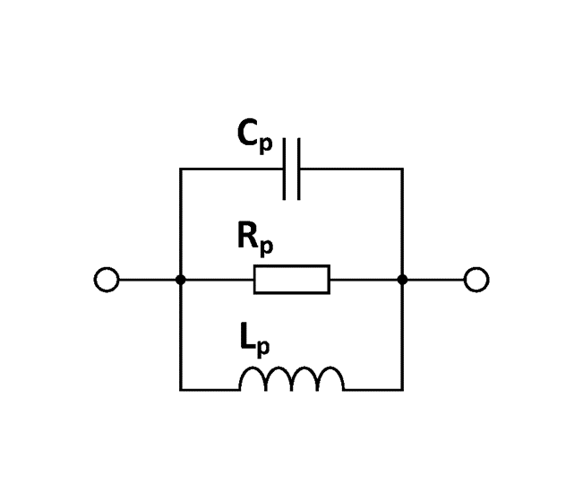
What you end up with at the end of the day is a frequency-dependent resistor. Figure 1 shows the parasitic elements of a chip bead ferrite. We need to always be cautious of these because a chip bead ferrite has inductance, capacitance, and resistance. We'll get into this further as we move along.

Figure 1. Parasitic elements of a chip bead ferrite.
An X-Ray View of a Chip Bead Ferrite
Figure 2 gives you an X-ray view of a chip bead ferrite. Keep in mind that the winding traces are not insulated and are embedded in the ferrite core.

Figure 2. X-Ray view of high-current and high-frequency chip bead ferrites.
As you can see, the winding of the high-current chip bead ferrite needs to be wider and thicker. That's because it has to handle higher current; therefore, they are often placed horizontally which results in higher winding self-capacitance.
The high-frequency chip bead ferrite needs to minimize winding self-capacitance, including capacitance to the terminals, so they have smaller surfaces and are placed vertically.
Inductive Reactance
Inductive reactance is the result of changing current flow which creates a magnetic field around a wire or coil which induces a counter voltage whose polarity is such that its current opposes the current that created it. This is based on Lenz's law, which states that the induced current must flow in the opposite direction of the primary current.

Figure 3. Elements of inductive reactance.
Inductive reactance (or XL) is a function of frequency and inductance. Inductance is governed primarily by the physical size, shape, core material and number of turns and remains constant below the self-resonant frequency. Therefore, the changing frequency changes the impedance.

How to Read a Chip Bead Ferrite Datasheet
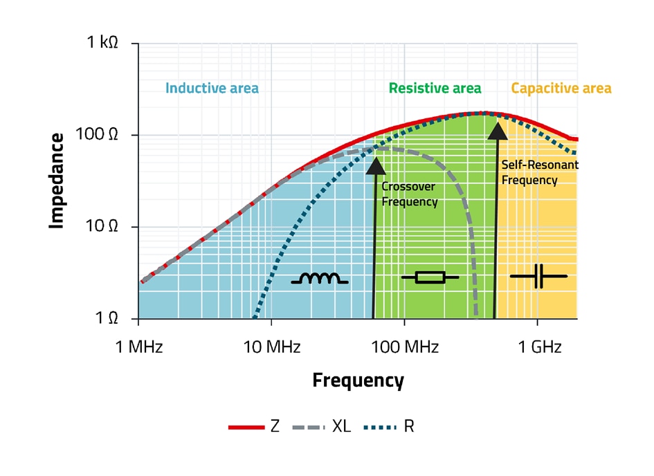
A chip bead ferrite has an inductance, resistance, and capacitance. Figure 4 shows regions where these characteristics have the most influence on impedance. They are highlighted in blue, green, and yellow, respectively on the impedance chart of a typical chip bead ferrite datasheet. Three curves are shown: Z is the impedance, XL is the inductive reactance, and the R is the resistive core losses of the part.

Figure 4. Example of a chip bead ferrite datasheet with parasitic element regions highlighted.
The crossover frequency is where the inductive reactance and the resistive core losses meet, shown on the chart where the gray and blue dotted lines cross. Below the crossover frequency, the inductive reactance is highest; in this range, the part is used as an inductor whose impedance opposes current. Above the crossover frequency, the resistive core losses are higher; at these frequencies, the part dissipates high frequency currents as heat – right up to the self-resonant frequency, or the SRF. The SRF is the point where there the inductance resonates with the parasitic capacitance resulting in very high impedance. Beyond this point the device becomes increasing capacitive.
The main purpose of the chip bead ferrite is to block unwanted AC noise. As the chip bead becomes more capacitive beyond the SRF, attenuation decreases.
Derating
As with any device, it is important to pay close attention to heat when choosing a chip bead ferrite. The chip bead ferrite is converting electrical energy to thermal energy and dissipating it as heat. That means there will be a temperature rise in the part, so you must also be aware of the ambient temperature in which the part will be operating.
Sometimes it will be necessary to derate the current because the core is very sensitive to temperature. For commercial-grade products, the core material we use has a maximum operating temperature of 125℃, which includes ambient temperature. Anything above 125℃ has the potential to approach the Curie temperature, where the permeability drops down to one, resulting no inductance. As a reminder, the Curie temperature is the point at which the material loses its magnetic permeability property.
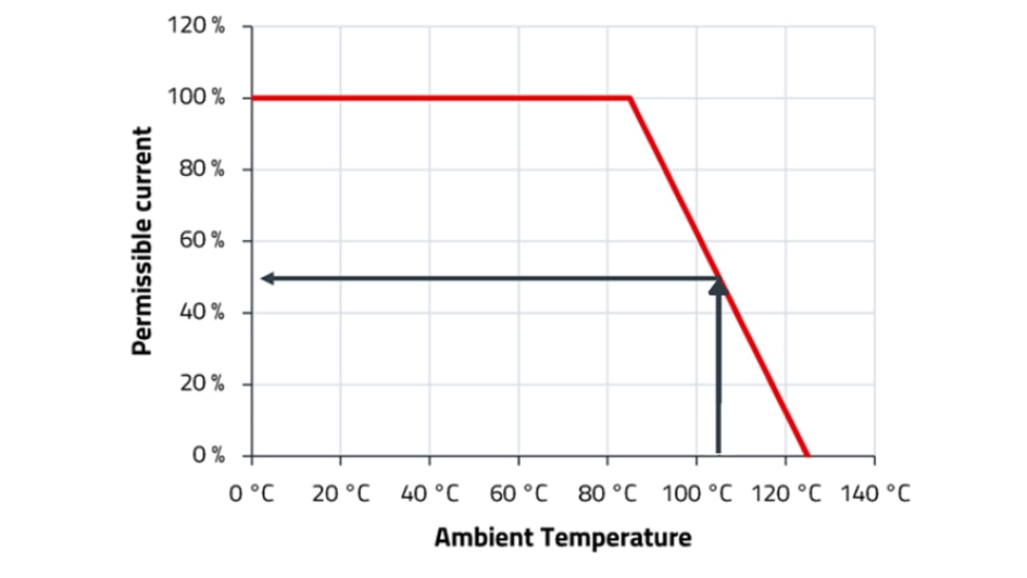
Here, we’ll look at a specific example of a product that has an ambient temperature above 85℃. We specify on our datasheets as 40° temperature rise above ambient when used at five amps (the rated current).

Figure 5. Temperature derating example for a chip bead ferrite.
Remember that since the part has an 85℃ ambient temperature, with a 40° K temperature rise, that would result in the maximum operating temperature of 125℃. In the case where the ambient temperature is 105℃, adding an additional 40° K temperature rise exceeds the maximum operating temperature. This means it is necessary to derate the part. Using the chart in Figure 5, find 105℃ along the x-axis and go up to the derating line and then horizontally to the derating percentage on the left vertical axis. We find that at 105℃ we must derate the current by 50%.
Therefore, at 2.5 amperes, there is a 20° K temperature rise, according to our datasheet. The results of the ambient temperature of 105℃ and a 20° K temperature rise puts you safely at 125℃ maximum operating temperature.
This example used some simple numbers. Going through these steps ensures the part will be under the maximum operating temperature and will function correctly.
Adding the Current
Würth Elektronik specifies chip bead ferrites with zero bias current, meaning we only show the impedance with no current flowing through the part. However, thanks to our REDEXPERT tool, we can also see how the components will perform with the current included.
Figure 6 below shows part number 7427927261 without current and with 0.10 amperes of current added. In the graphs, we see how the impedance drops and the self-resonant frequency shifts with current. This is important to note, as we want to ensure that the ferrite will be able to sufficiently attenuate the noise when current passes through it.


Figure 6. Chip bead ferrite 7427927261 shown with and without current. Without current, the peak impedance is near 255 MHz; with 0.10 A of current, the peak impedance is near 464 MHz.
By checking the performance of the ferrite with current included in REDEXPERT, it is easier to find a more accurate impedance value while designing.
How to Choose the Right Ferrite
Now we’re left with a big question: how do you choose the proper chip bead ferrite?
The answer is that it depends on various considerations, including your priorities and the design. Based on the application, it is important to take into consideration the frequency range of the noise, the source of the noise, the amount of attenuation needed, the environment, the electrical parameters of the circuit, and — as with everything else that you encounter — space and cost.
Ferrite Selection Example
Before getting into chip bead ferrite selection, the first step is to check what type of noise you are dealing with. To do this, you can conduct a test with a clamp-on ferrite; if you apply the clamp-on ferrite to the cable and the noise is not reduced, it is likely a differential noise problem.
Next, it’s time to determine the necessary impedance of the ferrite. For our example, we:
- require 20 dB of attenuation at the frequency of interest, say 125 MHz
- know ZIN, the power port source impedance is 10 Ω
- know ZOUT, the load impedance is 10 Ω

Figure 7. Example for chip bead ferrite selection.
From the chart, we see that in this example the minimum impedance needs to be at least 180 Ω at 125 MHz to have the desired 20 dB attenuation. This is based on the formula

Where
ZF = attenuation impedance
A = attenuation in dB
ZIN = source impedance
ZOUT = load impedance
One way to easily evaluate and compare different ferrite options is through Wurth Elektronik’s online tool REDEXPERT. REDEXPERT allows you to enter the details of your system and compare the performance of different components.
To find options matching the example, you would input these values:
- 20 dB attenuation
- Cut off frequency: 125 MHz
- ZIN: 10 Ω
- ZOUT :10 Ω
Then, you will be able to see the ferrites matching those requirements, as shown below. To further explore the REDEXPERT results from this example, you can check out the website here.

Figure 8. REDEXPERT ferrite selection.
By now, you have gained a solid overview of EMC, how it relates to chip bead ferrites, and how to read a datasheet. If you still have EMC questions, you can go back to our previous articles here.


Top Comments