Isolated MagI³C Power Module Masters the 24V Industry Bus
Selection Criteria and Voltage Ranges
Author: Timur Uludag / Editor: Gerhard Stelzer
In the industrial environment, 24 V bus systems are widely used to supply a wide range of field devices. What problems can arise during implementation and how can they be solved?
Every industry control circuit needs a supply voltage. However as the industry control circuit is only a small part in a larger electrical environment, a lot of specification parameters have to be considered to choose the adequate supply device. During the design in of a DC/DC converter, the ever-present questions from the designer are:
- What is the input voltage range?
- What is the output voltage (range)?
- How much power do I need?
What kind of isolated power module do we need?
The following applications are typical for an industrial environment such as bottling plants, rolling mills, conveyor belts and printing presses:
- Interface/Bus Isolation – RS232, RS485, CAN, Interbus, Profibus
- Isolation of Digital circuits
- Sourcing isolated amplifier, analog-to-digital converter
- Measurement and data acquisition
All these applications have one thing in common, which is that the input supply voltage is isolated from the bus voltage. But why should you galvanically isolate a supply from a bus or switching components in general? Galvanic isolation prevents faults that can propagate from the supply voltage into the bus and disturb its operation.
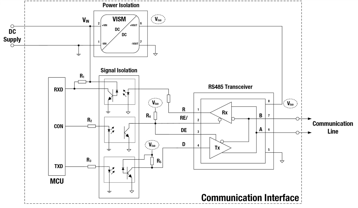
Figure 1 shows a typical application for an isolated power module. It shows the set-up for isolated RS485 communication with the essential functional units.

Figure 1. Typical set-up for an isolated RS485 communication with the essential functional units.
The following functional units are necessary to set up isolated communication:
The microcontroller unit (MCU) provides the data for the RS485 transceiver and receives data from it. The signal isolation unit implements galvanic isolation of the signals using optocouplers. Galvanic isolation of the grounds between the signal isolation unit and the transceiver unit is achieved with a power isolation unit - a DC/DC converter power module.
Wide voltage range
In terms of input voltage range, 8V to 42V has been set as the typical industry range for decades. This voltage range has been selected for two reasons. First, it is inspired from existing relevant standards such as IEC61131-2 for programmable logic controllers (PLC). Second, field experience with electrical supply and installation conditions confirmed and agreed with this voltage range. It should be noted that the most commonly used rail voltages of 12V and 24V can be covered with this classical voltage range. Typically, industrial applications are using 2:1 and 4:1 isolated converters to cover the wide input voltage range of 8V to 42V as shown in figure 2.
As an explanation to the terminology, the first number of a 2:1 or 4:1 converter indicates the multiplication factor. And this value is multiplied by a minimum input voltage value to get the maximum voltage range value. This means for a 2:1 converter with a minimum input voltage value of 4.5V, the input voltage ranges only from 4.5V to 9V. If another voltage range is needed, a different type of module needs to be chosen. But none of the commonly available 2:1 and 4:1 modules cover the industrial voltage range in total. The 5:1 SIP-8 module from Würth Elektronik covers with one type the complete industrial range of 8V to 42V. If we also take into account the adjustable output voltage (3.3V to 6V) of the SIP-8 module the added value is even more obvious. It can address common applications like CAN or RS485 for isolated converters with 1W, which need a supply voltage of 3.3V or 5V.

Figure 2. Industrial voltage ranges and how typical DC/DC converter types fit these.
To supply an application with 3.3V and 5V, two types of power modules are needed instead of one with an adjustable output voltage like the SIP-8.
The 5:1 SIP-8 with wide input/output voltage range reduces the type of different converters as well as the number of designs that have to be conceived, configured, tested, EMI conformity proven, and logistically handled.
This article series to be continued with “Wide voltage range – Input voltage limits”.

