Isolated MagI³C Power Module Mastering the 24V Industry Bus
Wide Voltage Range – Input Voltage Limits
Author: Timur Uludag / Editor: Gerhard Stelzer
In the industrial environment, 24 V bus systems are widely used to supply a wide range of field devices. Part 1 explained selection criteria for power modules and typical voltage ranges. Part 2 now elaborates on the issues with input voltage limits.
Initially it is helpful to have a common understanding of the structure of an industrial application, such as which voltages are present and why.
Industrial applications are known for long connecting lines between the separated parts of the application. Due to the spatial extensions the length of these connecting lines can be in the range of tens of meters.
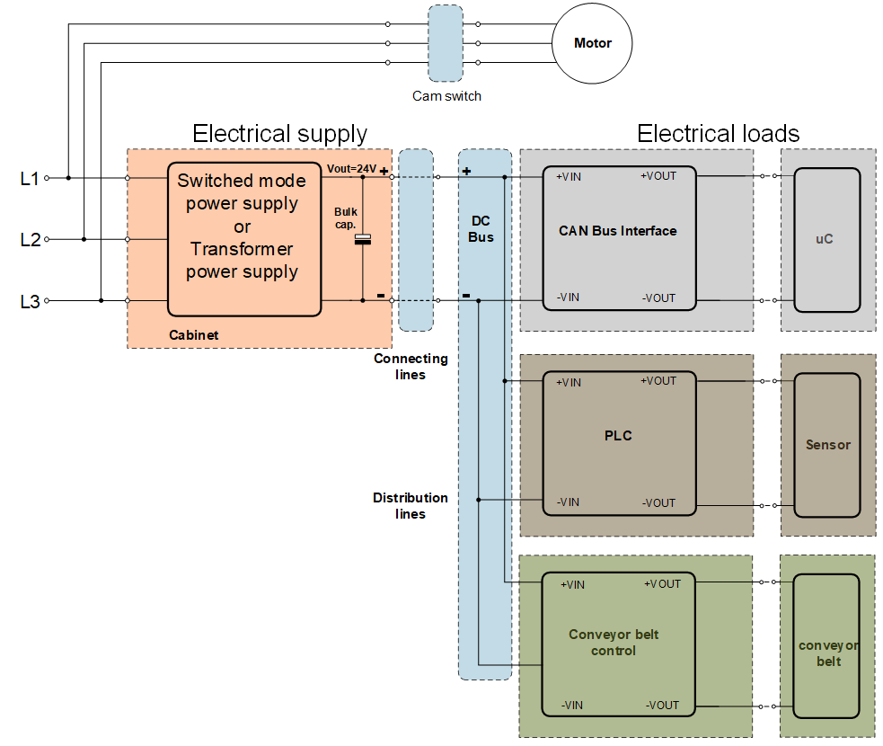
Figure 1 shows the basic structure of an industry plant. Nowadays, the electrical supply is realized through cabinets with switched mode power supplies or transformer power supplies. Transformer power supplies are still common for higher power supply. The separated parts of the applications are supplied through a DC bus. On site, every separated electrical load is connected via a sub distribution with 24V. It is easier to generate the 24V in a centralized cabinet and distribute the voltage through a DC bus than to distribute the hazardous 230Vac / 400Vac. This also reduces the number of separate power supplies.
Based on that structure there are three main influencing phenomena to the DC bus voltage:
- The voltage from the electrical supply
- Disturbances to the DC bus from running cables that are placed in parallel
- Voltage drops due to current flow
This article series is being continued with “Minimum input voltage – lower limit”.

Figure 1. Typical industrial set-up of power supplies.

