


If you are here to see how to add Ethernet / soundcard functionality to the Pi Zero, this is a part to be used in my automated amateur radio WSPR transceiver. Explanation of which can be found here: WSPRpi part 0: Introduction and what is WSPR? If you are not interested in how I intend to use it and just want to see how to add Ethernet or a soundcard to a Pi Zero, skip to the Design section.
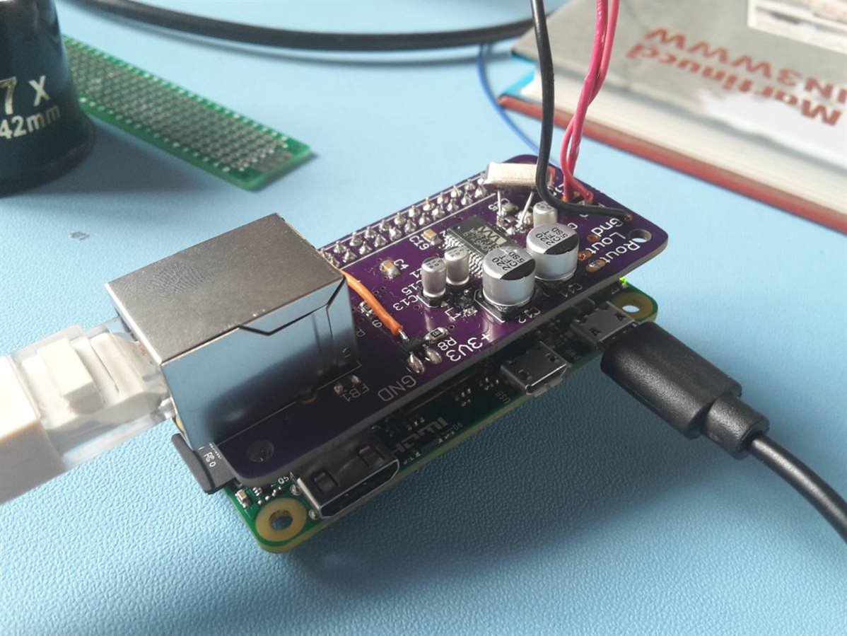
Finished result
WSPRpi
For people interested in the use in the WSPRpi project:
The two most important features for the Pi to be able to receive WSPR signals are an audio input and an network connection. I say network connection as the WSPRpi may be used on DXpeditions without Internet connection so will provide a web server showing the received stations. This is why the Ethernet connection was still useful, even with the Pi Zero W being released when I was waiting for the PCBs to be delivered as often a wired LAN is run between the operators laptops but no wireless connection is available. If a connection to the Internet is present, it will also upload the spots to the WSPR database automatically.
Design
This is based around two main ICs, the Wolfson / Cirrus Logic WM8731 audio codec and the Microchip ENC28J60 SPI to Ethernet adapter. Both of these parts were chosen as they had kernel drivers built in to the Raspbian distro, making using them relatively simple. There is little more to this design than the datasheet use circuit for both, put onto the same PCB. This produces the following schematic, I have attached the schematic as well:
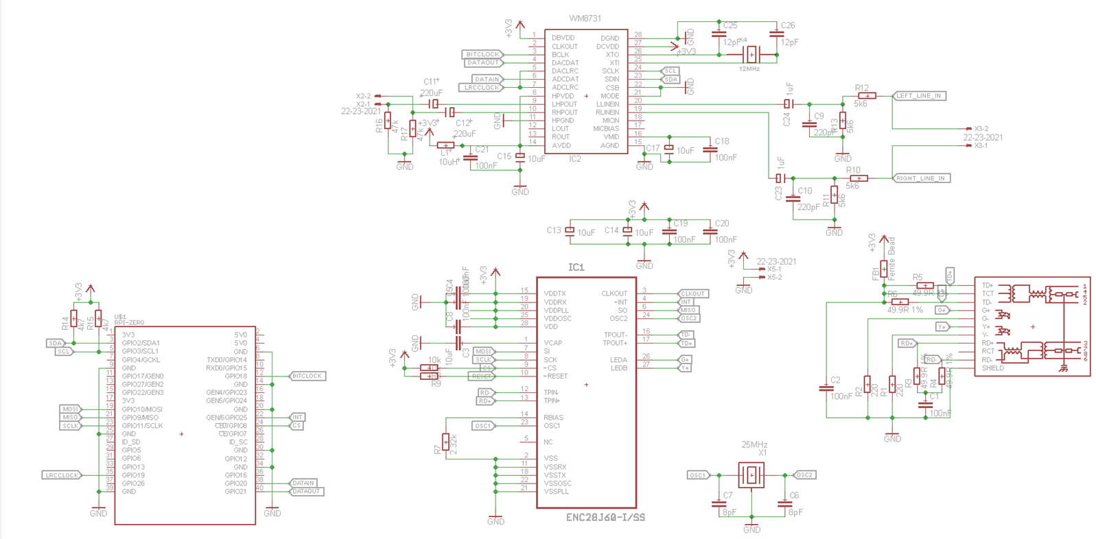
R14 and R15 are not needed. They were put there in case the I2C bus required the external pull-up resistors but it works fine without. Strictly, the audio output filter components (C11, C12. R16, R17) are also not required for the WSPRpi as it only needs audio input but I added footprints for them as everything else was already in place. It's also an easier way to test the functionality of the WM8731.
Layout
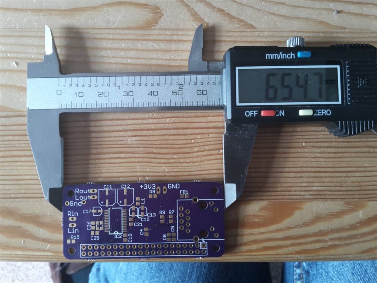
The PCB was laid out, mainly trying to fit all those parts in the small footprint of the Pi Zero and keeping all the high speed data buses away from each other.
This was achieved but does mean that fairly small parts are used (SSOP IC) and the crystals have pads only on the bottom, meaning soldering these with a soldering may be a bit of an endeavour. Luckily, I have an Atten hot air station which managed these no problem.
Construction
I assembled the Ethernet portion of the board first as I wanted to use SSH to access the Pi. I don't have much space and having a second monitor around for longer than necessary would be a pain.
I have highlighted these on the BOM (attached also)
Preliminary Testing
I began by connecting the board (no Pi connected) to a 3.3V supply and it drew approximately 120mA which matched with a cheap Chinese breakout board for the same chip. If an Ethernet cable (connected to a router) is plugged in, the orange LED on the Ethernet connector should turn on and the green LED should flash, indicating network activity.
Mistake No. 1
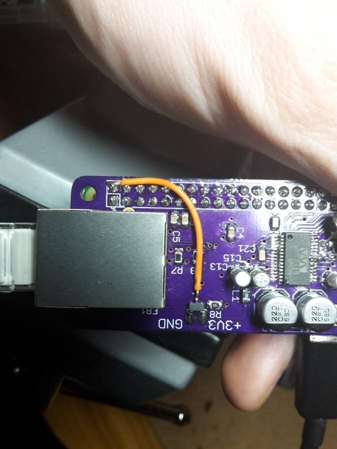
I did not get any flashing LEDs, and got errors in the next step, Setup on the Pi, with a non responsive device. Due to the simplicity of the connections between the Pi and the ENC28J60, this pointed at bad soldering, incorrect power supply, wrong pinout or something wrong with the crystal. I double checked my soldering with decent magnification and it looked fine.The Eagle footprint was download from Farnell / element14 so was reasonably confident with that. Power supply was straight from my bench PSU so again unlikely. Probing with an oscilloscope showed both pins at about 1.1V DC. It turned out I had got my footprint for the crystal wrong, shorted both of the oscillator pins of the IC to the can and connected both ends of the crystal to ground. Oops!. Minor surgery later and this was fixed.
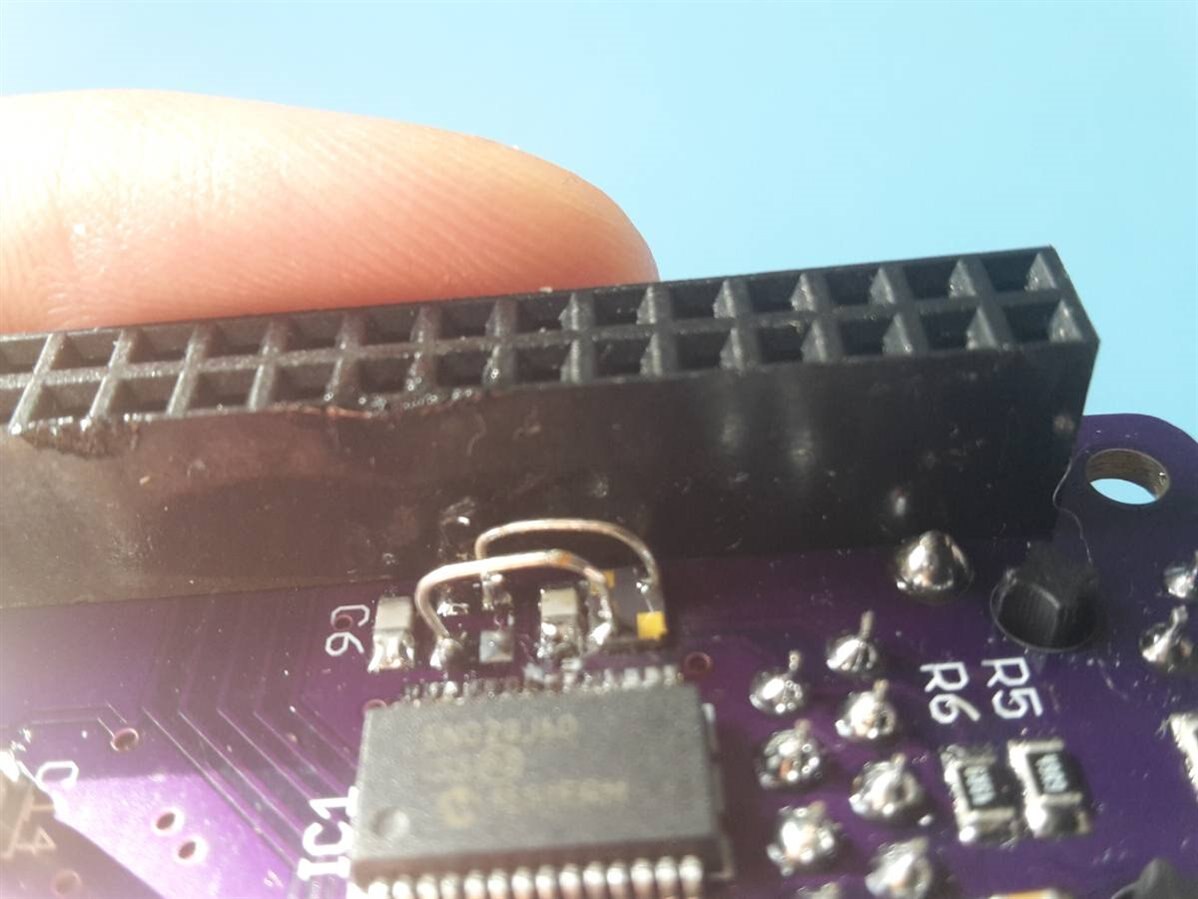
Bodge on the crystal. Please excuse the slightly melted pin header due to trying to fix this! This is a prototype board which is not quite right mechanically (connector locations and such) for the WSPR so I corrected this for v1.1 which will hopefully be the final version in the WSPRpi.
Setup on the Pi
I advise not plugging the Ethernet cable in until I mention to as I discovered some interesting things with how the driver handles addressing, explained in Set constant MAC address.
As the drivers for this are already part of the Raspbian distro, enabling these is very easy, at least for Raspbian users, I'm not sure about other distros. Once the board was connected to the Pi.
Going from a fresh install of Rapsbian (I used Jessie Lite, March 2017) I used the Lite version as I did not need a desktop for WSPRpi but the full version will also be fine.
Once logged in (as usual username pi, password raspberry)
Edit config.txt:
sudo nano /boot/config.txt
Add the following to the bottom:
dtoverlay=enc28j60
Reboot:
sudo reboot
Done!
Once logged back in, run dmesg
dmesg
This will give you one of two possible results:
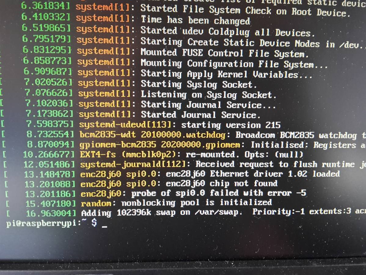
Option 1: This is not good, the line at 13.148478 shows the driver was loaded fine so editing config.txt was fine but the line at 13.201186 shows that it couldn't find the 28J60.
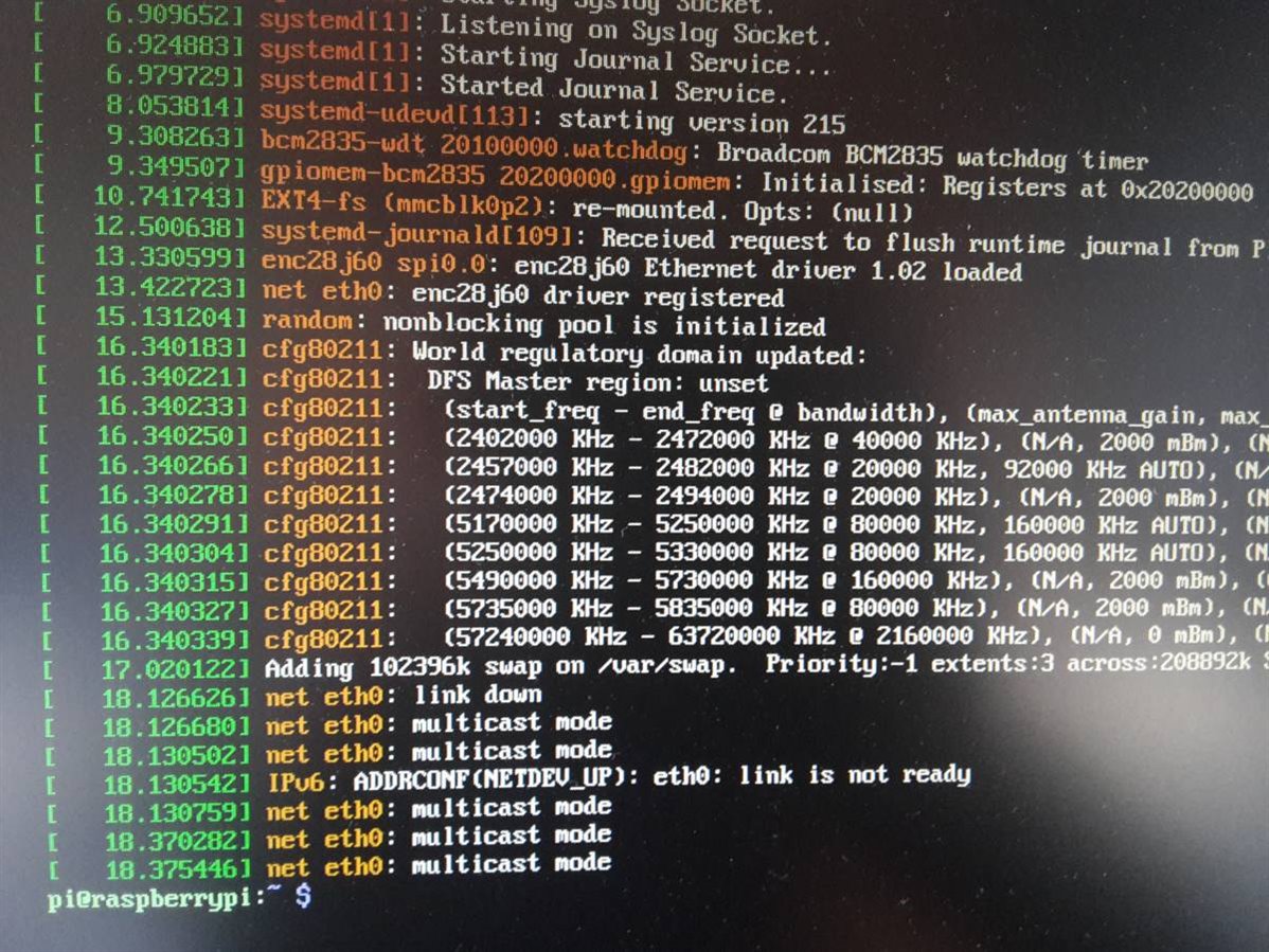
Option 2: Success, as shown by the line at 13.422723. eth0 is showing as link not ready as I didn't have an Ethernet Cable plugged in.
Set constant MAC address
Initially I ran the Pi with a static IP so didn't have this problem, switching back to DHCP (router assigns the IP address) led to problems. A MAC address should uniquely identify the hardware and be the same after reboot. In Raspberry Pis with onboard Ethernet, this is calculated as a function of serial number and a series of MAC address that appear to be linked to Rapsberry Pi ensuring each is unique and doesn't change due to the serial number being hard coded. The kernel module for the 28J60 Ethernet controller instead randomly generates the MAC address on startup and on every reboot which will make most DHCP routers unhappy as they assign a different IP address to devices with different MAC addresses.
This was being a pain as my Pi didn't have a constant IP address to allow me to SSH in so this next step assigns a constant MAC address to the Pi.
Thank to Richard from http://raspi.tv/2015/ethernet-on-pi-zero-how-to-put-an-ethernet-port-on-your-pi
1) Create the file /lib/systemd/system/setmac.service
sudo nano /lib/systemd/system/setmac.service
2) Add the following contents:
[Unit]
Description=DSet the MAC address for the ENC28J60 enet adapter at eth0
Wants=network-pre.target
Before=network-pre.target
BindsTo=sys-subsystem-net-devices-eth0.device
After=sys-subsystem-net-devices-eth0.device

[Service]
Type=oneshot
ExecStart=/sbin/ip link set dev eth0 address 00:00:00:00:00:00
ExecStart=/sbin/ip link set dev eth0 up

[Install]
WantedBy=multi-user.target
Change the MAC address (shown above 00:00:00:00:00:00) to whatever. I recommend B8:27:EB:xx:xx:xx (x is 0-9 or A-F e.g. B8:27:EB:12:34:5A) as this prefix appears to be assigned to Raspberry Pis. At least, all of my Pis had this MAC address and it identified in Advanced IP Scanner as manufactured by the Raspberry Pi Foundation and appeared blank when another prefix was used.
3) Exit the editor (Ctrl-X, y, Enter)
4) Set File permissions
sudo chmod 644 /lib/systemd/system/setmac.service
5) Execute the following two commands to enable the service
sudo systemctl daemon-reload
sudo systemctl enable setmac.service
6) Reboot
sudo reboot
7) Check that this has been saved
ifconfig
Hopefully you will see the following where the address circled in blue is the MAC address you specified:
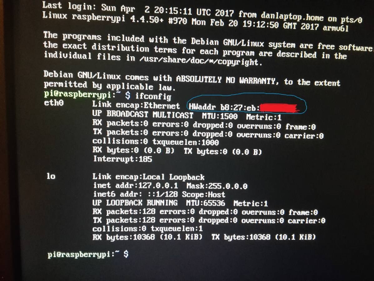
Now the Pi can be plugged into your router where it will be assigned an IP address which should be constant after reboot. I recommend testing it is connected to the Internet by seeing it can access a website e.g.:
ping google.com
I then went to speedtest.net and it measured download speeds of 5Mbps and 2Mbps upload, not bad!
Change Hostname (optional)
As this Pi would also be running a webserver, I went into raspi-config
sudo raspi-config
and changed the hostname (Option 2) to WSPRpi so I could access it later. I also updated Raspbian, to prevent issues installing anything in the future
sudo apt-get update
If you are following the WSPRpi project, please note this down as it will the web address of the server to view the received spots
Soundcard
All other components were then soldered onto the PCB.
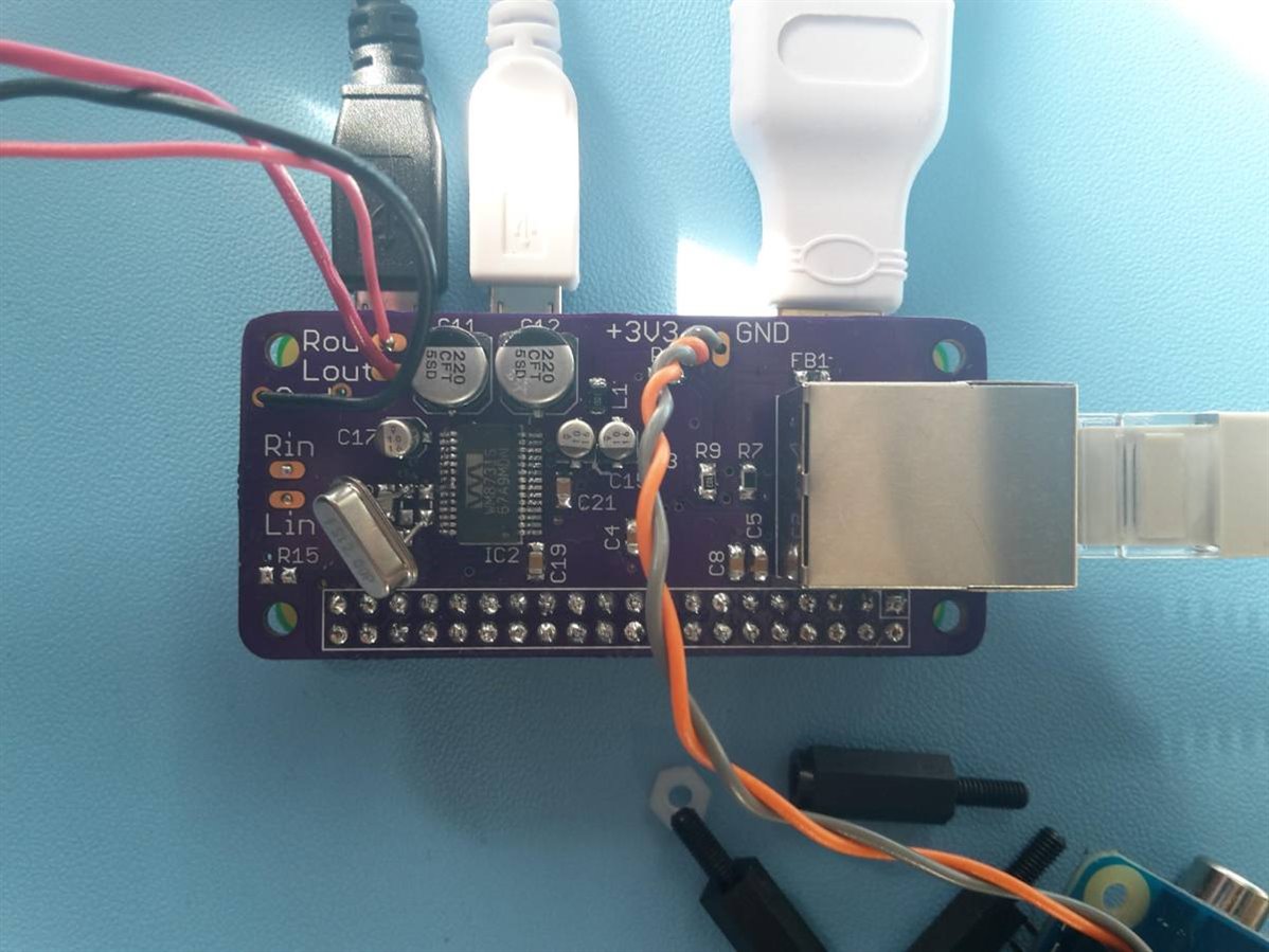
I know two pins on the IC are shorted, this is intentional (see Mistake 2)
Setup on the Pi
Again go into config.txt
sudo nano /boot/config.txt
Find the line that says
dtparam=audio=on
Comment it out as it interferes with the I2S bus used to talk to the audio coded we've added
#dtparam=audio=on
and add the following:
dtoverlay=audioinjector-wm8731-audio
Reboot
sudo reboot
Run dmesg to check on the state of the audio driver
dmesg
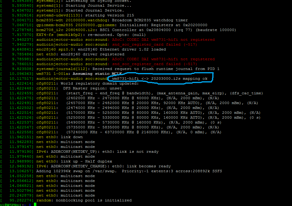
The two errors (in red text) are fine. The important line (circled in blue) is the one that says:
audioinjector-audio soc:sound: wm8731-hifi <-> 20203000.i2s mapping ok
This means everything is fine.
Mistake Number 2
Again I didn't get this working first time. Once again, device not responding which produces an output in dmesg which look like:
[ 5.710350] audioinjector-audio soc:sound: ASoC: CODEC DAI wm8731-hifi not registered
[ 5.710381] audioinjector-audio soc:sound: snd_soc_register_card failed (-517)
[ 5.746090] EXT4-fs (mmcblk0p7): re-mounted. Opts: (null)
[ 5.847273] audioinjector-audio soc:sound: ASoC: CODEC DAI wm8731-hifi not registered
[ 5.847304] audioinjector-audio soc:sound: snd_soc_register_card failed (-517)
[ 5.855053] wm8731 1-001a: Assuming static MCLK
[ 5.855425] wm8731 1-001a: Failed to issue reset: -5
[ 5.855535] wm8731: probe of 1-001a failed with error -5
[ 5.857826] usbcore: registered new interface driver brcmfmac
[ 5.858302] audioinjector-audio soc:sound: ASoC: CODEC DAI wm8731-hifi not registered
[ 5.858312] audioinjector-audio soc:sound: snd_soc_register_card failed (-517)
Again, the connections were very simple so: soldering, power supply, footprint or crystal.
Soldering: Checked with magnifying glass. It was fine.
Power supply: Fine
Crystal: Fine
Footprint: Turns out I had accidentally deleted a traced and left the mode pin floating. It needed to be shorted to ground to set the input to be I2C for the configuration instead of the default three wire protocol. One of the pins next to it (CSB) was grounded so I manually shorted these. This was surprisingly difficult on SSOP to selectively short just two pins! This has also been corrected for the version 1.1 PCBs.
Setup on Pi (continued)
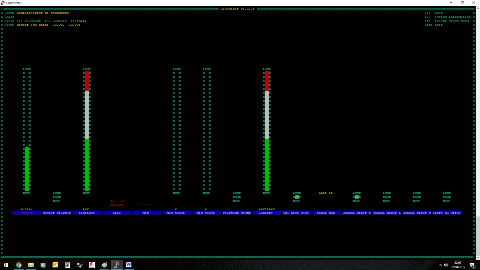
The sound card by default doesn't use the inputs and outputs that I used. To edit the open the mixer
alsamixer

The layout does look slightly different on the Pi, I'm doing this over SSH so the graphics are slightly different but it's functionally the same.
Press F5 to see all options then use the arrow keys to navigate to the "Line" option (4th one across) and press Space so it shows L R Capture. Navigate to the "Output Mixer HiFi" option and press "m". It should now be highlighted in green.
It should now look like the image below albeit with minor graphical differences if you are doing this directly on the Pi.
Final Testing
To test the sound output, I decided a bit of Internet radio would be a nice way to test both components of this build.
I plugged in a cheap pair of headphones into the Left and Right outputs. I didn't have room on the PCB for a proper socket so soldered one on wires to the board.
First I installed mplayer (This took a while)
sudo apt-get install mplayer
Then I used:
mplayer -playlist http://media-ice.musicradio.com/HeartYorkshireMP3.m3u
and the sound of Aerosmith indicated success!
I then added the above to the end of /etc/profile to have the Pi autostart streaming from Heart on power-up and used it as an Internet radio for a few days as it was very comfortable to listen to driving a 16 Ohm speaker.
Modifications
Once I was happy that the board worked, I soldered a 3.3V regulator and supplied it from the Pi's 5V output (GPIO pin 2) for convenience. This will not be needed in the final WSPRpi where I intend to have a motherboard all these sub-boards will plug into to supply power, it's just for testing.
Feedback
If you do build this / have feedback, it would be interesting to hear your thoughts, either as a comment here or on Twitter @m0wut.
Thanks and 73 (amateur radio speak for best wishes)
Dan M0WUT
 | |
| BOM.xlsx | |
Top Comments