



element14 Community
element14 Community
    Register Log In
  • Site
  • Search
  • Log In Register
  • Community Hub
    Community Hub
    • What's New on element14
    • Feedback and Support
    • Benefits of Membership
    • Personal Blogs
    • Members Area
    • Achievement Levels
  • Learn
    Learn
    • Ask an Expert
    • eBooks
    • element14 presents
    • Learning Center
    • Tech Spotlight
    • STEM Academy
    • Webinars, Training and Events
    • Learning Groups
  • Technologies
    Technologies
    • 3D Printing
    • FPGA
    • Industrial Automation
    • Internet of Things
    • Power & Energy
    • Sensors
    • Technology Groups
  • Challenges & Projects
    Challenges & Projects
    • Design Challenges
    • element14 presents Projects
    • Project14
    • Arduino Projects
    • Raspberry Pi Projects
    • Project Groups
  • Products
    Products
    • Arduino
    • Avnet & Tria Boards Community
    • Dev Tools
    • Manufacturers
    • Multicomp Pro
    • Product Groups
    • Raspberry Pi
    • RoadTests & Reviews
  • About Us
    About the element14 Community
  • Store
    Store
    • Visit Your Store
    • Choose another store...
      • Europe
      •  Austria (German)
      •  Belgium (Dutch, French)
      •  Bulgaria (Bulgarian)
      •  Czech Republic (Czech)
      •  Denmark (Danish)
      •  Estonia (Estonian)
      •  Finland (Finnish)
      •  France (French)
      •  Germany (German)
      •  Hungary (Hungarian)
      •  Ireland
      •  Israel
      •  Italy (Italian)
      •  Latvia (Latvian)
      •  
      •  Lithuania (Lithuanian)
      •  Netherlands (Dutch)
      •  Norway (Norwegian)
      •  Poland (Polish)
      •  Portugal (Portuguese)
      •  Romania (Romanian)
      •  Russia (Russian)
      •  Slovakia (Slovak)
      •  Slovenia (Slovenian)
      •  Spain (Spanish)
      •  Sweden (Swedish)
      •  Switzerland(German, French)
      •  Turkey (Turkish)
      •  United Kingdom
      • Asia Pacific
      •  Australia
      •  China
      •  Hong Kong
      •  India
      •  Japan
      •  Korea (Korean)
      •  Malaysia
      •  New Zealand
      •  Philippines
      •  Singapore
      •  Taiwan
      •  Thailand (Thai)
      •  Vietnam
      • Americas
      •  Brazil (Portuguese)
      •  Canada
      •  Mexico (Spanish)
      •  United States
      Can't find the country/region you're looking for? Visit our export site or find a local distributor.
  • Translate
  • Profile
  • Settings
Raspberry Pi
  • Products
  • More
Raspberry Pi
Blog External Antenna for Raspberry Pi 4
  • Blog
  • Forum
  • Documents
  • Quiz
  • Events
  • Polls
  • Files
  • Members
  • Mentions
  • Sub-Groups
  • Tags
  • More
  • Cancel
  • New
Join Raspberry Pi to participate - click to join for free!
Featured Articles
Announcing Pi
Technical Specifications
Raspberry Pi FAQs
Win a Pi
GPIO Pinout
Raspberry Pi Wishlist
Comparison Chart
Quiz
  • Share
  • More
  • Cancel
Group Actions
  • Group RSS
  • More
  • Cancel
Engagement
  • Author Author: aswinvenu
  • Date Created: 22 Sep 2024 2:56 PM Date Created
  • Views 23991 views
  • Likes 10 likes
  • Comments 13 comments
Related
Recommended
  • raspberry pi 4

External Antenna for Raspberry Pi 4

aswinvenu
aswinvenu
22 Sep 2024

Introduction

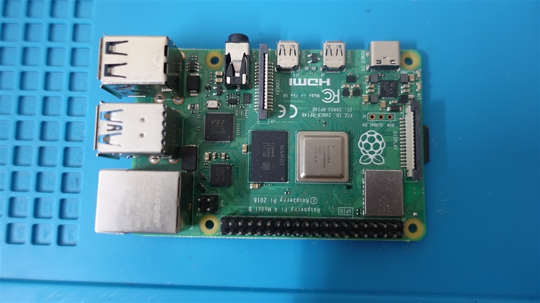
     For one of the Raspberry Pi projects I have been working on had this specific requirement for an external antenna. The entire Raspberry Pi 4 needs to be placed inside a metal box. So external antenna was the only option left for me to make the Bluetooth and WiFi to work. I had two choices, One to use the compute module 4 and use the IO board or use a regular RPi and somehow add a UFL/IPEX Connector to the PCB. Considering the cost and availability I preferred to try the second option.
image

    On a closer inspection of the WiFi/BLE Module area, We can see a small provision where a UFL/IPEX Connector can fit. Ofcourse there are no expose pads for an UFL/IPEX connector. We need to create one ( Atleast the ground pads ).

imageimage

Step 1

  Remove the solder mask and prepare a nice and clean exposed copper pad for soldering the UFL/IPEX connector.

image

Step 2

    Cut the trace which goes to the on PCB Antenna and solder a 0201 0E resistor like shown below. 

image

Step 3

   Remove the capacitors used in the PCB Antenna.

image

image

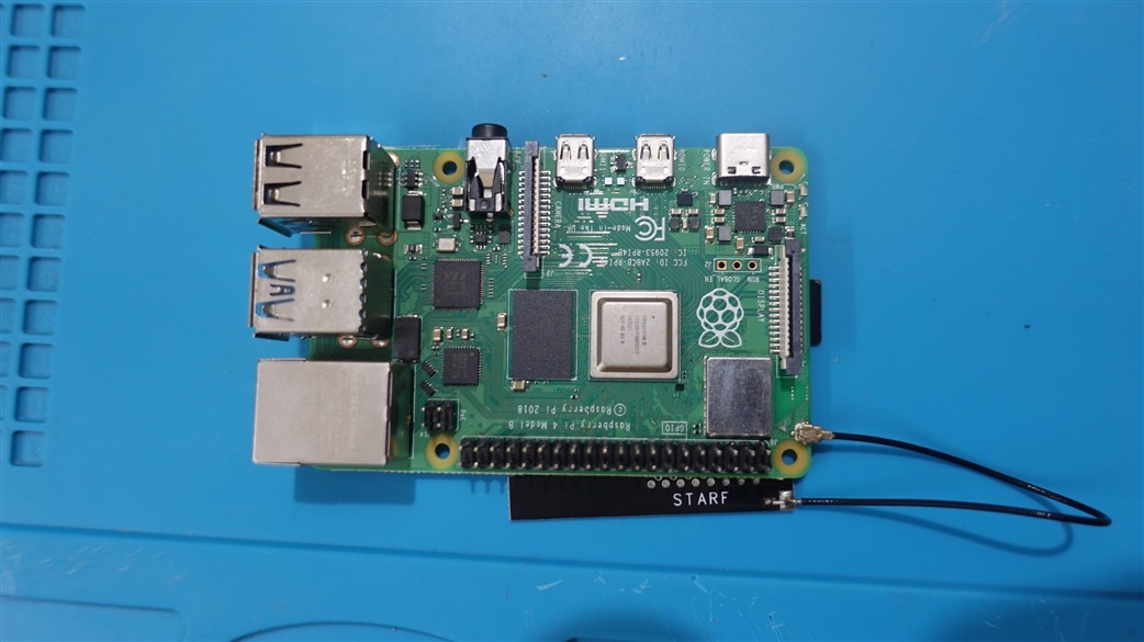
Done! I connected an IPEX 4dB antenna to the my RPi 4 for a quick test.
image

Result

Everything works fine and I am getting roughly 4- 5dB difference compared to the stock PCB antenna.

image

My router was atleast 5-6 meters away from the RPi and there was a wall separation.

  • Sign in to reply

Top Comments

  • shabaz
    shabaz over 1 year ago in reply to aswinvenu +2
    That's slightly different, that's unwanted emissions (but also relevant for products for sure). Every country has a regulatory body for wireless, e.g. in the USA it is FCC, and in the UK it is Ofcom (those…
  • shabaz
    shabaz over 1 year ago in reply to aswinvenu

    I believe the standards define radiated power (i.e. not transmitter power) for WiFi, so for that reason often the antenna is either not replaceable, or has no RF connector, or uses a funny connector (RP-SMA, etc). Regarding the 'quick way to damage the board', there's perhaps just a small risk of that at the power levels involved, but I wasn't thinking of that; that comment was in regards to the next bit of the sentence, i.e. the 0201 resistor. Lots of people have huge soldering irons, and may end up just lifting pads due to heat, and losing the 0201 resistor inside the solder blob anyway!

    • Cancel
    • Vote Up 0 Vote Down
    • Sign in to reply
    • More
    • Cancel
  • aswinvenu
    aswinvenu over 1 year ago in reply to shabaz

    I thought of using  CM4IO Board and  CM4. But unfortunately, I couldn't fit everything inside the Metal Box ( Junction Box ). Now the other options I have is to use some waveshare boards. Which I am still exploring. The only advantage I can see using the regular RPi is my procurement becomes whole lot easier. But still exploring.


    "i, it might be worth pointing out that there is a risk of exceeding the allowed power level (which is why they have the solder resist on that connector), and it's a quick way to damage the board too"

    You meant the TX Power ?

    • Cancel
    • Vote Up 0 Vote Down
    • Sign in to reply
    • More
    • Cancel
  • shabaz
    shabaz over 1 year ago

    Hi!

    I guess you had little choice since the box was metal. It could also be worth using a Pi Compute Module instead since that comes with the RF connector already fitted. There are "baseboards" that the compute modules can plug on top of, to give the same form factor of the original Pi.

    For anyone thinking they want to do this on a Pi, it might be worth pointing out that there is a risk of exceeding the allowed power level (which is why they have the solder resist on that connector), and it's a quick way to damage the board too, since an 0201 resistor is not normal : ) That took some skill to do, not easy the first time around.

    Anyway, good work, glad it worked out for your need.

    • Cancel
    • Vote Up 0 Vote Down
    • Sign in to reply
    • More
    • Cancel
<
element14 Community

element14 is the first online community specifically for engineers. Connect with your peers and get expert answers to your questions.

  • Members
  • Learn
  • Technologies
  • Challenges & Projects
  • Products
  • Store
  • About Us
  • Feedback & Support
  • FAQs
  • Terms of Use
  • Privacy Policy
  • Legal and Copyright Notices
  • Sitemap
  • Cookies

An Avnet Company © 2026 Premier Farnell Limited. All Rights Reserved.

Premier Farnell Ltd, registered in England and Wales (no 00876412), registered office: Farnell House, Forge Lane, Leeds LS12 2NE.

Follow element14

  • X
  • Facebook
  • linkedin
  • YouTube