element14 Community
element14 Community
    Register Log In
  • Site
  • Search
  • Log In Register
  • Community Hub
    Community Hub
    • What's New on element14
    • Feedback and Support
    • Benefits of Membership
    • Personal Blogs
    • Members Area
    • Achievement Levels
  • Learn
    Learn
    • Ask an Expert
    • eBooks
    • element14 presents
    • Learning Center
    • Tech Spotlight
    • STEM Academy
    • Webinars, Training and Events
    • Learning Groups
  • Technologies
    Technologies
    • 3D Printing
    • FPGA
    • Industrial Automation
    • Internet of Things
    • Power & Energy
    • Sensors
    • Technology Groups
  • Challenges & Projects
    Challenges & Projects
    • Design Challenges
    • element14 presents Projects
    • Project14
    • Arduino Projects
    • Raspberry Pi Projects
    • Project Groups
  • Products
    Products
    • Arduino
    • Avnet Boards Community
    • Dev Tools
    • Manufacturers
    • Multicomp Pro
    • Product Groups
    • Raspberry Pi
    • RoadTests & Reviews
  • Store
    Store
    • Visit Your Store
    • Choose another store...
      • Europe
      •  Austria (German)
      •  Belgium (Dutch, French)
      •  Bulgaria (Bulgarian)
      •  Czech Republic (Czech)
      •  Denmark (Danish)
      •  Estonia (Estonian)
      •  Finland (Finnish)
      •  France (French)
      •  Germany (German)
      •  Hungary (Hungarian)
      •  Ireland
      •  Israel
      •  Italy (Italian)
      •  Latvia (Latvian)
      •  
      •  Lithuania (Lithuanian)
      •  Netherlands (Dutch)
      •  Norway (Norwegian)
      •  Poland (Polish)
      •  Portugal (Portuguese)
      •  Romania (Romanian)
      •  Russia (Russian)
      •  Slovakia (Slovak)
      •  Slovenia (Slovenian)
      •  Spain (Spanish)
      •  Sweden (Swedish)
      •  Switzerland(German, French)
      •  Turkey (Turkish)
      •  United Kingdom
      • Asia Pacific
      •  Australia
      •  China
      •  Hong Kong
      •  India
      •  Korea (Korean)
      •  Malaysia
      •  New Zealand
      •  Philippines
      •  Singapore
      •  Taiwan
      •  Thailand (Thai)
      • Americas
      •  Brazil (Portuguese)
      •  Canada
      •  Mexico (Spanish)
      •  United States
      Can't find the country/region you're looking for? Visit our export site or find a local distributor.
  • Translate
  • Profile
  • Settings
Raspberry Pi
  • Products
  • More
Raspberry Pi
Blog External Antenna for Raspberry Pi 4
  • Blog
  • Forum
  • Documents
  • Quiz
  • Events
  • Polls
  • Files
  • Members
  • Mentions
  • Sub-Groups
  • Tags
  • More
  • Cancel
  • New
Join Raspberry Pi to participate - click to join for free!
Featured Articles
Announcing Pi
Technical Specifications
Raspberry Pi FAQs
Win a Pi
GPIO Pinout
Raspberry Pi Wishlist
Comparison Chart
Quiz
  • Share
  • More
  • Cancel
Group Actions
  • Group RSS
  • More
  • Cancel
Engagement
  • Author Author: aswinvenu
  • Date Created: 22 Sep 2024 2:56 PM Date Created
  • Views 8420 views
  • Likes 10 likes
  • Comments 13 comments
Related
Recommended
  • raspberry pi 4

External Antenna for Raspberry Pi 4

aswinvenu
aswinvenu
22 Sep 2024

Introduction

     For one of the Raspberry Pi projects I have been working on had this specific requirement for an external antenna. The entire Raspberry Pi 4 needs to be placed inside a metal box. So external antenna was the only option left for me to make the Bluetooth and WiFi to work. I had two choices, One to use the compute module 4 and use the IO board or use a regular RPi and somehow add a UFL/IPEX Connector to the PCB. Considering the cost and availability I preferred to try the second option.

image

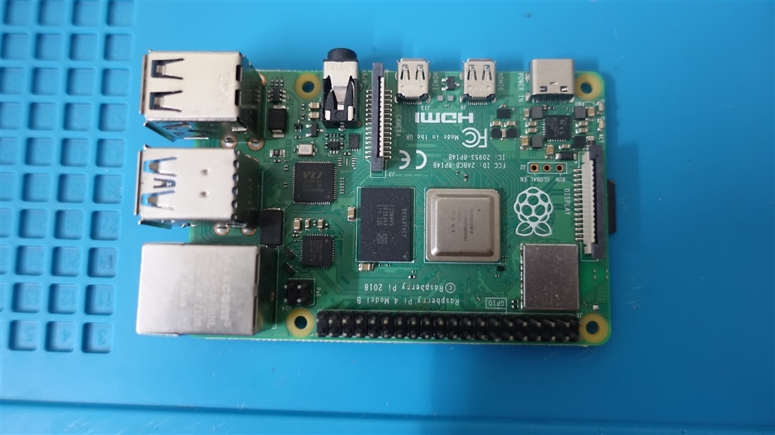
    On a closer inspection of the WiFi/BLE Module area, We can see a small provision where a UFL/IPEX Connector can fit. Ofcourse there are no expose pads for an UFL/IPEX connector. We need to create one ( Atleast the ground pads ).

imageimage

Step 1

  Remove the solder mask and prepare a nice and clean exposed copper pad for soldering the UFL/IPEX connector.

image

Step 2

    Cut the trace which goes to the on PCB Antenna and solder a 0201 0E resistor like shown below. 

image

Step 3

   Remove the capacitors used in the PCB Antenna.

image

image

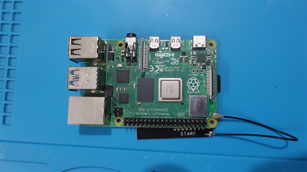
Done! I connected an IPEX 4dB antenna to the my RPi 4 for a quick test.

image

Result

Everything works fine and I am getting roughly 4- 5dB difference compared to the stock PCB antenna.

image

My router was atleast 5-6 meters away from the RPi and there was a wall separation.

  • Sign in to reply

Top Comments

  • shabaz
    shabaz 9 months ago in reply to aswinvenu +2
    That's slightly different, that's unwanted emissions (but also relevant for products for sure). Every country has a regulatory body for wireless, e.g. in the USA it is FCC, and in the UK it is Ofcom (those…
  • zip00
    zip00 4 months ago

    What about mounting a diversity between the two traces? Is that possible?

    • Cancel
    • Vote Up 0 Vote Down
    • Sign in to reply
    • More
    • Cancel
  • zip00
    zip00 4 months ago in reply to aswinvenu

    So I will solder a mini piece of wire instead resistor, cut the trace and leave the cups (to leave the possibility of reversibility). Can you confirm that this mod will increase bluetooth signal too?

    • Cancel
    • Vote Up 0 Vote Down
    • Sign in to reply
    • More
    • Cancel
  • aswinvenu
    aswinvenu 4 months ago in reply to zip00

    Out of the box RPi doesn't have a continuous trace running from the antenna output to the IPEX connector. There is a provision for an 0201 0E resistor.

    This is a common technique used in the PCBs if you want to select between external antenna or a PCB/Trace antenna. (ESP32 WROVER boards for example )

    Answering your second question, You don't necessarily need to remove the caps after cutting the trace. I don't have any experimental data supporting one is better than the other. But I would like it to be removed because those 4 caps are part of the PCB antenna structure.

    • Cancel
    • Vote Up 0 Vote Down
    • Sign in to reply
    • More
    • Cancel
  • zip00
    zip00 4 months ago

    Hi, can you tell the pourpose to solder a 0ohm resistor between the traces and remove the capacitors used for the PCB Antenna as PCB Antenna is no more used due the trace cut? Thanks

    • Cancel
    • Vote Up 0 Vote Down
    • Sign in to reply
    • More
    • Cancel
  • DAB
    DAB 9 months ago

    Interesting fix.

    • Cancel
    • Vote Up 0 Vote Down
    • Sign in to reply
    • More
    • Cancel
>
element14 Community

element14 is the first online community specifically for engineers. Connect with your peers and get expert answers to your questions.

  • Members
  • Learn
  • Technologies
  • Challenges & Projects
  • Products
  • Store
  • About Us
  • Feedback & Support
  • FAQs
  • Terms of Use
  • Privacy Policy
  • Legal and Copyright Notices
  • Sitemap
  • Cookies

An Avnet Company © 2025 Premier Farnell Limited. All Rights Reserved.

Premier Farnell Ltd, registered in England and Wales (no 00876412), registered office: Farnell House, Forge Lane, Leeds LS12 2NE.

ICP 备案号 10220084.

Follow element14

  • X
  • Facebook
  • linkedin
  • YouTube