I wanted to try to use the new RP2530 microcontroller, but the 'normal' board, the Pi Pico 2, is out of stock for a week or two.
However, there are Pimoroni Pico Plus 2 (what an awkward name) boards, and they were available. I thought they were a drop-in replacement, but there are differences.
Main Improvements compared to Pi Pico 2
- More storage (16 Mbyte versus 4 Mbyte)
- More RAM (8 Mbyte vs 0.5 Mbyte),
- More normal USB connector (USB-C versus micro USB),
- Integrated reset button.
- Decent silkscreen, readable from the top side, versus tiny and unreadable on the underside.
- Five extra GPIO pins are exposed (total of 31 versus 26)
Issues / Annoyances:
- More than twice the price (£12 vs $5)
- Debug connector required (3-pin JST-SH, vs normal 2.54mm pin header), an extra £2.10 cost
- Castellated pads are kind of useless, since there are parts on both sides of the board.
- There are no 'testpads' on the underside of the board that bring out the USB connections, whereas the Pico 2 has them. It is quite a niche thing, but I mention it, because at least one person (i.e. me) makes use of those.
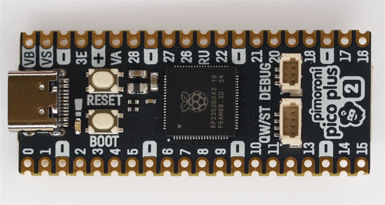
The photo below shows Pimoroni are using the 80-pin RP2350 chip for this board.
You can see the 3-pin debug connector (which connects to PicoProbe) on the top-right. Below it is a 4-pin connector that carries I2C, 3.3V and GND. The I2C connections are already exposed on a couple of the castellated pads, they are GPIO 4 and GPIO 5.

The underside contains the storage, RAM (a PSRAM chip), and an 8-pin JST-SH socket, which carries five extra GPIO (GPIO 32-36), 3.3V and the VSYS (e.g. 5V) and GND signals.

Here's the pinout, taken from the Pimoroni website:

Summary
The Pimoroni Pico Plus 2 board looks great, but it is not optimal for all projects. There are benefits and disadvantages.
I will definitely find uses for the Pimoroni Pico Plus 2 board, but some of its features will be overkill unless you've got a specific application in mind. If you need extra storage, you could solder a Flash memory chip onto a normal Pico or solder on a micro SD card, so there are workarounds. But it could be very convenient to have the storage and extra RAM all integrated if your project requires it.
To make the most use out of the board, you'll need a 3-pin JST connector if you want to more easily use the C/C++ SDK or hardware debug features, and an 8-pin JST connector if you need the extra five GPIO connections.
Thanks for reading.


Top Comments