element14 Community
element14 Community
    Register Log In
  • Site
  • Search
  • Log In Register
  • About Us
  • Community Hub
    Community Hub
    • What's New on element14
    • Feedback and Support
    • Benefits of Membership
    • Personal Blogs
    • Members Area
    • Achievement Levels
  • Learn
    Learn
    • Ask an Expert
    • eBooks
    • element14 presents
    • Learning Center
    • Tech Spotlight
    • STEM Academy
    • Webinars, Training and Events
    • Learning Groups
  • Technologies
    Technologies
    • 3D Printing
    • FPGA
    • Industrial Automation
    • Internet of Things
    • Power & Energy
    • Sensors
    • Technology Groups
  • Challenges & Projects
    Challenges & Projects
    • Design Challenges
    • element14 presents Projects
    • Project14
    • Arduino Projects
    • Raspberry Pi Projects
    • Project Groups
  • Products
    Products
    • Arduino
    • Avnet Boards Community
    • Dev Tools
    • Manufacturers
    • Multicomp Pro
    • Product Groups
    • Raspberry Pi
    • RoadTests & Reviews
  • Store
    Store
    • Visit Your Store
    • Choose another store...
      • Europe
      •  Austria (German)
      •  Belgium (Dutch, French)
      •  Bulgaria (Bulgarian)
      •  Czech Republic (Czech)
      •  Denmark (Danish)
      •  Estonia (Estonian)
      •  Finland (Finnish)
      •  France (French)
      •  Germany (German)
      •  Hungary (Hungarian)
      •  Ireland
      •  Israel
      •  Italy (Italian)
      •  Latvia (Latvian)
      •  
      •  Lithuania (Lithuanian)
      •  Netherlands (Dutch)
      •  Norway (Norwegian)
      •  Poland (Polish)
      •  Portugal (Portuguese)
      •  Romania (Romanian)
      •  Russia (Russian)
      •  Slovakia (Slovak)
      •  Slovenia (Slovenian)
      •  Spain (Spanish)
      •  Sweden (Swedish)
      •  Switzerland(German, French)
      •  Turkey (Turkish)
      •  United Kingdom
      • Asia Pacific
      •  Australia
      •  China
      •  Hong Kong
      •  India
      •  Korea (Korean)
      •  Malaysia
      •  New Zealand
      •  Philippines
      •  Singapore
      •  Taiwan
      •  Thailand (Thai)
      • Americas
      •  Brazil (Portuguese)
      •  Canada
      •  Mexico (Spanish)
      •  United States
      Can't find the country/region you're looking for? Visit our export site or find a local distributor.
  • Translate
  • Profile
  • Settings
Raspberry Pi
  • Products
  • More
Raspberry Pi
Blog Raspberry Pi B+ In Pictures
  • Blog
  • Forum
  • Documents
  • Quiz
  • Events
  • Polls
  • Files
  • Members
  • Mentions
  • Sub-Groups
  • Tags
  • More
  • Cancel
  • New
Join Raspberry Pi to participate - click to join for free!
Featured Articles
Announcing Pi
Technical Specifications
Raspberry Pi FAQs
Win a Pi
GPIO Pinout
Raspberry Pi Wishlist
Comparison Chart
Quiz
  • Share
  • More
  • Cancel
Group Actions
  • Group RSS
  • More
  • Cancel
Engagement
  • Author Author: Problemchild
  • Date Created: 16 Jul 2014 3:24 PM Date Created
  • Views 1445 views
  • Likes 2 likes
  • Comments 6 comments
Related
Recommended
  • b+
  • raspberry_pi
  • rpi

Raspberry Pi B+ In Pictures

Problemchild
Problemchild
16 Jul 2014

My Raspberry Pi B+ arrived yesterday so I thought I'd take a few photos of both the B+ and the changes but also how existing boars do do not fit the B+ design!
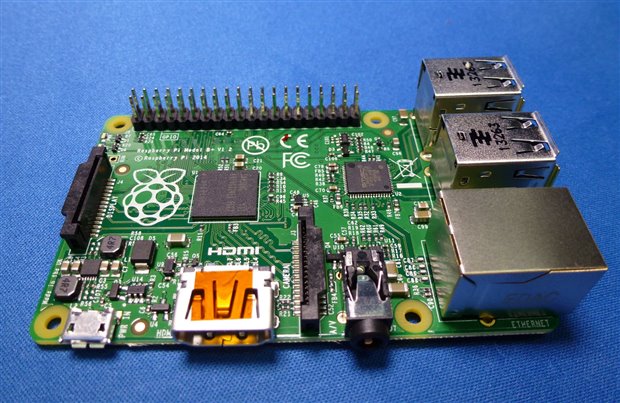
 

PI+  Full Frontal image

image


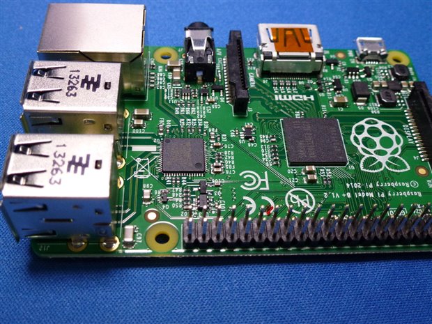
B+ Network (now with Blinkin' Lights) and the all important 4 USB ports

image


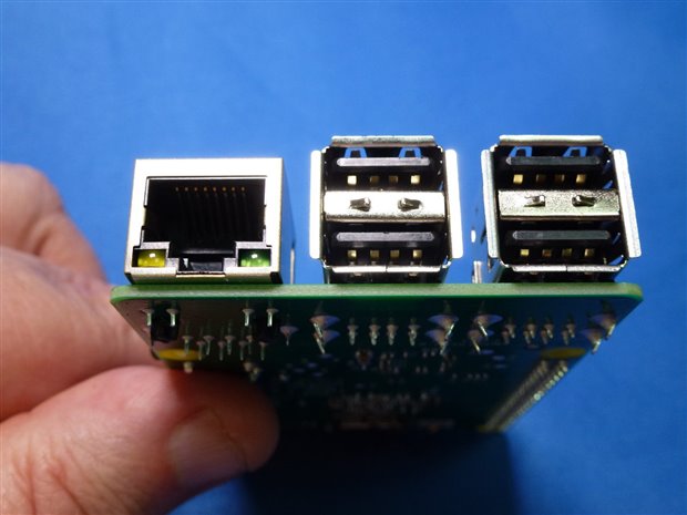
New 4 port USB Variant of the original 2 port device, Composite Phono has gone to be replaced with a 4 pole AV combo on the other side

image


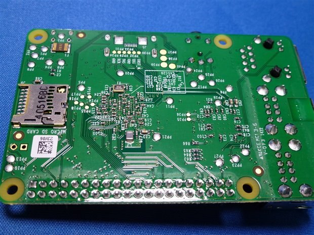
The Rear has been tided up and the full sized SDcard is replaced with a nice metal  micro SD push push device!

image


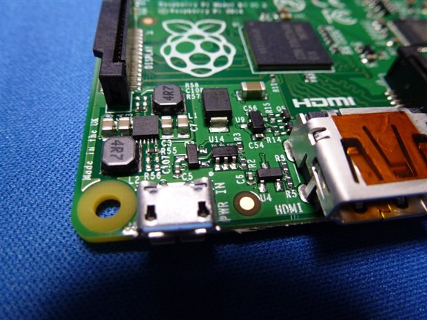
The Micro USB power connector is now on the same side as the HDMI and the Linear regulators replaced by this Switch mode.

Expect lower supply currents and hopefully reliability !!

image

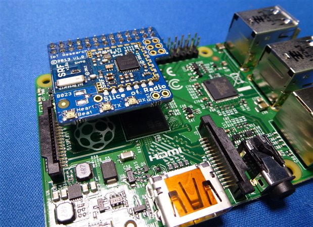
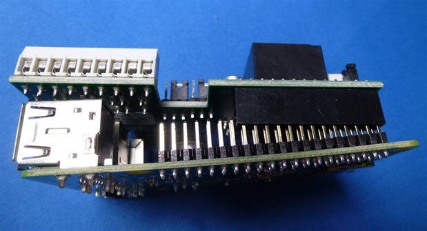
Small CISECO Radio board fits easily no problems

image

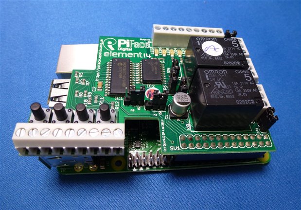
Unfortunately a no go with The PI Face Control and Display

image

image


Same for the Pi Face Digital

image


image


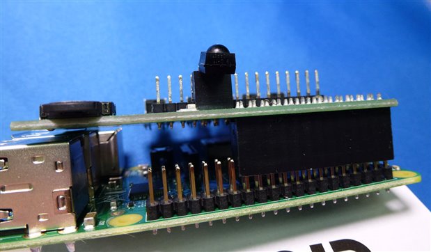
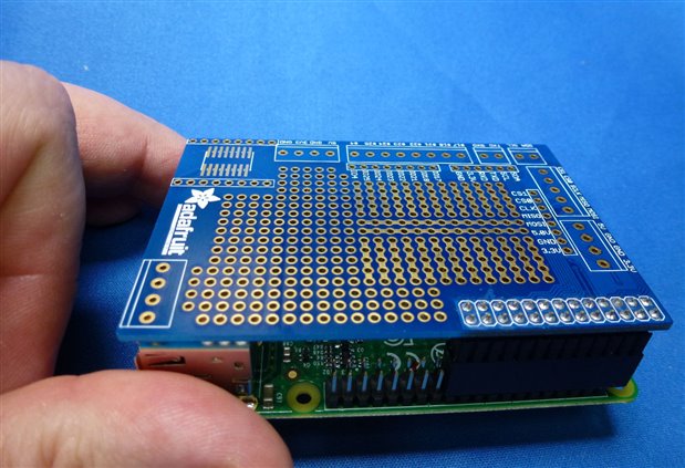
Adafruit's Prototyping board stands higher and thus is free of the board underneath and fits fine

image

(All images My copyright)


As you can see they a have taken many of the problems that existed in the B and have mitigated them in the B+.

The B+ is a true incremental release in this respect the extra USB ports and SMPs PSU should improve functionality and reliability.


Overall the physical layout changes are a great improvement  having connectors on only two sides will aid case designers and integrators alike. Large boards do foul the connectors some redesign is required for these (maybe a physical lift upwards??)


Extra I/O on the 40 pin connector should prove interesting as well!!

  • Sign in to reply

Top Comments

  • Problemchild
    Problemchild over 11 years ago in reply to shabaz +1
    Good idea also maybe having longer spills on the connector so it was proud of the connectors would be a move too. Damn we are planning a Pi B++ already
  • johnbeetem
    johnbeetem over 11 years ago in reply to mcb1 +1
    mcb1 wrote: So does anyone know what the two pin (unpopulated) connector labelled 'RUN' is for. (Its between the Display connector and ACT led at the edge of the board.) It's probably the same…
  • Problemchild
    Problemchild over 11 years ago in reply to mcb1 +1
    It's also in the Compute Pi documentation as well. Worth a look in general to find out a number of strange pins brought out and named on this device !
  • Problemchild
    Problemchild over 11 years ago in reply to mcb1

    It's also in the Compute Pi documentation as well.

    Worth a look in general to find out a number of strange pins brought out and named on this device !

    • Cancel
    • Vote Up +1 Vote Down
    • Sign in to reply
    • More
    • Cancel
  • mcb1
    mcb1 over 11 years ago in reply to johnbeetem

    It's probably the same 2-pin "P6" reset as on the rev 2.0 PCB

    I never noticed that one ..... thanks


    mark

    • Cancel
    • Vote Up 0 Vote Down
    • Sign in to reply
    • More
    • Cancel
  • johnbeetem
    johnbeetem over 11 years ago in reply to mcb1

    mcb1 wrote:


    So does anyone know what the two pin (unpopulated) connector labelled 'RUN' is for.

    (Its between the Display connector and ACT led at the edge of the board.)

    It's probably the same 2-pin "P6" reset as on the rev 2.0 PCB.  On the rev 2.0 schematic, the net pulled low by a reset switch is named RUN and is connected to the BCM2835 RUN pin.

    • Cancel
    • Vote Up +1 Vote Down
    • Sign in to reply
    • More
    • Cancel
  • mcb1
    mcb1 over 11 years ago

    So does anyone know what the two pin (unpopulated) connector labelled 'RUN' is for.

    (Its between the Display connector and ACT led at the edge of the board.)


    Also little mention of Class B certification now.

    Given the concerns raised in earlier conversations it seems to have been overlooked.


    Mark

    • Cancel
    • Vote Up 0 Vote Down
    • Sign in to reply
    • More
    • Cancel
  • Problemchild
    Problemchild over 11 years ago in reply to shabaz

    Good idea also maybe having longer spills on the connector so it was proud of the connectors would be a move too.


    Damn we are planning a Pi B++ already image

    • Cancel
    • Vote Up +1 Vote Down
    • Sign in to reply
    • More
    • Cancel
>
element14 Community

element14 is the first online community specifically for engineers. Connect with your peers and get expert answers to your questions.

  • Members
  • Learn
  • Technologies
  • Challenges & Projects
  • Products
  • Store
  • About Us
  • Feedback & Support
  • FAQs
  • Terms of Use
  • Privacy Policy
  • Legal and Copyright Notices
  • Sitemap
  • Cookies

An Avnet Company © 2025 Premier Farnell Limited. All Rights Reserved.

Premier Farnell Ltd, registered in England and Wales (no 00876412), registered office: Farnell House, Forge Lane, Leeds LS12 2NE.

ICP 备案号 10220084.

Follow element14

  • X
  • Facebook
  • linkedin
  • YouTube