element14 Community
element14 Community
    Register Log In
  • Site
  • Search
  • Log In Register
  • Members
    Members
    • Benefits of Membership
    • Achievement Levels
    • Members Area
    • Personal Blogs
    • Feedback and Support
    • What's New on element14
  • Learn
    Learn
    • Learning Center
    • eBooks
    • STEM Academy
    • Webinars, Training and Events
    • Learning Groups
  • Technologies
    Technologies
    • 3D Printing
    • FPGA
    • Industrial Automation
    • Internet of Things
    • Power & Energy
    • Sensors
    • Technology Groups
  • Challenges & Projects
    Challenges & Projects
    • Design Challenges
    • element14 presents
    • Project14
    • Arduino Projects
    • Raspberry Pi Projects
    • Project Groups
  • Products
    Products
    • Arduino
    • Dev Tools
    • Manufacturers
    • Raspberry Pi
    • RoadTests & Reviews
    • Avnet Boards Community
    • Product Groups
  • Store
    Store
    • Visit Your Store
    • Choose Another Store
      • Europe
      •  Austria (German)
      •  Belgium (Dutch, French)
      •  Bulgaria (Bulgarian)
      •  Czech Republic (Czech)
      •  Denmark (Danish)
      •  Estonia (Estonian)
      •  Finland (Finnish)
      •  France (French)
      •  Germany (German)
      •  Hungary (Hungarian)
      •  Ireland
      •  Israel
      •  Italy (Italian)
      •  Latvia (Latvian)
      •  
      •  Lithuania (Lithuanian)
      •  Netherlands (Dutch)
      •  Norway (Norwegian)
      •  Poland (Polish)
      •  Portugal (Portuguese)
      •  Romania (Romanian)
      •  Russia (Russian)
      •  Slovakia (Slovak)
      •  Slovenia (Slovenian)
      •  Spain (Spanish)
      •  Sweden (Swedish)
      •  Switzerland(German, French)
      •  Turkey (Turkish)
      •  United Kingdom
      • Asia Pacific
      •  Australia
      •  China
      •  Hong Kong
      •  India
      •  Korea (Korean)
      •  Malaysia
      •  New Zealand
      •  Philippines
      •  Singapore
      •  Taiwan
      •  Thailand (Thai)
      • Americas
      •  Brazil (Portuguese)
      •  Canada
      •  Mexico (Spanish)
      •  United States
      Can't find the country/region you're looking for? Visit our export site or find a local distributor.
  • Translate
  • Profile
Raspberry Pi
  • Products
  • More
Raspberry Pi
Blog Raspberry Pico as USB test device - part 3: add an additional SCPI query to get switch state
  • Blog
  • Forum
  • Documents
  • Events
  • Members
  • Mentions
  • Sub-Groups
  • Tags
  • More
  • Cancel
  • New
Raspberry Pi requires membership for participation - click to join
Blog Post Actions
  • Subscribe by email
  • More
  • Cancel
  • Share
  • Subscribe by email
  • More
  • Cancel
Group Actions
  • Group RSS
  • More
  • Cancel
Engagement
  • Author Author: Jan Cumps
  • Date Created: 4 Feb 2023 6:34 PM Date Created
  • Views 232 views
  • Likes 7 likes
  • Comments 2 comments
Related
Recommended
  • raspberry
  • pico_usbtmc_scpi
  • pico
  • scpi

Raspberry Pico as USB test device - part 3: add an additional SCPI query to get switch state

Jan Cumps
Jan Cumps
4 Feb 2023
Raspberry Pico as USB test device - part 3: add an additional  SCPI query to get switch state

In this post, I add a new SCPI query to the USBTMC and SCPI compliant instrument I developed for the Pico.
In the previous post, the device could switch outputs (or relays, ...) on or off with a SCPI command.
I'm now adding a SCPI command to retrieve the current state of a pin.

image
the image shows that non-LabVIEW applications detect and talk to the instrument too. Here: the Rigol Ultra Sigma suite

At the end of the blog you'll find the VSCode project with source and binaries.

You'll see that it's very easy to support new SCPI commands, once you have the basics working.

what we have until now: Existing SCPI command supported by the firmware

In the previous post, the project supported one SCPI command:

DIGI:OUTP# 0|1

This command turns a Pico GPIO output high or low.
# represents the channel you want to turn on or off. 

Example:

DIGI:OUTP2 1

This command drives the Pico GPIO output on channel 2 high. The channels are an index to an array of GPIO pins. I predefined 3 pins, but you can make an array of all the GPIOs. The firmware is (and because I wrote it: I am Nerd) smart enough to adapt to your array.

// supported pins
uint pins[] = {22, 14, 15};

The example SCPI command above would switch GPIO 15 high.

This is the code that does that:

static scpi_result_t SCPI_DigitalOutput(scpi_t * context) {


  scpi_bool_t param1;
  int32_t numbers[1];

  // retrieve the output index
  SCPI_CommandNumbers(context, numbers, 1, 0);
  if (! ((numbers[0] > -1) && (numbers[0] < pinCount()))) {
    SCPI_ErrorPush(context, SCPI_ERROR_INVALID_SUFFIX);
    return SCPI_RES_ERR;
  }

  /* read first parameter if present */
  if (!SCPI_ParamBool(context, &param1, TRUE)) {
    return SCPI_RES_ERR;
  }

  setPinAt(numbers[0], param1 ? true : false);

  return SCPI_RES_OK;
}

and this is how we tell the SCPI parser that the above function will handle the command:

    {.pattern = "DIGItal:OUTPut#", .callback = SCPI_DigitalOutput,},

what we add in this post: a new SCPI Query

I'm adding a new command that can query the state of a pin. The first command changed a state and did not give a reply. This one doesn't change the state of any pins, but does return a reply: the current pin state. The query command will look like this:

DIGI:OUTP#?

Alsmost the same as the set command, but without a parameter and with a question mark at the end.

First, let's write a function that returns the pin state. This is Pico specific. If you use another controller, you 'd use the API of that device.

bool isPinAt(uint32_t index) {
    return gpio_get_out_level(pins[index]);
}

Then the handler of the query command:

static scpi_result_t SCPI_DigitalOutputQ(scpi_t * context) {
  int32_t numbers[1];

  // retrieve the output index
  SCPI_CommandNumbers(context, numbers, 1, 0);
  if (! ((numbers[0] > -1) && (numbers[0] < pinCount()))) {
    SCPI_ErrorPush(context, SCPI_ERROR_INVALID_SUFFIX);
    return SCPI_RES_ERR;
  }

  SCPI_ResultBool(context, isPinAt(numbers[0]));
  return SCPI_RES_OK;
}

And as last step, train the SCPI parser:

    {.pattern = "DIGItal:OUTPut#?", .callback = SCPI_DigitalOutputQ,},

All the changes are simple. If this is hard to follow, comment on this post.

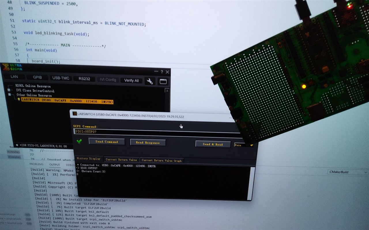
Test the added command

I used the NI-VISA  Interactive Control utility to test the new command. It's a great tool to verify if your instrulment will be supported by the major players.

1: Write Operation (*IDN?)
2: Read Operation
PICO-PI,LABSWITCH,0,01.00

3: Write Operation (DIGI:OUTP0 1)

4: Write Operation (DIGI:OUTP0?)
5: Read Operation
1

6: Write Operation (DIGI:OUTP0 0)

7: Write Operation (DIGI:OUTP0?)
8: Read Operation
0

I edited the log, removed additional info that the utility adds, and CRLFs

Success!

The attached project has additional changes. 

  • the *RST command is supported, and reinitialises all pins
  • the main file only deals with the USBTMC protocol, and exchanging data with the SCPI parser. It no longer has dependencies on (or knowledge of) the actual instrument.

VSCode project, sources and binaries

Here's the VSCode project archive. It contains the binary uf2 file. You can drag this on your Pico to program it without building from source.
Don't forget to add these two variables to your VSCode user environment:

image

7268.scpi_switch_usbtmc_20230204.zip

link to all posts

  • Sign in to reply
  • Jan Cumps
    Jan Cumps 1 month ago

    Using the LabVIEW VI driver I made for a similar design on a Pi (SCPI call compatible):

    You don't have permission to edit metadata of this video.
    Edit media
    x
    image
    Upload Preview
    image

    I didn't change any part of the LabVIEW  flow or code, just selected the Pico from the VISA selection box.
    It popped up in the values because the instrument implements the USBTMC profile.

    All VI blocks just worked.

    • Cancel
    • Vote Up 0 Vote Down
    • Sign in to reply
    • More
    • Cancel
  • Jan Cumps
    Jan Cumps 1 month ago

    Food for thought: 

    The lab switch is limited to the amount of GPIOs the Pico has. 
    If you need a vast switch device, you could use a set of I/O port ICs with i2c (or other) interface (I use an NXP PCA9557 for the SCPI eLoad).

    An additional advantage is that you can then use an i2c isolator, and have galvanic isolation between the Pico (and its USB  and the computer connected to it!) and the test circuit.

    • Cancel
    • Vote Up 0 Vote Down
    • Sign in to reply
    • More
    • Cancel
element14 Community

element14 is the first online community specifically for engineers. Connect with your peers and get expert answers to your questions.

  • Members
  • Learn
  • Technologies
  • Challenges & Projects
  • Products
  • Store
  • About Us
  • Feedback & Support
  • FAQs
  • Terms of Use
  • Privacy Policy
  • Legal and Copyright Notices
  • Sitemap
  • Cookies

An Avnet Company © 2023 Premier Farnell Limited. All Rights Reserved.

Premier Farnell Ltd, registered in England and Wales (no 00876412), registered office: Farnell House, Forge Lane, Leeds LS12 2NE.

ICP 备案号 10220084.

Follow element14

  • Facebook
  • Twitter
  • linkedin
  • YouTube