


Raspberry PIO stepper library (pio_stepper_lib) is a C++ library that runs stepper motors in PIO state machines. It's intended to be easy to integrate and use in Pico projects.
In this post: the frequency of the pulse train it generates, and how clock divider and delay change that.
Highest frequency
When you don't divide the PIO clock, it runs at the same speed as the Pico controller: 125 MHz*.
The PIO runs one instruction per tick. So an instruction takes 8 ns.
These are the instructions that generate the pulse:
tocks_h:
mov y, isr side 1 ; ISR contains number of tocks to hold level
count_high:
jmp y-- count_high side 1 [DELAY] ; keep high for tocks
tocks_l:
mov y, isr side 0 ; ISR contains number of tocks to hold level // TODO Note: not needed for both edges ...
count_low:
jmp y-- count_low side 0 [DELAY] ; keep high for tocks
jmp x-- tocks_h side 0 ; not done, keep looping
That's 5 instructions. DELAY is currently 0 in my design, so that can be ignored.
Without clock divider, the period per pulse: 5 * 8 ns = 40 ns -> 25 MHz.
Dividing the PIO clock will bring this down.
*the frequency used is of a Raspberry Pico 1 board, with no overclocking.
Understand the delay
In the PIO design, you can pass a delay to the PIO's isr register.
The design will then add delay * clock ticks to each halve period.
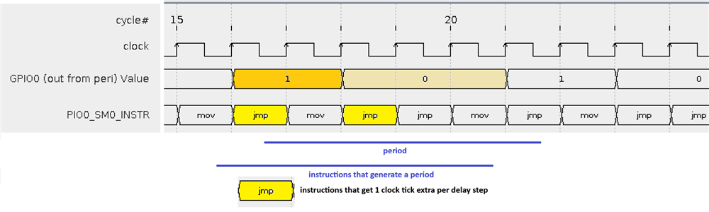
image: clock stretching mechanism explained
Without a clock divider, that adds 2 * 40 ns per count.
Let's say we set a delay of 5000 (and this delay is applied to both halves of the pulse).
period = 40 ns + 2 * 5000 ns = 10040 ns.
Step frequency is then approx 100 kHz. Although the resolution is fantasic - each delay step just adds 80 ns - the frequency is still way too high.
The delay is a 32 bit unsigned int, so you can really umph down the clock, with very precise resolution.
But for common designs, it's impractical.
Find a reasonable PIO clock and its minimum delay setting
If we divide the clock that feeds the PIO, we immediately come into a more workable range, still with decent resolution.
This is what I use for a full step design (where the stepper motor doesn't take micro-steps, but a full step each time.
My motor has 200 full steps per rotation
I defined clock divider as 16:
PIO clock = 125 MHz / 16 = 7812500 Hz
Period = 1/clock = 128 ns.
Without delay, a pulse takes 5 * 128 ns = 640 ns.
-> motor steps at 1562500 Hz. Still way too fast. But the 256 ns (2 * period) resolution is attractive.
Then I experimented until I found a divider that makes my motor step as fast as it can, without skipping a beat: 4300
Period = 640 ns + 2 * 4300 * 128 ns = 110144 ns
-> motor steps at 908 Hz. That's about the fastest my motor runs in full step mode.
It then does a 360° rotation (200 full steps) in 220 ms.
Each delay step adds 256 ns to that, and slows the motor down (because frequency is 1/time. adding time decreases frequency).
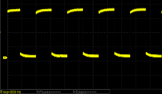
measurements confirm the calculations
some delays I used:
- 4300: fastest my motor steps
- 7000: fast, but slower
- 9000: fast, but even a little less fast
- 20000: slow.
Delay limit: 4294967295
Notes
The clock divider can be set per state machine. You can run 4 motors with different clock on each PIO. And then run each command with a different delay. This is flexible.
Each delay step adds 2 * period (= 2 * 1/f). There's a good reason to keep the PIO clock frequency high, because this time is spent for each (micro-)step.
Convention: get a PIO frequency that makes the motor go reliably at its fasted, with a delay of 4000.
There is a formula to calculate the period and frequency for each divider / delay combination. Maybe someone posts it in the comments?

