element14 Community
element14 Community
    Register Log In
  • Site
  • Search
  • Log In Register
  • Community Hub
    Community Hub
    • What's New on element14
    • Feedback and Support
    • Benefits of Membership
    • Personal Blogs
    • Members Area
    • Achievement Levels
  • Learn
    Learn
    • Ask an Expert
    • eBooks
    • element14 presents
    • Learning Center
    • Tech Spotlight
    • STEM Academy
    • Webinars, Training and Events
    • Learning Groups
  • Technologies
    Technologies
    • 3D Printing
    • FPGA
    • Industrial Automation
    • Internet of Things
    • Power & Energy
    • Sensors
    • Technology Groups
  • Challenges & Projects
    Challenges & Projects
    • Design Challenges
    • element14 presents Projects
    • Project14
    • Arduino Projects
    • Raspberry Pi Projects
    • Project Groups
  • Products
    Products
    • Arduino
    • Avnet & Tria Boards Community
    • Dev Tools
    • Manufacturers
    • Multicomp Pro
    • Product Groups
    • Raspberry Pi
    • RoadTests & Reviews
  • About Us
    About the element14 Community
  • Store
    Store
    • Visit Your Store
    • Choose another store...
      • Europe
      •  Austria (German)
      •  Belgium (Dutch, French)
      •  Bulgaria (Bulgarian)
      •  Czech Republic (Czech)
      •  Denmark (Danish)
      •  Estonia (Estonian)
      •  Finland (Finnish)
      •  France (French)
      •  Germany (German)
      •  Hungary (Hungarian)
      •  Ireland
      •  Israel
      •  Italy (Italian)
      •  Latvia (Latvian)
      •  
      •  Lithuania (Lithuanian)
      •  Netherlands (Dutch)
      •  Norway (Norwegian)
      •  Poland (Polish)
      •  Portugal (Portuguese)
      •  Romania (Romanian)
      •  Russia (Russian)
      •  Slovakia (Slovak)
      •  Slovenia (Slovenian)
      •  Spain (Spanish)
      •  Sweden (Swedish)
      •  Switzerland(German, French)
      •  Turkey (Turkish)
      •  United Kingdom
      • Asia Pacific
      •  Australia
      •  China
      •  Hong Kong
      •  India
      •  Japan
      •  Korea (Korean)
      •  Malaysia
      •  New Zealand
      •  Philippines
      •  Singapore
      •  Taiwan
      •  Thailand (Thai)
      •  Vietnam
      • Americas
      •  Brazil (Portuguese)
      •  Canada
      •  Mexico (Spanish)
      •  United States
      Can't find the country/region you're looking for? Visit our export site or find a local distributor.
  • Translate
  • Profile
  • Settings
Raspberry Pi
  • Products
  • More
Raspberry Pi
Raspberry Pi Forum Raspberry Pi - Hardware Flaws and Fixups?
  • Blog
  • Forum
  • Documents
  • Quiz
  • Events
  • Polls
  • Files
  • Members
  • Mentions
  • Sub-Groups
  • Tags
  • More
  • Cancel
  • New
Join Raspberry Pi to participate - click to join for free!
Featured Articles
Announcing Pi
Technical Specifications
Raspberry Pi FAQs
Win a Pi
Raspberry Pi Wishlist
Actions
  • Share
  • More
  • Cancel
Forum Thread Details
  • Replies 188 replies
  • Subscribers 717 subscribers
  • Views 22834 views
  • Users 0 members are here
  • flaws
  • hardware
  • single_board_computer
  • single_board_computers
  • raspberry_pi
  • Design
  • fixups
Related

Raspberry Pi - Hardware Flaws and Fixups?

e14 Contributor
e14 Contributor over 14 years ago

Several people have commented on the hardware design of the Raspberry Pi.  Some are buried in other topics so please post your comments here.  I'll try my best to answer questions about the design decisions we made.  The Raspberry Pi is not perfect, never will be.  I've always found that perfect designs have a habit of never getting built, engineers are always a bit guilty of that, but I had Eben phoning/emailing me every day wanting to know when it would be finished.  Also, one persons perfection is another persons nightmare.


e14 is the home for engineers so please contribute to make Raspberry Pi better.


Thanks


Pete

  • Sign in to reply
  • Cancel
Parents
  • morgaine
    morgaine over 14 years ago

    Now that people have actually started receiving the boards so the design in final, is the schematic close to being posted?  I looked around again in various likely places just now, but haven't spotted it yet.

    • Cancel
    • Vote Up 0 Vote Down
    • Sign in to reply
    • Cancel
  • e14 Contributor
    e14 Contributor over 14 years ago in reply to morgaine

    actually, the design may not be quite final yet.  Liz said: "Happily, we’ve found it doesn’t need a shielded enclosure to reach Class B, although it will require a (very minimal) redesign." http://www.raspberrypi.org/archives/978, page 3, April 10, 2012 at 7:04 pm.


    It hasn't been announced when such a change might be implemented, but probably better sooner rather than later, given the large production runs planned, perhaps along with a change to fix the SD card voltage issue.

    • Cancel
    • Vote Up 0 Vote Down
    • Sign in to reply
    • Cancel
  • rew
    rew over 14 years ago in reply to e14 Contributor

    Hi Pete,


    If you're interested, I would think that people who are having troubles are using a power cable or power supply that isn't good enough.

    You must be aware that I and others have measured cables at 3-5 Ohms. That is surely not going to work out well.


    I haven't measured the average current yet, but it could very well be about 0.3A. With a 1 Ohm cable and a 5.1V powersupply that would lead to the 4.8V that someone measured with a multimeter.


    However a burst of 0.7A will then deplete the 220uF in under half a millisecond. (I'm assuming a 0.7V dropout for the 3.3V regulator). That's way too fast to measure with a multimeter. And it's way long enough to brown-out the CPU and/or LAN chip.

    • Cancel
    • Vote Up 0 Vote Down
    • Sign in to reply
    • Cancel
  • e14 Contributor
    e14 Contributor over 14 years ago in reply to rew

    Roger & All


    I'm seeing a few issues relating to this 'brownout' problem.  I've got someone looking at this with fast scope and a selection of cables / PSU's to try to bottom this.  We have not seen this problem in our test set but that is the joy of putting something in the field.


    I'm also trying to get a handle on the population of users that have a problem with this.  Interestingly in one of the tests we did is to run the board w/o the 220uF present and it still worked without problems - so you could be onto something.


    Thanks for the input.


    Pete

    • Cancel
    • Vote Up 0 Vote Down
    • Sign in to reply
    • Cancel
  • e14 Contributor
    e14 Contributor over 14 years ago in reply to rew

    Roger you wrote: "However next in line is my I2C interface. This too is labeled on the GPIO port as: I2C SDA, I2C SCL, and I'll have to guess which of the several I2C interfaces is connected to the GPIO pins"

    The wiki says the I2C are SDA0 SCL0 !

    Are planning on doing an I2C driver?

    I have a batch of Real Time Clock modules that I'd to love to start selling but would like to get them tested on an R-Pi first!


    Or is anyone else with an R-Pi /getting in the next batch, interested in writing an I2C driver? If yes please email me: chris@cjemicros.co.uk

    I'm told that the Linux sources have a driver for the DS1338 that I've used! (there is also support in the RISC OS sources which is how we have tested our design)

    • Cancel
    • Vote Up 0 Vote Down
    • Sign in to reply
    • Cancel
  • rew
    rew over 14 years ago in reply to e14 Contributor

    Hi Chris,

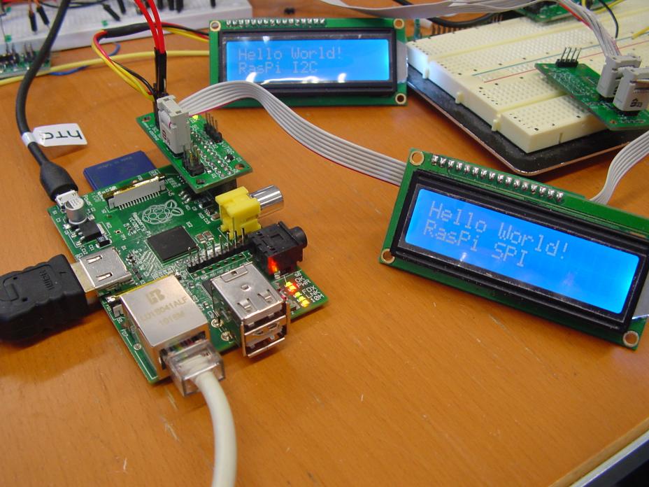
    I've gotten I2C working now from the commandline "bitibanging" utility. I was just browsing around on the forum to find a place where I can post a link to the software. :-)

    Which reminds me: I don't have I2C read implemented yet....[time passes] .... OK. Done! :-)


    Here are the commandline utilities to control GPIO, SPI and I2C.

    http://www.bitwizard.nl/software/gpio_spi_i2c_20120419.tgz

    Some sample scripts are included to make it easy to work with my I2c and SPI boards.


    http://prive.bitwizard.nl/dsc04617_small.jpg


    I'll start looking into writing the I2C and SPI kernel drivers shortly.


    It could very well be that I decide that what I want from a kernel driver is not what the standard I2C and SPI kernel drivers do. I want to be able to easily, from userspace, interact with the devices on the bus. Eventually it should be something like:

    echo 1 > /dev/motor

    and the motor starts turning. :-)


    OT: Chris, your name sounds familiar. Were you involved with Linux in the early years? Google shows that there is an actor with your name too. (or is that you?) :-)

    • Cancel
    • Vote Up +1 Vote Down
    • Sign in to reply
    • Cancel
  • e14 Contributor
    e14 Contributor over 14 years ago in reply to rew

    Great work Roger! I've emailed you via the bitwizard site.

    There are a few Chris Evans's about. I'm new to Linux!

    • Cancel
    • Vote Up 0 Vote Down
    • Sign in to reply
    • Cancel
  • e14 Contributor
    e14 Contributor over 14 years ago in reply to rew

    Ha, I already wondered how long it would take you, to show something like this.... image

    I think it is a good picture for the frontpage on raspberrypi.org....


    Can you perhaps measure the pcb for me. I am getting different answers from people.

    Best guess now is  85.0 x 56.0   or  85.0 x 56.2


    Hans


    Raspberry Pi forum :  custom cases
    Shapeways: picases
    Thingiverse : 3D printer case
    Thingiverse :Pi Lego blocks
    • Cancel
    • Vote Up 0 Vote Down
    • Sign in to reply
    • Cancel
  • e14 Contributor
    e14 Contributor over 14 years ago in reply to e14 Contributor

    Observation about USB power supplies: not sure if relevant to RasPi or not.

    I was making some load measurements on a bunch of 5V USB power supplies here, unrelated to RasPi stuff. Got some confusing results, until I realized something I didn't know: some of those cable-less "wall wart" USB power supplies with just a USB jack, connect the internal ground pin (cable black wire) to the connector shield (cable braid), and some do not. So in some cases you'll have the ground return current flowing on the shield (if your device connects ground and shield) and in some cases, not. In case of interest.

    • Cancel
    • Vote Up 0 Vote Down
    • Sign in to reply
    • Cancel
  • e14 Contributor
    e14 Contributor over 14 years ago in reply to e14 Contributor

    Thanks for all the info Pete. A summary of possible 'minor' hardware changes that I've spotted in the forums:


    1. I2S implement  as per the data sheet


    2. SD card voltage option bank change, as per Dom's posting in: http://www.raspberrypi.org/forum/general-discussion/where-is-the-bottleneck#p62401


    3. USB OTG Id Pin to spare GPIO pin (effective only on Model A) as per:

    http://www.raspberrypi.org/forum/features-and-requests/cheap-but-crucial-model-a-feature-request-read-this?value=gpio%20usb%20pin%20request&type=2&include=1&search=1&ret=all


    I'm not sure if the next two are technically possible!


    4. Assisting POE (spare wires variant) adaptors exist that inject power onto the unused lines of ethernet and then split them out again after a cable

    run see: http://www.cjemicros.co.uk/micros/individual/newprodpages/prodinfo.php?prodcode=4D-RPI-POE-IS-C (The Raspberry Pi adaptor cables doubles the price!) but if R-Pi's RJ45 could be changed for a variant that took the extra lines Earth to R-Pi's Earth and the Injected Power lines to R-Pi 5V via a link.


    Pros: simple for end users to setup and injector only cable should be cheap.

    Cons: POE variant of RJ45 with magnetics needed [1], cost, Reduced Isolation and extra link needed.


    5. Assisting POE (via GPIO daughter board) If a POE daughter board was plugged into the GPIO pins with the daughter board having a POE input

    RJ45 on it, supplying power to the R-Pi. The four ethernet data line output from the daughter board being connected to currently unused GPIO pins. I suspect inputting ethernet via the GPIO pins breaks various rules and could add to RF output:-(

    Original suggestion at: http://www.raspberrypi.org/forum/features-and-requests/routing-ethernet-pins-4578-to-the-expansion-port


    [1] I found a mag jack that might the type needed at: http://www.adam-tech.com/catalog/2012/page_009-049.pdf

    See page 37 of 41 (marked Page 45) layout M16


    n.b. I'm intrigued, what do the two diodes on the underside near the USB sockets protect?

    I'd thought the USB ports, but people have mentioned on the forums that they have (unreliably) powered R-Pis via one of the two USB ports.

    • Cancel
    • Vote Up 0 Vote Down
    • Sign in to reply
    • Cancel
  • e14 Contributor
    e14 Contributor over 14 years ago in reply to e14 Contributor

    mmm, I really hope those "power issues" turn out to be just bad cable/adaptors/ppl doing it wrong.

    You guys are working on it I suppose.

    btw PeteL, what is requiring redesign (for full compliance)? That's what is bugging me, since it leads to another question: when will this be implemented (and then re-certified)? Before or after the queue of orders?

    I guess "what are the changes needed" is more your cup of coffee (or better tea), so that's what I'd really like you to enlight me on.


    Btw, is it just me or those 2k units feel a lot like a pre-serie?

    • Cancel
    • Vote Up 0 Vote Down
    • Sign in to reply
    • Cancel
  • rew
    rew over 14 years ago in reply to e14 Contributor

    "those 2K" should be "those 10k". The other 8k are Guaranteed to be exactly the same: they were produced feb-march just like the first 2k that are delivered right now.


    and yes, I too would want to know what changes seem to be neccessary and when they will go through.


    What is the HD interface? (schematics P4 left top)


    What value is typical for the built-in pullup/pulldown? I expect that to be on the order of 50-100k. In that case you can encode 3^4 different board revisions with the 4 board-revision strap resistors:

    read value. If zero, enable pullup, if one enable pulldown. If value now changes, the strap is left "open", so that's the third value.  (Ah! found them!).


    There is an error in the schematics. p3 mentions the "USB" part of the LAN9512 as "model A only". That should be "Model B only" of course.


    R22-R25, R28, C28 are missing their "Model B only" tag.


    Why is there a line going from R25 to R22?


    Due to space constraints the 100M led is labeled 10M on the board. How about calling that "FE" for "Fast Ethernet"? That's what 100M was called back in the days.


    On the other hand, I would much rather have a BCM2835 GPIO pin control a led in that position. If we want, we can program it for the 100M/FE function in software, but it provides those who are going "bare bones" with an extra debugging option.


    Similarly, the FDX led is nowadays a bit outdated. Why on earth are we still interested in that statusbit? Any reasonably recent setup will run full duplex, and it won't help in debugging in seeing that led remain off. Again: A gpio LED would be a nice replacement. The easiest way to notice a halff duplex link is to watch "dmesg": smsc95xx 1-1.1:1.0: eth0: link up, 100Mbps, full-duplex, lpa 0xC5E1


    What is the purpose of D15, D16? I'm thinking: Protection against static discharges, right? The question is: Wouldn't it be better to connect their kathode to +5V0 instead of +5V0_HDMI? The +5V_HDMI is just a small net that only has the 100N C75 on it....


    Are the HDMI_SDA and HDMI_SCL pins 5V tolerant? I wouldn't have guessed.

    • Cancel
    • Vote Up 0 Vote Down
    • Sign in to reply
    • Cancel
Reply
  • rew
    rew over 14 years ago in reply to e14 Contributor

    "those 2K" should be "those 10k". The other 8k are Guaranteed to be exactly the same: they were produced feb-march just like the first 2k that are delivered right now.


    and yes, I too would want to know what changes seem to be neccessary and when they will go through.


    What is the HD interface? (schematics P4 left top)


    What value is typical for the built-in pullup/pulldown? I expect that to be on the order of 50-100k. In that case you can encode 3^4 different board revisions with the 4 board-revision strap resistors:

    read value. If zero, enable pullup, if one enable pulldown. If value now changes, the strap is left "open", so that's the third value.  (Ah! found them!).


    There is an error in the schematics. p3 mentions the "USB" part of the LAN9512 as "model A only". That should be "Model B only" of course.


    R22-R25, R28, C28 are missing their "Model B only" tag.


    Why is there a line going from R25 to R22?


    Due to space constraints the 100M led is labeled 10M on the board. How about calling that "FE" for "Fast Ethernet"? That's what 100M was called back in the days.


    On the other hand, I would much rather have a BCM2835 GPIO pin control a led in that position. If we want, we can program it for the 100M/FE function in software, but it provides those who are going "bare bones" with an extra debugging option.


    Similarly, the FDX led is nowadays a bit outdated. Why on earth are we still interested in that statusbit? Any reasonably recent setup will run full duplex, and it won't help in debugging in seeing that led remain off. Again: A gpio LED would be a nice replacement. The easiest way to notice a halff duplex link is to watch "dmesg": smsc95xx 1-1.1:1.0: eth0: link up, 100Mbps, full-duplex, lpa 0xC5E1


    What is the purpose of D15, D16? I'm thinking: Protection against static discharges, right? The question is: Wouldn't it be better to connect their kathode to +5V0 instead of +5V0_HDMI? The +5V_HDMI is just a small net that only has the 100N C75 on it....


    Are the HDMI_SDA and HDMI_SCL pins 5V tolerant? I wouldn't have guessed.

    • Cancel
    • Vote Up 0 Vote Down
    • Sign in to reply
    • Cancel
Children
  • e14 Contributor
    e14 Contributor over 14 years ago in reply to rew

    On the other hand, I would much rather have a BCM2835 GPIO pin control a led in that position. If we want, we can program it for the 100M/FE function in software, but it provides those who are going "bare bones" with an extra debugging option.


    Similarly, the FDX led is nowadays a bit outdated. Why on earth are we still interested in that statusbit? Any reasonably recent setup will run full duplex, and it won't help in debugging in seeing that led remain off. Again: A gpio LED would be a nice replacement. The easiest way to notice a halff duplex link is to watch "dmesg": smsc95xx 1-1.1:1.0: eth0: link up, 100Mbps,full-duplex, lpa 0xC5E1


    I agree with that, FDX led is not really usefull, it would be much better if that could be used as a gpio led.

    That way you can directly let kids program the led without the need for extra hardware.

    Hans


    Raspberry Pi forum :  custom cases
    Shapeways: picases
    Thingiverse : 3D printer case
    Thingiverse :Pi Lego blocks
    • Cancel
    • Vote Up 0 Vote Down
    • Sign in to reply
    • Cancel
  • johnbeetem
    johnbeetem over 14 years ago in reply to e14 Contributor

    Well, in principle you can use the FDX as a GPIO LED.  The difficulty is that you need to talk to the LAN9512 in USB-speak to configure and toggle it, and the driver may make this difficult.  Still, students would learn a lot about USB drivers trying to do it :-)

    • Cancel
    • Vote Up 0 Vote Down
    • Sign in to reply
    • Cancel
  • rew
    rew over 14 years ago in reply to johnbeetem

    Was it here that someone asked me to measure the physical size of the 'pi? Mine is 55.9 x 84.9mm.

    • Cancel
    • Vote Up 0 Vote Down
    • Sign in to reply
    • Cancel
  • e14 Contributor
    e14 Contributor over 14 years ago in reply to rew

    Yes me...  thx Roger.


    Hans


    Raspberry Pi forum :  custom cases
    Shapeways: picases
    Thingiverse : 3D printer case
    Thingiverse :Pi Lego blocks
    • Cancel
    • Vote Up 0 Vote Down
    • Sign in to reply
    • Cancel
  • Montala
    Montala over 14 years ago in reply to rew

    I know it is only slightly different, and may not matter at all, but in a post on the Raspberrypi.org website one recipient (another case manufacturer actually) has said that: The board is 85.00 x 56.17


    • Cancel
    • Vote Up 0 Vote Down
    • Sign in to reply
    • Cancel
  • e14 Contributor
    e14 Contributor over 14 years ago in reply to Montala

    Hi David, yes I know   ModMyPi measured that....  That is why I asked Roger... I know he is very precise...

    So probably the pcb board is 85.0 x 56.0  with 0.2 tolerance

    All my cases are made 85.6 x 56.0, and I have 4 lying here waiting.... but I was not that lucky in getting a Pi...

    So the pcb will fit,  even if it is .17 wider I can probably shave a little off the pcb board...


    Hans


    Raspberry Pi forum :  custom cases
    Shapeways: picases
    Thingiverse : 3D printer case
    Thingiverse :Pi Lego blocks
    • Cancel
    • Vote Up 0 Vote Down
    • Sign in to reply
    • Cancel
  • e14 Contributor
    e14 Contributor over 14 years ago in reply to e14 Contributor

    The schematic doesn't appear to show the memory chip-select lines,

    but Gert has mentioned that the SoC has only a single chip-select line,

    which prevents stacking more than one memory chip, as described here:

    http://www.engadget.com/2011/03/25/samsung-starts-baking-30nm-4gb-lpddr2-chips-packaging-2gb-mobil/


    Are the production volumes large enough now that Broadcom might consider

    presumably minor changes such as adding an additional chip-select line?

    • Cancel
    • Vote Up 0 Vote Down
    • Sign in to reply
    • Cancel
  • e14 Contributor
    e14 Contributor over 14 years ago in reply to e14 Contributor

    The schematic does not show any of the connections to the Package on Package (POP) memory that actually sits on top of the BCM2835.  It never gets to the PCB so there is just a hidden attribute that calls up the part onto the parts list so it doesn't get forgotten!  I think I should make reference to that on the next schematic set.


    More than one chip select would not be of any use unless a memory manufacturer decided to make a DRAM chip that passed through all the signals (and the additional chip select) to a package that sits above.


    Theoretically it is possible, and there are examples of Package on Package on Package.  It's not uncommon for this to be done inside a single package (stacked die) but the interconnect is done usually with bond wires.


    Unless we pass the 4-5 Million Pi's mark with no obvious tailing off of demand I think Broadcom would not be interested, I suspect the number is in reality much higher than this.  Making even a minor mod to silicon can cost millions of dollars.  One of the big costs used to be a mask set, but now I think direct imaging has taken this out of the loop. I'm sure there are people on the forum who could comment better than me - I just use the chips now. 


    I used to make silicon but the advent of cheap (relatively) programmable logic (FPGAs)  has largely chopped away the mid volume market.  The stress of waiting for a PCB spin is nothing compared to 'first off' silicon - hats off to those guys, I'm to old to suffer that now!  You can fix a multitude of sins in an FPGA.image


    One option discussed before is to use a larger capacity POP memory chip but for the moment this is not in the roadmap.


    Cheers


    Pete

    • Cancel
    • Vote Up +1 Vote Down
    • Sign in to reply
    • Cancel
  • e14 Contributor
    e14 Contributor over 14 years ago in reply to e14 Contributor

    The engadget article I cited mentions getting 1GB by stacking 2 4Gb memory chips,

    where otherwise stacking 4 2Gb chips would be required.  I'm not sure if that involves

    multiple chip-select lines or not.  I'm also not certain what memory parts are actually

    available since this article.

    • Cancel
    • Vote Up 0 Vote Down
    • Sign in to reply
    • Cancel
  • e14 Contributor
    e14 Contributor over 14 years ago in reply to e14 Contributor

    Looking at the article it looked like this is a stacked die ('chip') application inside a single package - should have made this clear in the previous post.  The BGA ball array is set up for Standard Mobile and not to sit on a POP architecture so I think we are out of luck here.


    Pete

    • Cancel
    • Vote Up 0 Vote Down
    • Sign in to reply
    • Cancel
element14 Community

element14 is the first online community specifically for engineers. Connect with your peers and get expert answers to your questions.

  • Members
  • Learn
  • Technologies
  • Challenges & Projects
  • Products
  • Store
  • About Us
  • Feedback & Support
  • FAQs
  • Terms of Use
  • Privacy Policy
  • Legal and Copyright Notices
  • Sitemap
  • Cookies

An Avnet Company © 2026 Premier Farnell Limited. All Rights Reserved.

Premier Farnell Ltd, registered in England and Wales (no 00876412), registered office: Farnell House, Forge Lane, Leeds LS12 2NE.

Follow element14

  • X
  • Facebook
  • linkedin
  • YouTube