element14 Community
element14 Community
    Register Log In
  • Site
  • Search
  • Log In Register
  • Community Hub
    Community Hub
    • What's New on element14
    • Feedback and Support
    • Benefits of Membership
    • Personal Blogs
    • Members Area
    • Achievement Levels
  • Learn
    Learn
    • Ask an Expert
    • eBooks
    • element14 presents
    • Learning Center
    • Tech Spotlight
    • STEM Academy
    • Webinars, Training and Events
    • Learning Groups
  • Technologies
    Technologies
    • 3D Printing
    • FPGA
    • Industrial Automation
    • Internet of Things
    • Power & Energy
    • Sensors
    • Technology Groups
  • Challenges & Projects
    Challenges & Projects
    • Design Challenges
    • element14 presents Projects
    • Project14
    • Arduino Projects
    • Raspberry Pi Projects
    • Project Groups
  • Products
    Products
    • Arduino
    • Avnet & Tria Boards Community
    • Dev Tools
    • Manufacturers
    • Multicomp Pro
    • Product Groups
    • Raspberry Pi
    • RoadTests & Reviews
  • About Us
  • Store
    Store
    • Visit Your Store
    • Choose another store...
      • Europe
      •  Austria (German)
      •  Belgium (Dutch, French)
      •  Bulgaria (Bulgarian)
      •  Czech Republic (Czech)
      •  Denmark (Danish)
      •  Estonia (Estonian)
      •  Finland (Finnish)
      •  France (French)
      •  Germany (German)
      •  Hungary (Hungarian)
      •  Ireland
      •  Israel
      •  Italy (Italian)
      •  Latvia (Latvian)
      •  
      •  Lithuania (Lithuanian)
      •  Netherlands (Dutch)
      •  Norway (Norwegian)
      •  Poland (Polish)
      •  Portugal (Portuguese)
      •  Romania (Romanian)
      •  Russia (Russian)
      •  Slovakia (Slovak)
      •  Slovenia (Slovenian)
      •  Spain (Spanish)
      •  Sweden (Swedish)
      •  Switzerland(German, French)
      •  Turkey (Turkish)
      •  United Kingdom
      • Asia Pacific
      •  Australia
      •  China
      •  Hong Kong
      •  India
      • Japan
      •  Korea (Korean)
      •  Malaysia
      •  New Zealand
      •  Philippines
      •  Singapore
      •  Taiwan
      •  Thailand (Thai)
      • Vietnam
      • Americas
      •  Brazil (Portuguese)
      •  Canada
      •  Mexico (Spanish)
      •  United States
      Can't find the country/region you're looking for? Visit our export site or find a local distributor.
  • Translate
  • Profile
  • Settings
Raspberry Pi
  • Products
  • More
Raspberry Pi
Raspberry Pi Forum More power/heat related problems ...
  • Blog
  • Forum
  • Documents
  • Quiz
  • Events
  • Polls
  • Files
  • Members
  • Mentions
  • Sub-Groups
  • Tags
  • More
  • Cancel
  • New
Join Raspberry Pi to participate - click to join for free!
Featured Articles
Announcing Pi
Technical Specifications
Raspberry Pi FAQs
Win a Pi
Raspberry Pi Wishlist
Actions
  • Share
  • More
  • Cancel
Forum Thread Details
  • Replies 15 replies
  • Subscribers 677 subscribers
  • Views 2481 views
  • Users 0 members are here
  • raspberry
  • heat
  • issues
  • raspberry_pi
  • raspberrypi
  • thermal
  • power
Related

More power/heat related problems ...

jamodio
jamodio over 13 years ago

I think I found another problem I didn't notice before.


I have the R-pi hooked up in the prototyping gig I described on another thread (http://www.element14.com/community/thread/18981?tstart=0),

currently no keyboard, HDMI monitor, just network and access to console via the serial port.


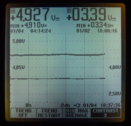
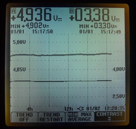
I've been running a trend plot monitoring the +5V feed to the R-pi and the output of the 3.3V on board regulator. I noticed that gradually

the voltage out of the regulator has increased from 3.30V to almost 3.39V, it is actually not doing much, just responding to ping packtes

(flood mode) I'm sending from another machine and serving the serial console I use once in a while to run procinfo and network stats.


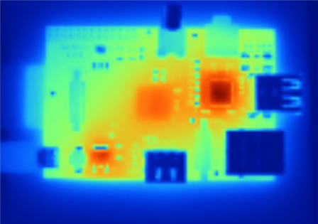
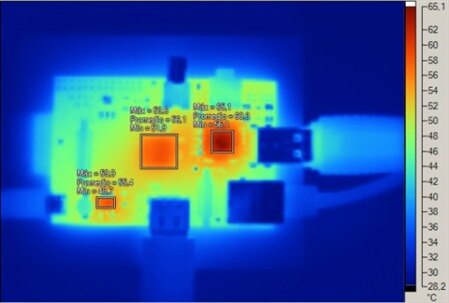
I guess the voltage increase is probably not noticeable when there is more load and current draw, the only thing I can think of is self

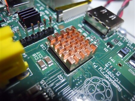
heating of the LDO. I just placed one of the little heatsinks I've got for the LAN9512 on the LDO and seems that output voltage is starting

to slowly drop. I'll keep this configuration to see if with the heatsink the voltage keeps droping.


image


-J

  • Sign in to reply
  • Cancel
Parents
  • jamodio
    jamodio over 13 years ago

    Still can't explain it but something is going on, over a period of 40 hours the output of RG2 has been increasing from 3.34V to 3.39V,

    temperature shows now 44.2C and trending up. This is without the heatsink.


    image


    I'm tempted to replace the part and see what happens.


    -J

    • Cancel
    • Vote Up 0 Vote Down
    • Sign in to reply
    • Cancel
  • Former Member
    Former Member over 13 years ago in reply to jamodio

    You have looked for instability (HF oscillations) with your scope? These issues can be down to (input /) output capacitors. Maybe reflow the solder on these components as well as the regulator. Looking at the trace your 5V line seems to be trending upwards as well?


    I assume that you have double checked your readings against another measuring device? Or against another piece of kit with a similar regulator. Its just that the 3.34V start value is out of spec to start with.


    For the cost of these things if you are comfortable doing the job then what's to lose. Looks as though its easy to get at as well.

    • Cancel
    • Vote Up 0 Vote Down
    • Sign in to reply
    • Cancel
  • jamodio
    jamodio over 13 years ago in reply to Former Member

    Still not a definitive explanation but I believe the issue is ambient temperature, I'm cranking up the air conditioner to reduce my office temperature from about 27C to 25C and now the output of RG2 shows 3.36V.


    I think that since there are several components generating heat and it gets conducted through the power planes, it may generate sort of a cascading event where the internal temperature of some parts start to trigger side effects.


    I'll hookup the rework station at some moment to replace the part and test with other regulators I've believe have in stock with the same package.


    While the part number on the schematics is shown as NCP1117, the part installed on at least the two boards I've is numbered SE8117T33, which is not from any well known major semiconductor company but a chinese cheap knock off, it could also be a counterfit part, not uncommon when sourcing some parts from China.


    This thermal image taken by "Remy" from Spain shows really where the heat is, if you follow the orange haze you can see how heat is being conducted by the board and not just staying around the hot components.


    image


    I wonder how many Raspberry Pi's will get "cooked" when people start to put them in cases.


    -J

    • Cancel
    • Vote Up +1 Vote Down
    • Sign in to reply
    • Cancel
  • morgaine
    morgaine over 13 years ago in reply to jamodio

    Interesting image, where was that posted?  Any more info, like the temperature of the LAN9512 at the time?

    • Cancel
    • Vote Up 0 Vote Down
    • Sign in to reply
    • Cancel
  • jamodio
    jamodio over 13 years ago in reply to morgaine

    The original post is in spanish. Here is the link ...

    http://www.geektopia.es/es/technology/2012/06/22/articulos/se-calienta-el-ordenador-raspberry-pi-estudio-de-sus-temperaturas-en-funcionamiento.html


    -J

    • Cancel
    • Vote Up +1 Vote Down
    • Sign in to reply
    • Cancel
  • johnbeetem
    johnbeetem over 13 years ago in reply to jamodio

    Interesting images.  I notice that 1.8V regulator RG1 (near GPIO connector) isn't the slightest bit warm.  That would tend to confirm your theory that the LAN9512 may be supplying 1.8V to the SoC and DRAM, adding to the LAN9512's power problems.

    • Cancel
    • Vote Up 0 Vote Down
    • Sign in to reply
    • Cancel
  • jamodio
    jamodio over 13 years ago in reply to johnbeetem

    That's a very interesting observation John, on all the thermal images RG1 looks cold. Unfortunatelly we don't have ANY electrical specs of the SoC, not even for the GPIO pins, to have at least a reference on what current draw to expect from the device and how the internal architecture looks is.


    There are other pins from the schematics that would be interesting to know what are they and how they are supposed to be connected, for example SLDO_1V8_1 and SLDO_1V8_2 on the BCM2835 which seems to have some internal power supply block that generates several voltages, I'm pretty sure there is an internal switched power supply for VDD_OUT given the existance of L5 and a feedback loop.


    Then is SLDO_1V8 an internal LDO to feed 1.8V to the PoP SDRAM ? if so why it is connected to the +1V8 plane ?

    (Notice the comment on the sch "Used to be called SDRAM_1V8 on previous issues".)


    Another question is, why all VDD_BATx pins are connected directly to +5V0, or why the VDDIO1_x pins are fed from what looks as an internal VDDIO power supply and VDDIO2_x and the other peripheral blocks like HDMI are fed from the +3V3 plane.


    I'll put out a warning out there to be carefull on what you put on the GPIO ports and if you use the +3V3 line to supply power to any external circuitry.


    IMHO the entire power architecture on this design is a big mistery and after reading Pete's May 8th article in newselectronics now is pretty clear that the Raspberry Pi has not been a design from scratch but started as "a proof of concept" (the "alpha" board) from Broadcom which Pete canibalized for cost and size.


    Hard to say from just looking at the picture of the "alpha" board, besides having a decent DC power jack and a polarity protection diode, the circuitry around U1 and U3 look to me like a switching DC-DC converters and there is an ON Semiconductor 1.8V LDO (bigger package than RG1.)


    Anyway, yesterday arrived the little heatsink that I ordered via eBay for the SoC:

    image


    Next week I'll replace RG2 by an original part from ON Semi, and since I'll fire up the rework station also replace the polyfuses on the USB lines by 0 ohm resistors.


    -J

    • Cancel
    • Vote Up 0 Vote Down
    • Sign in to reply
    • Cancel
  • morgaine
    morgaine over 13 years ago in reply to jamodio

    jamodio wrote:


    The original post is in spanish. Here is the link ...

    http://www.geektopia.es/es/technology/2012/06/22/articulos/se-calienta-el-ordenador-raspberry-pi-estudio-de-sus-temperaturas-en-funcionamiento.html


    Excellent, thanks jamodio!  As it happens I'm fairly good with languages and I speak Spanish quite reasonably, so the article made great reading without translation. image


    That's a really good series of tests made by Remy, and I'll paste one of the images from the article here because it includes the temperature scale on its right-hand side:


    image


    This is Remy's thermal image captured with a Fluke Ti35 during H.264 video and AC3 audio playback at 1080p and with Ethernet connected, which yielded the highest temperature recorded, peaking at 65.1C.  It's the first numeric evidence I've seen of the blisteringly high temperature that I've noted (but not measured) on my LAN9512 device.


    It would be very interesting to get Foundation engineers' comments on these figures, as so far I think Gert has only commented on subjective observations of "very hot" or finger tests.  Is anyone here not banned yet, and dares post Remy's temperature-labelled image in a hardware thread over there?


    Morgaine.

    • Cancel
    • Vote Up 0 Vote Down
    • Sign in to reply
    • Cancel
  • Former Member
    Former Member over 13 years ago in reply to jamodio

    Jorge,

      Is this 1.8V SoC pin issue similar to the floating 1.8V SoC pin issue with the beta boards?

         http://www.raspberrypi.org/archives/470


    It sounds to me like maybe they had 2 related problems, but only fixed one.

    • Cancel
    • Vote Up 0 Vote Down
    • Sign in to reply
    • Cancel
  • Former Member
    Former Member over 13 years ago in reply to Former Member

    >I'll put out a warning out there to be carefull on what you put on the GPIO ports and if you use the +3V3 line to supply power to any external circuitry.


    I don't know if it's at all related, but abisher reported a mysterious

    -3.3V measured between a GPIO pin set to be an output, and ground.

    http://www.raspberrypi.org/phpBB3/viewtopic.php?f=63&t=10198


    And perhaps related, Gert explained that a GPIO pin set to be an output

    can source as well as sink, resolving a mystery.

    http://www.raspberrypi.org/phpBB3/viewtopic.php?f=44&t=9196

    • Cancel
    • Vote Up 0 Vote Down
    • Sign in to reply
    • Cancel
  • jamodio
    jamodio over 13 years ago in reply to Former Member

    Interesting, I've not seen that comment on the blog about the problem found on the beta boards.


    For sure nobody was paying much attention or reviewing the schematics before sending the design to the pcb fab.


    Not with the intention to be rude, but I'd not pay much attention at what abisher has to say, in few exchanges I had with him it came out pretty clear that most of the time he does not have much of a clue of what he is talking about, just repeat the message like a parrot, but is fast to aplogize when he realizes he screwed up.


    Gert is correct, many GPIO modules on modern microcontrollers and processors can be configured as open collector/drain, which is very handy because you can drive almost anything regardless the power supply to the MCU, but you have to keep in account that whatver current circulates through the load will also circulate or "sink" through the output circuitry of the MCU, so there are current limitations and like any other current circulating through it, it may genearte heat. This is a typical situation with ethernet PHY circuits like the one on the LAN9512, those types of chips are designed to operate somehow "hot" because the differential output drivers sink current that flows through the windings of the ethernet transformer.


    But there are ways to use the open drain combined with external driving circuits to handle larger loads without having the MCU to sink excesive currents.


    On the other hand if it is not open drain or open collector, you are sourcing the current from the power supply pins to the load, again generating heat on the chip.


    In any case, you still need power if you want to put something on the GPIO pins of the R-pi, then where you get that from ?


    Depending on the project, I'd strongly recommend to use a separate 3.3V regulator, you can feed it from the main 5V line (asuming that whatever you put won't trigger the

    main polyfsue.)


    -J

    • Cancel
    • Vote Up 0 Vote Down
    • Sign in to reply
    • Cancel
Reply
  • jamodio
    jamodio over 13 years ago in reply to Former Member

    Interesting, I've not seen that comment on the blog about the problem found on the beta boards.


    For sure nobody was paying much attention or reviewing the schematics before sending the design to the pcb fab.


    Not with the intention to be rude, but I'd not pay much attention at what abisher has to say, in few exchanges I had with him it came out pretty clear that most of the time he does not have much of a clue of what he is talking about, just repeat the message like a parrot, but is fast to aplogize when he realizes he screwed up.


    Gert is correct, many GPIO modules on modern microcontrollers and processors can be configured as open collector/drain, which is very handy because you can drive almost anything regardless the power supply to the MCU, but you have to keep in account that whatver current circulates through the load will also circulate or "sink" through the output circuitry of the MCU, so there are current limitations and like any other current circulating through it, it may genearte heat. This is a typical situation with ethernet PHY circuits like the one on the LAN9512, those types of chips are designed to operate somehow "hot" because the differential output drivers sink current that flows through the windings of the ethernet transformer.


    But there are ways to use the open drain combined with external driving circuits to handle larger loads without having the MCU to sink excesive currents.


    On the other hand if it is not open drain or open collector, you are sourcing the current from the power supply pins to the load, again generating heat on the chip.


    In any case, you still need power if you want to put something on the GPIO pins of the R-pi, then where you get that from ?


    Depending on the project, I'd strongly recommend to use a separate 3.3V regulator, you can feed it from the main 5V line (asuming that whatever you put won't trigger the

    main polyfsue.)


    -J

    • Cancel
    • Vote Up 0 Vote Down
    • Sign in to reply
    • Cancel
Children
No Data
element14 Community

element14 is the first online community specifically for engineers. Connect with your peers and get expert answers to your questions.

  • Members
  • Learn
  • Technologies
  • Challenges & Projects
  • Products
  • Store
  • About Us
  • Feedback & Support
  • FAQs
  • Terms of Use
  • Privacy Policy
  • Legal and Copyright Notices
  • Sitemap
  • Cookies

An Avnet Company © 2025 Premier Farnell Limited. All Rights Reserved.

Premier Farnell Ltd, registered in England and Wales (no 00876412), registered office: Farnell House, Forge Lane, Leeds LS12 2NE.

ICP 备案号 10220084.

Follow element14

  • X
  • Facebook
  • linkedin
  • YouTube