element14 Community
element14 Community
    Register Log In
  • Site
  • Search
  • Log In Register
  • About Us
  • Community Hub
    Community Hub
    • What's New on element14
    • Feedback and Support
    • Benefits of Membership
    • Personal Blogs
    • Members Area
    • Achievement Levels
  • Learn
    Learn
    • Ask an Expert
    • eBooks
    • element14 presents
    • Learning Center
    • Tech Spotlight
    • STEM Academy
    • Webinars, Training and Events
    • Learning Groups
  • Technologies
    Technologies
    • 3D Printing
    • FPGA
    • Industrial Automation
    • Internet of Things
    • Power & Energy
    • Sensors
    • Technology Groups
  • Challenges & Projects
    Challenges & Projects
    • Design Challenges
    • element14 presents Projects
    • Project14
    • Arduino Projects
    • Raspberry Pi Projects
    • Project Groups
  • Products
    Products
    • Arduino
    • Avnet Boards Community
    • Dev Tools
    • Manufacturers
    • Multicomp Pro
    • Product Groups
    • Raspberry Pi
    • RoadTests & Reviews
  • Store
    Store
    • Visit Your Store
    • Choose another store...
      • Europe
      •  Austria (German)
      •  Belgium (Dutch, French)
      •  Bulgaria (Bulgarian)
      •  Czech Republic (Czech)
      •  Denmark (Danish)
      •  Estonia (Estonian)
      •  Finland (Finnish)
      •  France (French)
      •  Germany (German)
      •  Hungary (Hungarian)
      •  Ireland
      •  Israel
      •  Italy (Italian)
      •  Latvia (Latvian)
      •  
      •  Lithuania (Lithuanian)
      •  Netherlands (Dutch)
      •  Norway (Norwegian)
      •  Poland (Polish)
      •  Portugal (Portuguese)
      •  Romania (Romanian)
      •  Russia (Russian)
      •  Slovakia (Slovak)
      •  Slovenia (Slovenian)
      •  Spain (Spanish)
      •  Sweden (Swedish)
      •  Switzerland(German, French)
      •  Turkey (Turkish)
      •  United Kingdom
      • Asia Pacific
      •  Australia
      •  China
      •  Hong Kong
      •  India
      •  Korea (Korean)
      •  Malaysia
      •  New Zealand
      •  Philippines
      •  Singapore
      •  Taiwan
      •  Thailand (Thai)
      • Americas
      •  Brazil (Portuguese)
      •  Canada
      •  Mexico (Spanish)
      •  United States
      Can't find the country/region you're looking for? Visit our export site or find a local distributor.
  • Translate
  • Profile
  • Settings
Raspberry Pi
  • Products
  • More
Raspberry Pi
Raspberry Pi Forum mcp23017 resets and relays stop working!
  • Blog
  • Forum
  • Documents
  • Quiz
  • Events
  • Polls
  • Files
  • Members
  • Mentions
  • Sub-Groups
  • Tags
  • More
  • Cancel
  • New
Join Raspberry Pi to participate - click to join for free!
Featured Articles
Announcing Pi
Technical Specifications
Raspberry Pi FAQs
Win a Pi
Raspberry Pi Wishlist
Actions
  • Share
  • More
  • Cancel
Forum Thread Details
  • State Suggested Answer
  • Replies 33 replies
  • Answers 2 answers
  • Subscribers 667 subscribers
  • Views 4946 views
  • Users 0 members are here
  • raspberry_pi
Related

mcp23017 resets and relays stop working!

Former Member
Former Member over 10 years ago

Hello,


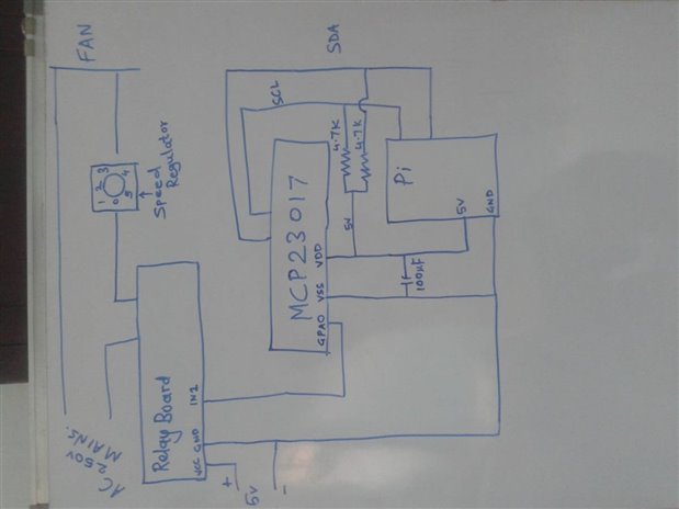
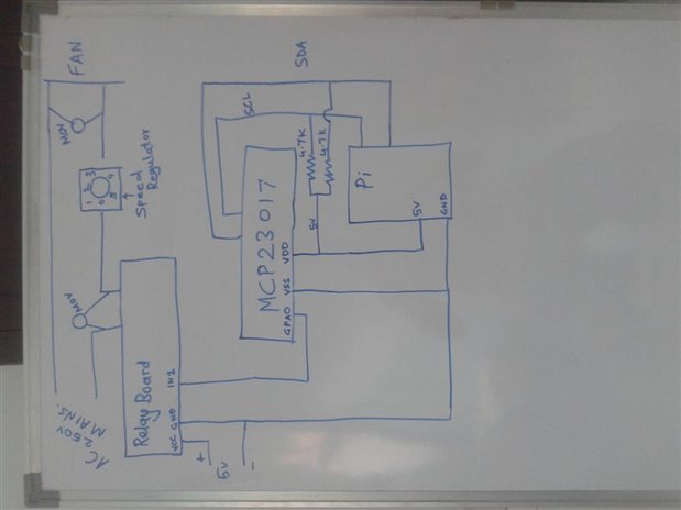
I have attached AC fan as load to my SainSmart 8 Channel DC 5V Relay Module.

The relay board is supplied with external power supply(5V,1Amp).The relay board is controlled by MCP23017(gpio expander ic connected to my raspberry pi).

The fan is with Regulator.Sometimes when i change speed from regulator the ic is reset and relays stop working.

  • Sign in to reply
  • Cancel
  • mcb1
    0 mcb1 over 10 years ago in reply to Former Member

    Nilay

    Have you added pullup resistors on the SCL and SDA lines to 3v3 as I mentioned earlier.?


    A 275v MOV is primary designed to conduct when the voltage exceeds 275v AC and IMO won't fix spikes when the contact opens.

    I doubt that an induction motor fan will generate enough energy to be causing it, it will be the 5v relays.

    The question is does it happen when you don't have the fan connected.?

    What happens if you switch the mains off, but leave the fan connected.?


    If you could mark the capacitors on your drawing and repost, we might be able to see if there is something overlooked.

    You have shown a ground connection running from the RPi ground and the power supply. Is this actually connected to anything or is just a symbol.?


    Mark

    • Cancel
    • Vote Up 0 Vote Down
    • Sign in to reply
    • Verify Answer
    • Cancel
  • michaelkellett
    0 michaelkellett over 10 years ago in reply to mcb1

    The MOV shouldn't be connected across the relay contacts but across the load.


    Definitely do the experiment with the fan removed (but I think we have established that the problem only happens with the fan and that lamps are OK).


    And you must add those pull up resistors.


    How about a full circuit and some pictures - it's often hard to fix this kind of issue when the device is on the bench in front of you - it's really hard to pin it down at long distance.


    MK

    • Cancel
    • Vote Up 0 Vote Down
    • Sign in to reply
    • Verify Answer
    • Cancel
  • Former Member
    0 Former Member over 10 years ago

    1st image is the circuit with capacitor across vdd and vss which is succesfull in protecting the spikes ( reducing enough to not reset the mcp).

    2nd image is when i tried the mov across the load as well as across the relay contacts later. both places mov failed to protect from spikes and eventually reset.imageimage

    .

    • Cancel
    • Vote Up 0 Vote Down
    • Sign in to reply
    • Verify Answer
    • Cancel
  • michaelkellett
    0 michaelkellett over 10 years ago in reply to Former Member

    Is it always OK with the 100uF capacitor in place ?


    MK

    • Cancel
    • Vote Up 0 Vote Down
    • Sign in to reply
    • Verify Answer
    • Cancel
  • Former Member
    0 Former Member over 10 years ago in reply to michaelkellett

    yes it is always ok with the capacitor. i have tried it rigorously to ensure that.

    • Cancel
    • Vote Up 0 Vote Down
    • Sign in to reply
    • Verify Answer
    • Cancel
  • michaelkellett
    0 michaelkellett over 10 years ago in reply to Former Member

    So that sounds like the problem is solved -  I can't understand why the fan was worse than the lamps - but I don't think you need care too much if it's working now.


    MK

    • Cancel
    • Vote Up 0 Vote Down
    • Sign in to reply
    • Verify Answer
    • Cancel
  • Former Member
    0 Former Member over 10 years ago in reply to michaelkellett

    yes sir its working with capacitor. but i wonder why not with mov.. as that would have further directly protected relay from spikes fairly. 

    • Cancel
    • Vote Up 0 Vote Down
    • Sign in to reply
    • Verify Answer
    • Cancel
  • rew
    0 rew over 10 years ago in reply to Former Member

    When a chip "suddenly" needs a bigger current it takes a while before the power supply can react and provide such a bigger current. (Electronics engineers call it wire inductance).


    When you don't have a capacitor near your chip, the voltage near the chip might drop to such a level that either the chip malfunctions or the chip performs a power-on-reset. This is what you were seeing.


    So, now you have a capacitor near your chip, the sudden currents can be drawn partly and temporarily from the capacitor so that neither a malfunction or a reset happens.

    • Cancel
    • Vote Up 0 Vote Down
    • Sign in to reply
    • Verify Answer
    • Cancel
  • mcb1
    0 mcb1 over 10 years ago in reply to Former Member

    Nilay

    The SCL and SDA pullup resitors need to go to the 3v3 supply as the RPi is a 3v3 device NOT 5v.

    http://www.raspberrypi.org/documentation/usage/gpio/

    http://elinux.org/RPi_Low-level_peripherals


    Thats the entire reason you have the MCP23017 in the circuit.


    Mark

    • Cancel
    • Vote Up 0 Vote Down
    • Sign in to reply
    • Verify Answer
    • Cancel
  • rew
    0 rew over 10 years ago in reply to mcb1

    Well..... it is debatable weather they are required/allowed/not allowed.


    In practise the 3.3V signals from the raspberry pi will reliably read as "high" on all my 5V devices. So IMHO that rules out "required".


    With the 4k7 pullups in parallel with the 1.8k pull-to-3.3V resistors on the effect is a 1.3k pullup to 3.8V. This makes the "high" level slightly easier to detect (a bit more margin) than without the pullup, while still within 0.5V from the 3.3V of the 'pi. Going any higher will cause a current to flow through a protection diode INTO the 3.3V line of the broadcom. Those diodes are designed to withstand a short current pulse, but not a continuous current. On the other hand, they don't explode the second you use them. They are designed to protect the chip! So limiting the current to 1mA will keep the diode in one piece. So IMHO, this rules out "not allowed".


    Oh, and putting the pullups to the 3.3V is completely useless, as the raspberry pi already has pullup resistors on the board. So that would just lower the pullup resistor value a bit. The foundation decided 1.8k was a good value, so why change that?


    I personally would try the simpler circuit without those resistors.


    On the other hand, I sell proper level shifters if you want: I2C Level Shifter.

    Or you can get it integrated in the small breakout board that we sell to get a "neat" 4pin I2C connector: Raspberry Pi Serial BoB (this one also breaks out the SPI and UART busses).

    • Cancel
    • Vote Up +1 Vote Down
    • Sign in to reply
    • Verify Answer
    • Cancel
<>
element14 Community

element14 is the first online community specifically for engineers. Connect with your peers and get expert answers to your questions.

  • Members
  • Learn
  • Technologies
  • Challenges & Projects
  • Products
  • Store
  • About Us
  • Feedback & Support
  • FAQs
  • Terms of Use
  • Privacy Policy
  • Legal and Copyright Notices
  • Sitemap
  • Cookies

An Avnet Company © 2025 Premier Farnell Limited. All Rights Reserved.

Premier Farnell Ltd, registered in England and Wales (no 00876412), registered office: Farnell House, Forge Lane, Leeds LS12 2NE.

ICP 备案号 10220084.

Follow element14

  • X
  • Facebook
  • linkedin
  • YouTube