element14 Community
element14 Community
    Register Log In
  • Site
  • Search
  • Log In Register
  • About Us
  • Community Hub
    Community Hub
    • What's New on element14
    • Feedback and Support
    • Benefits of Membership
    • Personal Blogs
    • Members Area
    • Achievement Levels
  • Learn
    Learn
    • Ask an Expert
    • eBooks
    • element14 presents
    • Learning Center
    • Tech Spotlight
    • STEM Academy
    • Webinars, Training and Events
    • Learning Groups
  • Technologies
    Technologies
    • 3D Printing
    • FPGA
    • Industrial Automation
    • Internet of Things
    • Power & Energy
    • Sensors
    • Technology Groups
  • Challenges & Projects
    Challenges & Projects
    • Design Challenges
    • element14 presents Projects
    • Project14
    • Arduino Projects
    • Raspberry Pi Projects
    • Project Groups
  • Products
    Products
    • Arduino
    • Avnet Boards Community
    • Dev Tools
    • Manufacturers
    • Multicomp Pro
    • Product Groups
    • Raspberry Pi
    • RoadTests & Reviews
  • Store
    Store
    • Visit Your Store
    • Choose another store...
      • Europe
      •  Austria (German)
      •  Belgium (Dutch, French)
      •  Bulgaria (Bulgarian)
      •  Czech Republic (Czech)
      •  Denmark (Danish)
      •  Estonia (Estonian)
      •  Finland (Finnish)
      •  France (French)
      •  Germany (German)
      •  Hungary (Hungarian)
      •  Ireland
      •  Israel
      •  Italy (Italian)
      •  Latvia (Latvian)
      •  
      •  Lithuania (Lithuanian)
      •  Netherlands (Dutch)
      •  Norway (Norwegian)
      •  Poland (Polish)
      •  Portugal (Portuguese)
      •  Romania (Romanian)
      •  Russia (Russian)
      •  Slovakia (Slovak)
      •  Slovenia (Slovenian)
      •  Spain (Spanish)
      •  Sweden (Swedish)
      •  Switzerland(German, French)
      •  Turkey (Turkish)
      •  United Kingdom
      • Asia Pacific
      •  Australia
      •  China
      •  Hong Kong
      •  India
      •  Korea (Korean)
      •  Malaysia
      •  New Zealand
      •  Philippines
      •  Singapore
      •  Taiwan
      •  Thailand (Thai)
      • Americas
      •  Brazil (Portuguese)
      •  Canada
      •  Mexico (Spanish)
      •  United States
      Can't find the country/region you're looking for? Visit our export site or find a local distributor.
  • Translate
  • Profile
  • Settings
Raspberry Pi
  • Products
  • More
Raspberry Pi
Raspberry Pi Forum RPI Pico & ST7789 Display
  • Blog
  • Forum
  • Documents
  • Quiz
  • Events
  • Polls
  • Files
  • Members
  • Mentions
  • Sub-Groups
  • Tags
  • More
  • Cancel
  • New
Join Raspberry Pi to participate - click to join for free!
Featured Articles
Announcing Pi
Technical Specifications
Raspberry Pi FAQs
Win a Pi
Raspberry Pi Wishlist
Actions
  • Share
  • More
  • Cancel
Forum Thread Details
  • Replies 15 replies
  • Subscribers 661 subscribers
  • Views 15907 views
  • Users 0 members are here
  • st7789
  • rpi pico
Related

RPI Pico & ST7789 Display

scottiebabe
scottiebabe over 3 years ago

I purchased an off brand ST7789 1.3" Display a few months ago and recently decided it was time to try it out.


I did not realize it at the time but there isn't a consistent pinout between display boards. As it turns out the board I purchased did not pin out the chip-select (CS) line.


The ST7789 display driver will function without a CS line, however you need to configure the SPI mode (idle state, edge polarity) to communicate with the display. In most cases, I suppose that would be easy enough to change the display driver.


Now I wanted to make use of this display with a PI Pico and Micropython. Pimoroni provide a Micropython release with a small number additional libraries on top of MicroPython : https://github.com/pimoroni/pimoroni-pico (unlike CircuitPython which is significantly different from MicroPython).


I was trying to get their example code for one of their displays: https://shop.pimoroni.com/products/1-3-spi-colour-lcd-240x240-breakout to function with my off brand display. Unfortunately, I could not find a way to change the SPI operating mode of the display driver unless I wanted to compile their distribution from source (which I didn't want to do), the SPI initialization was all buried in C code.


An intsructables author provided a wonderful guide to breaking out the chip-select line: https://www.instructables.com/Adding-CS-Pin-to-13-LCD/  Many thanks. In the process of modify my display I learned a few things the hard way:

  • Rotated R1 90' to bypass the NPN switch
  • Tossed R2 away and used this as the CS pad
  • Be carful with getting the display too hot. The adhesive that held the display in place virtually no longer exists now image
  • Be carful cleaning! Or don't clean at all. I ended up relocating the flux residue with isopropyl from the PCB to inside the display housing and its now a little merky image

image


After the display modifications the display came to life!


You don't have permission to edit metadata of this video.
Edit media
x
image
Upload Preview
image


I have never used one of these displays before, but I have to say I am impressed. I was able to get 35 FPS out of a 240x240 display running over SPI.


I still don't know what the best way to add graphics to the PICO is. The image I showed in the video was created with ffmpeg outputting a raw video frame:


ffmpeg -vcodec png -i img.png -vcodec rawvideo -f rawvideo -pix_fmt rgb565 img.raw


Of this random image cropped down to 240x240:

image

Loading the image from flash was very slow.


Update: Image Loading Speed

The framebuffer for the ST7789 is stored big-endian so when I was loading the Image I had endian swap in python which was really slow. I can endian swap the raw image file format using dd:

dd conv=swab if=img.raw of=img2.raw

Now loading the image is now significantly faster:

t1 = time.ticks_us()
with open('img2.raw', 'rb') as f:
    for j in range(0,240,24):
        display_buffer[480*j:(480*(j+24))] = f.read(240*48)

display.update() # only update display once now, remove those tabs!
print((time.ticks_us() - t1)/1000)


Which now runs in 232 ms 85 ms and appears more as a transition animation versus terribly slow code.


Update: Overclocking in MicroPython

One can adjust the system clock frequency in MicroPython by issuing the following command:

machine.freq(190_000_000) # set system clock in Hz


When MicroPython alters the system clock frequency, it also reconfigures the peripheral clock source from clk_sys to the external crystal oscillator.

image


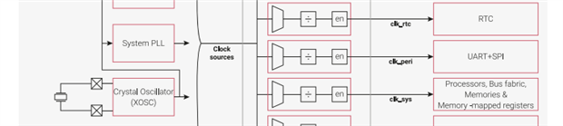
So, if you want to maintain a high-speed SPI clock frequency, you need to set the clock mux back to clk_sys yourself by:

mem32[0x40008000+0x48] = 0x800


With the Pico running at 190 MHz I achieved the following:

     Rainbow Spinner: 53 FPS

     FFT Demo: 16 FPS

     Image Load + Draw: 56 ms (49ms letting the garbage collector run before the load)


Of course, there are no guarantees this will always work for every Pico and or display.

  • Sign in to reply
  • Cancel
  • shabaz
    shabaz over 3 years ago

    Hi Scott,


    Great results! That is impressive performance. They are nice displays, I tried the same model (identical board to yours)  a while back, but with Arduino. However there the SPI code worked without the chip-select (I probably assigned the chip-select to an unused pin, I'd have to check).

    Looks like you're experiencing situations in Python not unlike what I'm experiencing - I'm currently trying to drive a chip which comes with a library on CircuitPython, but it's not a very good library, and I too don't want to compile from source, it defeats the purpose for me because I don't want to maintain the C code for this particular project, so I've had to re-write, but most code out there for microcontrollers is in C, so just porting code becomes quite an effort if it needs converting to Python.

    I kind-of got it working but there's enough of a discrepancy that I now have to compile in C anyway (I will stub out stuff and compile to run on my PC), so I can compare the two! So, double the work, although the ultimate aim was to make it simpler for the end-user who can then modify the Python code more easily than the C code.


    Regarding graphics, when I tried that display, since I was coding in C, I used a C array and it became a permanent part of the executable, not ideal admittedly but then I didn't need a file system etc. I probably used an online tool to convert from (say) .bmp to the C array, but I can't recall for sure now. I guess it could be possible to have a Python list but it might be inefficient (no idea).

    • Cancel
    • Vote Up 0 Vote Down
    • Sign in to reply
    • Cancel
  • scottiebabe
    scottiebabe over 3 years ago

    Color Fading Demo with 35 FPS

    Micropython Release: MicroPython with Pimoroni Libs (1010KB) - https://github.com/pimoroni/pimoroni-pico/releases/download/v0.2.7/pimoroni-pico-v0.2.7-micropython-v1.16.uf2


    Was derived from 2 Pimoroni sample python applications:

    https://github.com/pimoroni/pimoroni-pico/blob/main/micropython/examples/breakout_colourlcd240x240/demo.py

    https://github.com/pimoroni/pimoroni-pico/blob/main/micropython/examples/pico_display/rainbow.py


    The only notable changes I had to make were:

    • Configure a GPIO for the reset input of my display (active-low). RST must be set high to run.
    • After display initialization I modified the SPI0 clock speed to Fsys/2


    from machine import Pin, SPI, mem32
    import time
    import random
    import math
    from breakout_colourlcd240x240 import BreakoutColourLCD240x240
    
    rst = Pin(13,Pin.OUT)
    rst.value(1)
    
    width = BreakoutColourLCD240x240.WIDTH
    height = BreakoutColourLCD240x240.HEIGHT
    
    display_buffer = bytearray(width * height * 2)  # 2-bytes per pixel (RGB565)
    display = BreakoutColourLCD240x240(display_buffer)
    
    mem32[0x4003c000] = 0x007 # Configure SPI0 CLKFREQ for Fsys/2
    
    # Load Image from flash memory
    # Size is know to be 240x240 
    t1 = time.ticks_us()
    with open('img2.raw', 'rb') as f:
        for j in range(0,240,24):
            display_buffer[480*j:(480*(j+24))] = f.read(240*48)
            display.update()
    print((time.ticks_us() - t1)/1000)
    
    time.sleep(3)
    
    # From CPython Lib/colorsys.py
    def hsv_to_rgb(h, s, v):
        if s == 0.0:
            return v, v, v
        i = int(h * 6.0)
        f = (h * 6.0) - i
        p = v * (1.0 - s)
        q = v * (1.0 - s * f)
        t = v * (1.0 - s * (1.0 - f))
        i = i % 6
        if i == 0:
            return v, t, p
        if i == 1:
            return q, v, p
        if i == 2:
            return p, v, t
        if i == 3:
            return p, q, v
        if i == 4:
            return t, p, v
        if i == 5:
            return v, p, q
    
    h = 0
    t1 = time.ticks_us()
    fps=float('nan')
    phi=0
    while True:
        # run 30 frames before taking a timestamp
        for i in range(30):
            h += 3.7
            r, g, b = [int(255 * c) for c in hsv_to_rgb(h / 360.0, 1.0, 1.0)]  # rainbow magic
            display.set_pen(r, g, b)  # Set pen to a converted HSV value
            display.clear()           # Fill the screen with the colour
            display.set_pen(0, 0, 0)  # Set pen to black
            display.text("Scottie", 10, 10, 240, 6)  # Add some text
            display.text("FPS: {:1.1f}".format(fps), 10, 50, 240, 6)  # Add some text
            display.set_pen(0, 0, 0)  # Set pen to black
            phi = phi + math.pi/32 % 2*math.pi
            xp = int(120 + 40*math.sin(phi))
            yp = int(150 + 40*math.cos(phi))
            display.circle(xp,yp,4)
            xp = int(120 + 40*math.sin(phi+math.pi))
            yp = int(150 + 40*math.cos(phi+math.pi))
            display.circle(xp,yp,4)
            tm = time.localtime()
            display.text("{:02d}:{:02d}:{:02d}".format(tm[3],tm[4],tm[5]), 10, 220, 240, 3)  # Add some text
            display.update()          # Update the display
            
        fps = 30/(time.ticks_us()-t1)*1e6
        t1 = time.ticks_us()

    • Cancel
    • Vote Up 0 Vote Down
    • Sign in to reply
    • Cancel
  • scottiebabe
    scottiebabe over 3 years ago

    FFT Display Demo: FPS ~ 10


    Micropython Release: MicroPython with Pimoroni Libs (1010KB) - https://github.com/pimoroni/pimoroni-pico/releases/download/v0.2.7/pimoroni-pico-v0.2.7-micropython-v1.16.uf2

    With Inspiration from: https://github.com/pimoroni/pimoroni-pico/blob/main/micropython/examples/breakout_colourlcd240x240/demo.py


    This is just a quick lash-up to try out the NumPy (ulab) implementation on a RPI Pico. Considering most of these calculations are done as single precision floats on a processor with no floating point support and in python, the results are reasonable enough.


    from machine import Pin, SPI, mem32
    import time
    import random
    import math
    from ulab import numpy as np
    from random import random as randf
    from breakout_colourlcd240x240 import BreakoutColourLCD240x240
    np.set_printoptions(threshold=1000)
    
    rst = Pin(13,Pin.OUT)
    rst.value(1)
    
    width = BreakoutColourLCD240x240.WIDTH
    height = BreakoutColourLCD240x240.HEIGHT
    
    display_buffer = bytearray(width * height * 2)  # 2-bytes per pixel (RGB565)
    display = BreakoutColourLCD240x240(display_buffer)
    display.set_pen(255, 255, 255)  # Set pen to white
    display.clear()           # Fill the screen with the colour
    mem32[0x4003c000] = 0x007
    
    N = 256 # FFT Length
    
    # Synthesize Hanning FFT Window
    win = 0.5*(1 - np.cos(2*math.pi*np.array(range(1,N+1))/(N+1)))
    W = np.fft.fft(win)
    Wgain = sum((W[0]**2 + W[1]**2))/N**2;
    del(W)
    
    def RandWinFTT(Omega):
        noise = np.array([ randf() for i in range(N) ] )
        sig = np.array([ 10*math.sin(i*Omega) for i in range(N) ])
        yy = sig + noise
        yy = yy * win
        YY = np.fft.fft(yy)
    
        YMag = ((YY[0]**2 + YY[1]**2)**(1/2))*2/N/Wgain
        YMagdB = 20*np.log10(YMag)
        
        return np.array(YMagdB[0:int(N/2+1)],dtype=np.int8)
    
    t1 = time.ticks_us()
    fps=float('nan')
    i = 0
    while True:
        display.set_pen(255, 194, 232)  # Set pen to white
        display.clear()           # Fill the screen with the colour
        display.set_pen(0, 0, 0)  # Set pen to black
        display.text("FFT 256", 10, 10, 240, 6)  # Add some text
        display.text("FPS: {:1.1f}".format(fps), 10, 50, 240, 6)  # Add some text
        
        d = random.uniform(1,128)
        Y = RandWinFTT(math.pi*d/128)
        display.set_pen(0, 0, 0)  # Set pen to black
        xo = 50
        yo = 200
        
        idxmin = Y < -40.0; Y[idxmin] = -40.0
        idxmax = Y > 30.0; Y[idxmax] = 30.0
        Ys = Y  + 40.0
        for x in range(128):
            h = int(Ys[x])
            if h > 71:
                raise Exception('How!?')
            display.rectangle(xo+x,200-h,1,h)
            
        tm = time.localtime()
        display.text("{:02d}:{:02d}:{:02d}".format(tm[3],tm[4],tm[5]), 10, 220, 240, 3)  # Display Time
        display.text('Scottie',160,225,240,2)
        display.update()          # Update the display
        
        if i == 0:
            fps = 10/(time.ticks_us()-t1)*1e6
            t1 = time.ticks_us()
        i = (i+1) % 10


    There is some funny business with array indexing, sometimes the assignment doesn't take. Not sure if that's me or ulab.

    • Cancel
    • Vote Up 0 Vote Down
    • Sign in to reply
    • Cancel
  • scottiebabe
    scottiebabe over 3 years ago

    Pimoroni Thermometer Demo


    Original source code: https://github.com/pimoroni/pimoroni-pico/blob/main/micropython/examples/pico_display/thermometer.py


    I modified this sample application to run on a 240x240 display. This really only involved creating a display object from the 240x240 driver class. I also removed the sleep statement for the demo to run as fast as possible.

    You don't have permission to edit metadata of this video.
    Edit media
    x
    image
    Upload Preview
    image

    Sorry I bumped the board slightly out of focus. This is another neat example of what kind of performance you might see using uPython for graphics on a Pico.


    The modified code I used:

    # This example takes the temperature from the Pico's onboard temperature sensor, and displays it on Pico Display Pack, along with a little pixelly graph.
    # It's based on the thermometer example in the "Getting Started with MicroPython on the Raspberry Pi Pico" book, which is a great read if you're a beginner!
    
    from machine import Pin
    import utime
    import gc
    from breakout_colourlcd240x240 import BreakoutColourLCD240x240
    
    rst = Pin(13,Pin.OUT)
    rst.value(1)
    
    width = BreakoutColourLCD240x240.WIDTH
    height = BreakoutColourLCD240x240.HEIGHT
    
    display_buffer = bytearray(width * height * 2)  # 2-bytes per pixel (RGB565)
    display = BreakoutColourLCD240x240(display_buffer)
    
    # reads from Pico's temp sensor and converts it into a more manageable number
    sensor_temp = machine.ADC(4)
    conversion_factor = 3.3 / (65535)
    temp_min = 25
    temp_max = 60
    bar_width = 5
    
    # Set the display backlight to 50%
    display.set_backlight(0.5)
    
    temperatures = []
    
    colors = [(0, 0, 255), (0, 255, 0), (255, 255, 0), (255, 0, 0)]
    
    def temperature_to_color(temp):
        temp = min(temp, temp_max)
        temp = max(temp, temp_min)
    
        f_index = float(temp - temp_min) / float(temp_max - temp_min)
        f_index *= len(colors) - 1
        index = int(f_index)
    
        if index == len(colors) - 1:
            return colors[index]
    
        blend_b = f_index - index
        blend_a = 1.0 - blend_b
    
        a = colors[index]
        b = colors[index + 1]
    
        return [int((a[i] * blend_a) + (b[i] * blend_b)) for i in range(3)]
    
    while True:
        # fills the screen with black
        display.set_pen(0, 0, 0)
        display.clear()
    
        # the following two lines do some maths to convert the number from the temp sensor into celsius
        reading = sensor_temp.read_u16() * conversion_factor
        temperature = 27 - (reading - 0.706) / 0.001721
    
        temperatures.append(temperature)
    
        # shifts the temperatures history to the left by one sample
        if len(temperatures) > width // bar_width:
            temperatures.pop(0)
    
        i = 0
        for t in temperatures:
            # chooses a pen colour based on the temperature
            display.set_pen(*temperature_to_color(t))
    
            # draws the reading as a tall, thin rectangle
            display.rectangle(i, height - ((round(t)-20) * 4), bar_width, height)
    
            # the next tall thin rectangle needs to be drawn
            # "bar_width" (default: 5) pixels to the right of the last one
            i += bar_width
    
        # draws a white background for the text
        display.set_pen(255, 255, 255)
        display.rectangle(1, 1, 100, 25)
    
        # writes the reading as text in the white rectangle
        display.set_pen(0, 0, 0)
        display.text("{:.2f}".format(temperature) + "c", 3, 3, 0, 3)
    
        # time to update the display
        display.update()
    
        # Run Full Speed!

    • Cancel
    • Vote Up 0 Vote Down
    • Sign in to reply
    • Cancel
  • scottiebabe
    scottiebabe over 3 years ago in reply to shabaz

    I would absolutely agree I am having a similar experience with uPython. It has been extremely easy to do the things that already work and are well documented and tested. However for any task that is not supported out of the box Its a bit of a mixed bag.


    Graphics:

    I'm not sure why the framebuffer is endian-swaped, that could have been done in a PIO SM, however its free code that does work so I can't really complain.


    I though maybe I could draw a screen template in inkscape and load that as a base canvas into the framebuffer and then overlay some basic text as needed. However I can't allocate 2 display buffers of 240x240x2 bytes in uPython. The Pico has the memory, so in C I would have been able to do this. But now that I have pre endian swaped the image the load time is quick enough, I think.


    Still all things consider this is pretty amazing. These are really are beautiful little displays even with some flux residue in it image.

    • Cancel
    • Vote Up 0 Vote Down
    • Sign in to reply
    • Cancel
  • scottiebabe
    scottiebabe over 3 years ago

    Lorenez Clock

    For how complicated the mathematics are describing this particular set of differential equations, the MicroPython code to numerically solve the ODE is quite simple.


    https://en.wikipedia.org/wiki/Lorenz_system


    You don't have permission to edit metadata of this video.
    Edit media
    x
    image
    Upload Preview
    image


    from machine import Pin, SPI, mem32
    import time
    import random
    import math
    from ulab import numpy as np
    from random import random as randf
    from breakout_colourlcd240x240 import BreakoutColourLCD240x240
    np.set_printoptions(threshold=1000)
    
    rst = Pin(13,Pin.OUT)
    rst.value(1)
    
    width = BreakoutColourLCD240x240.WIDTH
    height = BreakoutColourLCD240x240.HEIGHT
    
    display_buffer = bytearray(width * height * 2)  # 2-bytes per pixel (RGB565)
    display = BreakoutColourLCD240x240(display_buffer)
    display.set_pen(255, 255, 255)  # Set pen to white
    display.clear()           # Fill the screen with the colour
    mem32[0x4003c000] = 0x007 # Configure SPI0 CLKFREQ for Fsys/2
    
    # From CPython Lib/colorsys.py
    def hsv_to_rgb(h, s, v):
        if s == 0.0:
            return v, v, v
        i = int(h * 6.0)
        f = (h * 6.0) - i
        p = v * (1.0 - s)
        q = v * (1.0 - s * f)
        t = v * (1.0 - s * (1.0 - f))
        i = i % 6
        if i == 0:
            return v, t, p
        if i == 1:
            return q, v, p
        if i == 2:
            return p, v, t
        if i == 3:
            return p, q, v
        if i == 4:
            return t, p, v
        if i == 5:
            return v, p, q
    
    # Lorenz State Model from Wikipedia
    # https://en.wikipedia.org/wiki/Lorenz_system#Python_simulation
    rho = 28.0
    sigma = 10.0
    beta = 8.0 / 3.0
    
    def f(state, t):
        x, y, z = state  # Unpack the state vector
        return np.array([sigma * (y - x), x * (rho - z) - y, x * y - beta * z])  # Derivatives
    
    state0 = np.array([1.0, 1.0, 1.0])
    state = state0
    
    display.set_pen(0, 0, 0)  # Set pen to black
    display.clear()           # Fill the screen with the colour
    
    xo = 120
    yo = 40
    tscreen = time.time() # time of last screen clear
    h=0 # hue angle
    while True:
        h += 1
        r, g, b = [int(255 * c) for c in hsv_to_rgb(h / 360.0, 1.0, 1.0)] 
        display.set_pen(r, g, b)  # Set pen to a converted HSV value
        
        for i in range(10):
            state = state + f(state,0)/1e3
            
        display.circle(int(xo+4*state[0]),int(yo+4*state[2]),1)
            
        display.set_pen(0, 0, 0)
        display.rectangle(50,0,200,50)
        display.set_pen(255, 255, 255)
        tm = time.localtime()
        display.text("{:02d}:{:02d}:{:02d}".format(tm[3],tm[4],tm[5]), 35, 0, 240, 5)  # Display Time
        display.text('Scottie',160,225,240,2)
        display.update()          # Update the display
        
        # clear screen every 2 minutes
        if time.time() - tscreen > 120:
            tscreen = time.time()
            display.set_pen(0, 0, 0)
            display.clear()


    I might look into implementing an actual ODE solver, but for now the solution it creates appear quite elegant (regardless if they may not be accurate).


    Still kind of amazed how simple that was to implement when using the demo examples as a starting point.


    This might be a project that deserves a real enclosure.

    • Cancel
    • Vote Up 0 Vote Down
    • Sign in to reply
    • Cancel
  • shabaz
    shabaz over 3 years ago in reply to scottiebabe

    Nice project, and actually an excellent example showing the power of Python versus (say) C. It's so much easier to do all the maths algorithms in Python. Sure it won't run as fast as optimised C code, but efficiency of personal time use getting projects out of the door, or the ability to rapidly modify algorithms, may be more important than raw performance during execution.

    I wonder, has anyone implemented a pocket calculator or pocket computer with Pi Pico yet? I'd have thought that was a project screaming out for someone to implement.

    • Cancel
    • Vote Up 0 Vote Down
    • Sign in to reply
    • Cancel
  • scottiebabe
    scottiebabe over 3 years ago in reply to shabaz

    Thank you for the kind words. I'm not sure if anyone has but together a pico calculator yet, with python it would be easy to support complex expressions. I have considered playing around with with a making a keypad layout for technical individuals not accountants. I still use my pocket scientific calculator all the time. Recently with micropython I have found myself holding a scope probe in one hand (or multimeter probe) and trying type with the other. I wish my keyboard keypad was had some of the same keys as my scientific calculator.


    From what I gather making a USB HID device is supposed to be simple with the Pico. Though, I have yet to try it myself.

    • Cancel
    • Vote Up 0 Vote Down
    • Sign in to reply
    • Cancel
  • shabaz
    shabaz over 3 years ago in reply to scottiebabe

    I learned a major problem with CircuitPython today; it is single-precision! I was hitting all manner of problems trying to do PLL configurations, and eventually realized it was due to that : ( I've not found out about MicroPython, but if it supports double precision on the Pico then I'm swapping over immediately : ) I've already hit two bugs with CircuitPython, one each on two separate releases, so CircuitPython is not giving me stability confidence either : ( originally I thought a benefit of CircuitPython would have been the vast amount of libraries, but of the few I tried, they all had limitations so I had to write my own code in place of the libraries : (

    • Cancel
    • Vote Up 0 Vote Down
    • Sign in to reply
    • Cancel
  • fmilburn
    fmilburn over 3 years ago in reply to shabaz

    I ran into the single-precision issue with CircuitPython also.  MicroPython can do double-precision floating and multi-precision integer but I haven't tried it yet: Maximum and minimum int and float values? - MicroPython Forum.  It can also do interrupts of some sort if I remember correctly and has experimental threads that haven't been implemented.

    • Cancel
    • Vote Up 0 Vote Down
    • Sign in to reply
    • Cancel
>
element14 Community

element14 is the first online community specifically for engineers. Connect with your peers and get expert answers to your questions.

  • Members
  • Learn
  • Technologies
  • Challenges & Projects
  • Products
  • Store
  • About Us
  • Feedback & Support
  • FAQs
  • Terms of Use
  • Privacy Policy
  • Legal and Copyright Notices
  • Sitemap
  • Cookies

An Avnet Company © 2025 Premier Farnell Limited. All Rights Reserved.

Premier Farnell Ltd, registered in England and Wales (no 00876412), registered office: Farnell House, Forge Lane, Leeds LS12 2NE.

ICP 备案号 10220084.

Follow element14

  • X
  • Facebook
  • linkedin
  • YouTube