element14 Community
element14 Community
    Register Log In
  • Site
  • Search
  • Log In Register
  • About Us
  • Community Hub
    Community Hub
    • What's New on element14
    • Feedback and Support
    • Benefits of Membership
    • Personal Blogs
    • Members Area
    • Achievement Levels
  • Learn
    Learn
    • Ask an Expert
    • eBooks
    • element14 presents
    • Learning Center
    • Tech Spotlight
    • STEM Academy
    • Webinars, Training and Events
    • Learning Groups
  • Technologies
    Technologies
    • 3D Printing
    • FPGA
    • Industrial Automation
    • Internet of Things
    • Power & Energy
    • Sensors
    • Technology Groups
  • Challenges & Projects
    Challenges & Projects
    • Design Challenges
    • element14 presents Projects
    • Project14
    • Arduino Projects
    • Raspberry Pi Projects
    • Project Groups
  • Products
    Products
    • Arduino
    • Avnet Boards Community
    • Dev Tools
    • Manufacturers
    • Multicomp Pro
    • Product Groups
    • Raspberry Pi
    • RoadTests & Reviews
  • Store
    Store
    • Visit Your Store
    • Choose another store...
      • Europe
      •  Austria (German)
      •  Belgium (Dutch, French)
      •  Bulgaria (Bulgarian)
      •  Czech Republic (Czech)
      •  Denmark (Danish)
      •  Estonia (Estonian)
      •  Finland (Finnish)
      •  France (French)
      •  Germany (German)
      •  Hungary (Hungarian)
      •  Ireland
      •  Israel
      •  Italy (Italian)
      •  Latvia (Latvian)
      •  
      •  Lithuania (Lithuanian)
      •  Netherlands (Dutch)
      •  Norway (Norwegian)
      •  Poland (Polish)
      •  Portugal (Portuguese)
      •  Romania (Romanian)
      •  Russia (Russian)
      •  Slovakia (Slovak)
      •  Slovenia (Slovenian)
      •  Spain (Spanish)
      •  Sweden (Swedish)
      •  Switzerland(German, French)
      •  Turkey (Turkish)
      •  United Kingdom
      • Asia Pacific
      •  Australia
      •  China
      •  Hong Kong
      •  India
      •  Korea (Korean)
      •  Malaysia
      •  New Zealand
      •  Philippines
      •  Singapore
      •  Taiwan
      •  Thailand (Thai)
      • Americas
      •  Brazil (Portuguese)
      •  Canada
      •  Mexico (Spanish)
      •  United States
      Can't find the country/region you're looking for? Visit our export site or find a local distributor.
  • Translate
  • Profile
  • Settings
Raspberry Pi
  • Products
  • More
Raspberry Pi
Raspberry Pi Forum New Pico W
  • Blog
  • Forum
  • Documents
  • Quiz
  • Events
  • Polls
  • Files
  • Members
  • Mentions
  • Sub-Groups
  • Tags
  • More
  • Cancel
  • New
Join Raspberry Pi to participate - click to join for free!
Featured Articles
Announcing Pi
Technical Specifications
Raspberry Pi FAQs
Win a Pi
Raspberry Pi Wishlist
Actions
  • Share
  • More
  • Cancel
Forum Thread Details
  • Replies 40 replies
  • Subscribers 660 subscribers
  • Views 8229 views
  • Users 0 members are here
Related

New Pico W

mp2100
mp2100 over 3 years ago

I guess I should have guessed what all that empty space on the original Raspberry Pi Pico board was for.  They put a WiFi 802.11N chip there. CYW43439 from Infineon. This will be a nice board for IoT.  And it's cheap.  $6.

https://www.raspberrypi.com/news/raspberry-pi-pico-w-your-6-iot-platform/

image

  • Sign in to reply
  • Cancel
  • ntewinkel
    ntewinkel over 3 years ago in reply to ralphjy
    ralphjy said:
    Good prices, but no BLE.

    Good catch on that. I feel that BLE will be pretty much expected for WiFi boards soon. At the least it makes provisioning so much easier, being able to maintain a connection with an app while attempting to connect to WiFi.

    • Cancel
    • Vote Up +1 Vote Down
    • Sign in to reply
    • Cancel
  • dougw
    dougw over 3 years ago in reply to ntewinkel

    The Pico pinout form factor seems to be catching on - there are already many accessory cards using it. A bit like the Feather "standard". Now we have the "PicoPinout standard"

    • Cancel
    • Vote Up +2 Vote Down
    • Sign in to reply
    • Cancel
  • ralphjy
    ralphjy over 3 years ago

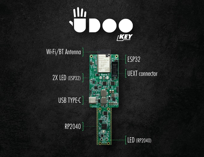
    Reminds me that I have a Kickstarter board that was supposed to deliver in January, but still has no new delivery date.  It's the UDOO Key which is basically an ESP32 dev board attached to a Pi Pico with added features like an IMU and digital microphone.  

    image

    I guess this board will be irrelevant when or if it ever shows up.  Can't believe they are trying to sell accessories for it...

    • Cancel
    • Vote Up +2 Vote Down
    • Sign in to reply
    • Cancel
  • ntewinkel
    ntewinkel over 3 years ago in reply to ralphjy

    That looks like it could still be a good board. the Grove integration and AI support might be just enough for them to get a following. They might have to lower the expected $20 price tag to something closer to $10-$15 to more generally compete with the others.

    I've seen a few other kickstarters lose ground due to delays too though - for example, the BuildOne $99 3d printer kickstarter was supposed to ship 5 years ago and it looks like it didn't make it. From what I can see, there are some starter 3d printers coming close to that price point now in general.

    • Cancel
    • Vote Up 0 Vote Down
    • Sign in to reply
    • Cancel
  • shabaz
    shabaz over 3 years ago in reply to cstanton

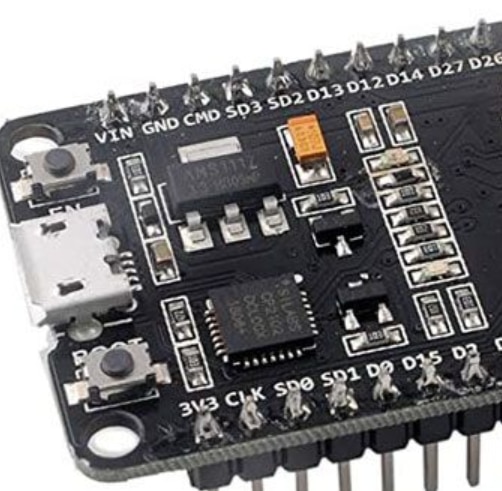
    There's a weird trend to locate components in rows etc, like this:

    image

    Not saying that's the cause (sometimes it's worse, this layout might be acceptable) but there isn't any technical reason for laying out the components like this, and that just makes me wonder if the design is suboptimal in other ways too. 

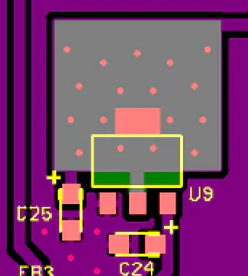
    I used the same LDO regulator as in the photo above for a project, but laid it out like this, no neat row of components, and a bit of heatsinking at least.

    image

    • Cancel
    • Vote Up 0 Vote Down
    • Sign in to reply
    • Cancel
  • cstanton
    cstanton over 3 years ago in reply to shabaz
    shabaz said:

    There's a weird trend to locate components in rows etc, like this:

    Either people really like orthogonal organisation, or it's faster for the pick and place machine when it's distributing multiple components of the same type close together.


    shabaz said:
    I used the same LDO regulator as in the photo above for a project, but laid it out like this, no neat row of components, and a bit of heatsinking at least.

    I'm no PCB designer, though I keep meaning to try, what do you tend to aim for when you're designing like this? cost or some other factors?

    • Cancel
    • Vote Up 0 Vote Down
    • Sign in to reply
    • Cancel
  • shabaz
    shabaz over 3 years ago in reply to cstanton

    Ah, that might be the reason, I believe some of the PnP machines have multiple heads to pick up more than one part for the same vicinity of the board as you say.

    Generally I'm trying to dimension the board and place connectors etc first, at nice millimetre positions, so that I can cut enclosures easier, and then roughly place the components where they are close to others in the same sub-circuit, and attempt to just route in the sub-circuit and then occasionally move some of the sub-circuits around on the board, sometimes change the schematic to make the routing easier (e.g. I almost always change connector pinouts, that's low-hanging fruit to make routing simpler), and then once it is all routed, personally I un-route and re-route in sections, rotating components and fine-positioning them at this point, because I can't get it done well in the first go. So for me, I end up routing things almost twice. I'm no PCB designer either, so I don't know if the experienced people manage to do it right in a more efficient way.

    With the ICs like the LDO regulator above, the datasheet is usually followed if it has guidelines or example layouts, or for more complex chips I'll take a look at the reference board for them. The decoupling capacitors I'll try to get one end of them (the positive end) as close to the pin on the IC as possible, and then make the other end go to ground through a couple of vias (the other side of the board is easiest if it's almost entirely ground). If I can't achieve an entire ground on the underside, then I'll aim for only short traces on the underside if possible.

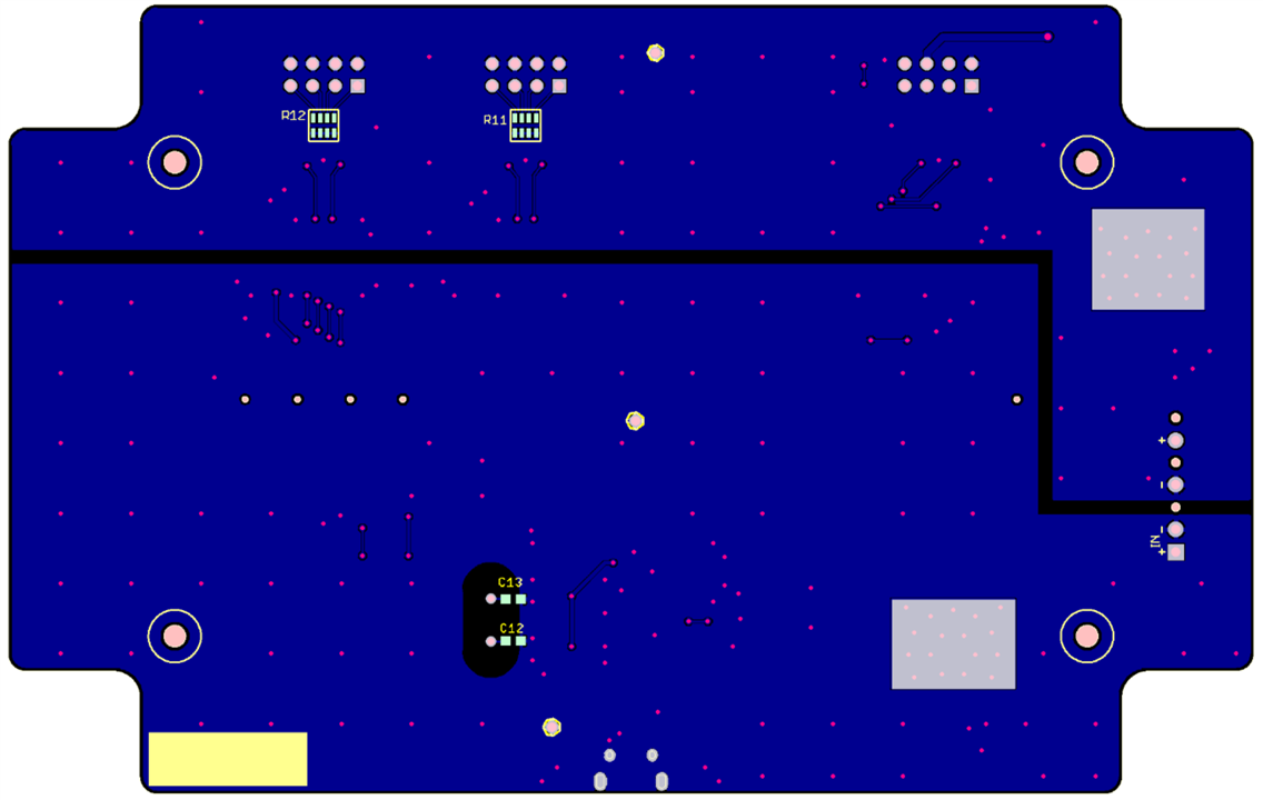
    For instance for the PCB in the example above, the underside looks like this (only very short traces where I couldn't manage to route on the top side): (The split is only because this board had an isolated ground side, that's not normally present on most boards):

    image 

    I rarely make things very compact, so I'm more likely to aim for a board that's possibly larger, and easy to work with and easy to fit in a standard case (I don't have the ability to do CAD enclosure design and 3D print). For some boards, I might not aim to fit into a case, but I'll put holes on the corners so that it can be (say) sandwiched between perspex sheets if needed.

    Also, I'll aim for placing extra components, like 0-ohm resistors, to join sub-circuits, in case I need to disconnect a portion while testing. I also won't try to cost-reduce by removing decoupling capacitors etc., since I'm not making anything in high volume (commercial products also don't always cost-reduce, for high-end products they will not try to reduce decoupling capacitors either, or pick the cheapest components, it's not worth the risk to product reliability, at least not unless there is a cost reduction exercise later during the product life-cycle). 

    • Cancel
    • Vote Up +1 Vote Down
    • Sign in to reply
    • Cancel
  • shabaz
    shabaz over 3 years ago in reply to cstanton

    Before microcontroller breakout or dev-boards were cheap : ) we would design our own boards each time we wanted to try a new processor. The manufacturer boards were too expensive unless you were 100% sure you were going to use the chip in a design, because the manufacturer board often had exotic in-circuit emulator on-board, and sometimes even fancy IC sockets for the target chip (even for surface-mount ICs - the sockets cost $$$) and the manufacturer dev board could cost thousands (today there are still dev-boards that cost thousands of course, but nowadays often they are for more high-end parts, sometimes lower volume devices).

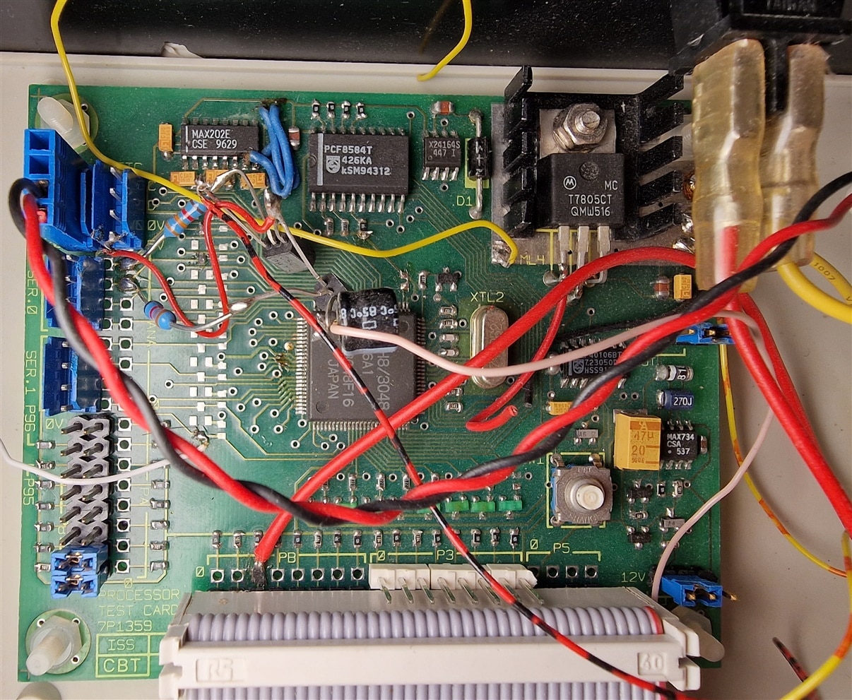
    Here's a dev-board for a Renesas/Hitachi processor, I designed the schematic (and as usual messed up the RS232 pin directions on the MAX202 chip, there are two blue bodge wires there : ) and just made sure to place some components that could be handy for testing or perhaps useful for the actual end product, but mostly just pin header connections. I also put LEDs onto eight or so pins (visible near the bottom of the board), to use as debug. I didn't do the PCB layout, that was done by a professional PCB designer.

    image

    • Cancel
    • Vote Up +3 Vote Down
    • Sign in to reply
    • Cancel
  • genebren
    genebren over 3 years ago in reply to shabaz

    I still build all of my own boards for my projects.  I write all of my code in bare metal style so that I can be absolutely sure that the software does what I want it to.

    Don't get me wrong, I do appreciate some of these amazing boards, but I just don't find them as easy to use and customize as I do building from scratch.

    There are times when I use a development board to test out a new processor (I think that I have bought 5 recently).

    • Cancel
    • Vote Up +3 Vote Down
    • Sign in to reply
    • Cancel
  • shabaz
    shabaz over 3 years ago

    One annoyance with the implementation is that the antenna will be buried in the middle of any enclosure that the Pico W is used in, because the micro USB connector will be on the side of the enclosure most likely, for access to it. That's assuming it's radiation pattern is say doughnut in the plane perpendicular to the Pico's plane along it's longest dimension.

    I guess there was nothing they could do since the shape of the Pico and the USB connector were fixed. It's hard retrofitting an antenna into the design when it wasn't originally designed for it I guess. Had they planned for it, they could have at least suggested in the user documentation of the original Pico, for people not to place a ground plane beneath the Pico at that end. Typical seat of the pants planning : (

    • Cancel
    • Vote Up +1 Vote Down
    • Sign in to reply
    • Cancel
<>
element14 Community

element14 is the first online community specifically for engineers. Connect with your peers and get expert answers to your questions.

  • Members
  • Learn
  • Technologies
  • Challenges & Projects
  • Products
  • Store
  • About Us
  • Feedback & Support
  • FAQs
  • Terms of Use
  • Privacy Policy
  • Legal and Copyright Notices
  • Sitemap
  • Cookies

An Avnet Company © 2025 Premier Farnell Limited. All Rights Reserved.

Premier Farnell Ltd, registered in England and Wales (no 00876412), registered office: Farnell House, Forge Lane, Leeds LS12 2NE.

ICP 备案号 10220084.

Follow element14

  • X
  • Facebook
  • linkedin
  • YouTube