element14 Community
element14 Community
    Register Log In
  • Site
  • Search
  • Log In Register
  • Community Hub
    Community Hub
    • What's New on element14
    • Feedback and Support
    • Benefits of Membership
    • Personal Blogs
    • Members Area
    • Achievement Levels
  • Learn
    Learn
    • Ask an Expert
    • eBooks
    • element14 presents
    • Learning Center
    • Tech Spotlight
    • STEM Academy
    • Webinars, Training and Events
    • Learning Groups
  • Technologies
    Technologies
    • 3D Printing
    • FPGA
    • Industrial Automation
    • Internet of Things
    • Power & Energy
    • Sensors
    • Technology Groups
  • Challenges & Projects
    Challenges & Projects
    • Design Challenges
    • element14 presents Projects
    • Project14
    • Arduino Projects
    • Raspberry Pi Projects
    • Project Groups
  • Products
    Products
    • Arduino
    • Avnet & Tria Boards Community
    • Dev Tools
    • Manufacturers
    • Multicomp Pro
    • Product Groups
    • Raspberry Pi
    • RoadTests & Reviews
  • About Us
    About the element14 Community
  • Store
    Store
    • Visit Your Store
    • Choose another store...
      • Europe
      •  Austria (German)
      •  Belgium (Dutch, French)
      •  Bulgaria (Bulgarian)
      •  Czech Republic (Czech)
      •  Denmark (Danish)
      •  Estonia (Estonian)
      •  Finland (Finnish)
      •  France (French)
      •  Germany (German)
      •  Hungary (Hungarian)
      •  Ireland
      •  Israel
      •  Italy (Italian)
      •  Latvia (Latvian)
      •  
      •  Lithuania (Lithuanian)
      •  Netherlands (Dutch)
      •  Norway (Norwegian)
      •  Poland (Polish)
      •  Portugal (Portuguese)
      •  Romania (Romanian)
      •  Russia (Russian)
      •  Slovakia (Slovak)
      •  Slovenia (Slovenian)
      •  Spain (Spanish)
      •  Sweden (Swedish)
      •  Switzerland(German, French)
      •  Turkey (Turkish)
      •  United Kingdom
      • Asia Pacific
      •  Australia
      •  China
      •  Hong Kong
      •  India
      •  Japan
      •  Korea (Korean)
      •  Malaysia
      •  New Zealand
      •  Philippines
      •  Singapore
      •  Taiwan
      •  Thailand (Thai)
      •  Vietnam
      • Americas
      •  Brazil (Portuguese)
      •  Canada
      •  Mexico (Spanish)
      •  United States
      Can't find the country/region you're looking for? Visit our export site or find a local distributor.
  • Translate
  • Profile
  • Settings
Raspberry Pi Projects
  • Products
  • Raspberry Pi
  • Raspberry Pi Projects
  • More
  • Cancel
Raspberry Pi Projects
Blog Making a Custom RP2040 Project with KiCad, Part 1!
  • Blog
  • Documents
  • Events
  • Polls
  • Members
  • Mentions
  • Sub-Groups
  • Tags
  • More
  • Cancel
  • New
Join Raspberry Pi Projects to participate - click to join for free!
  • Share
  • More
  • Cancel
Group Actions
  • Group RSS
  • More
  • Cancel
Engagement
  • Author Author: shabaz
  • Date Created: 24 Jun 2026 3:25 PM Date Created
  • Views 1304 views
  • Likes 9 likes
  • Comments 32 comments
  • kicad
  • pico
  • rpiexpert
  • rp2040
  • raspberry_pi_projects
  • pi pico
Related
Recommended

Making a Custom RP2040 Project with KiCad, Part 1!

shabaz
shabaz
24 Jun 2026

Partly out of curiosity, and partly to test some aspects of a workflow for other projects, I decided to create a custom RP2040 board. In most cases, there’s no need to do this; it may well be more expensive than simply using a ready-made Raspberry Pi Pico module and mounting it on a custom PCB, while saving a considerable amount of effort.

This short blog post describes how I’m approaching the project. It’s very much a work in progress.

The first thing I did was download the RP2040 hardware design guide PDF, and the minimal RP2040 design KiCad zip file from the Raspberry Pi website and extract and open the design with KiCad 10. This is what the minimal schematic looks like (click to enlarge):

image

The corresponding PCB layout is shown below. My plan is to reuse parts of this design while adapting it to fit the shape and requirements of my own PCB:

image

By examining the minimal PCB layout, it was possible to see that nearly all traces were on the top layer, with just a few on the underside, leaving the majority of the bottom copper being a ground plane.

Next, I modified the schematic by removing the components I didn’t need and adding the functionality I wanted. For example, I removed the pin headers and the Micro-B USB connector, replacing the latter with a USB-C connector. I also added RS-485 circuitry to one of the UART ports, since the board is intended to function as an RS-485 adapter.

You’ll also notice a 10-pin connector that appears to be underutilised. That’s intentional. I plan to route several unused GPIO pins to that connector in case I need them later. I haven’t assigned specific GPIOs yet; I’ll wait until the connector has been placed on the PCB so that I can choose whichever pins are physically closest. Anything that makes trace routing a little easier is worth considering!

image

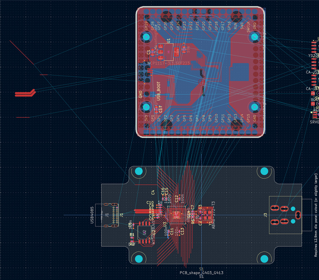
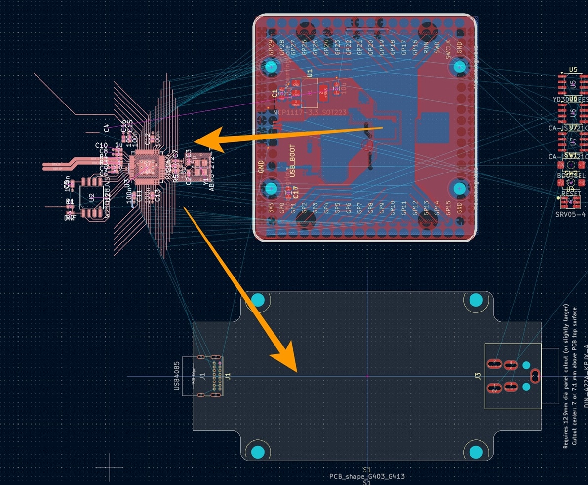
With the schematic updated, I switched to the PCB editor and took a screenshot of the original layout for reference. I then selected the main central portion of the circuitry and moved it onto my new PCB outline.
image

The result looked promising:

image

The original design includes a top-layer +3.3 V copper fill zone, and I wanted to preserve part of that arrangement. To do this, I simply created a new fill zone and roughly followed the outline of the original design, almost like connecting the dots.

image

Once that was done, I moved the new fill zone into its final position. In hindsight, it would have been easier to create the fill zone first and move it together with the rest of the circuitry, but it only took a few moments to fix. The layout was already starting to come together nicely.

image

Next, I selected the voltage regulator section from the original PCB and moved it into the desired location on the new board. Since I no longer needed any of the remaining elements from the original PCB layout, I deleted them. At this point, the project had effectively become a normal PCB design exercise, with the remaining tasks being component placement and trace routing.

image

I’ll write a Part 2 (EDIT: Here is part 2: (+) Getting Custom RP2040 Boards Produced and Assembled with KiCad, Part 2! - element14 Community ) once the layout is complete. I suspect it will be an even shorter post, since everything appears to be progressing smoothly so far.

Thanks for reading!

  • Sign in to reply

Top Comments

  • shabaz
    shabaz 1 month ago +2
    I wonder if the Raspberry Pi people every got one of these PCBs assembled.. they have traces not running through the center of pads. These are lightweight 0402 parts, they will rotate as the solder reflows…
  • arvindsa
    arvindsa 1 month ago +1
    I came here from your Part 2 of this post. Looking at the PCB Layout of the original PCB, I see a lot of polygon on top layer for the 3.3V Net. Now before I say something more, I have to say that I believe…
  • arvindsa
    arvindsa 1 month ago in reply to geralds +1
    I know that the pcb was from 3rd party. I put the question to Shabaz for his take on the originaldesign cos he would have studied the original design with more context. If RPi foundation made it for maker…
  • geralds
    geralds 1 month ago in reply to arvindsa

    Yes, I completely agree with you.

    I'm also curious to hear what Shabaz has to say about it.

    In the 2.part under Summary, he mentioned: "...whereas I skipped all that, considered a few basics (copper fill to avoid board warping and I tried to make the layout less likely ...."

    -->>>

    >> the top layer has the 3V3 polygon fulfilling the board, the 1V8 is just under the chip, the bot layer has the GND polygon fulfilling the board.

    I've been rereading the datasheets for the RP2040 and RP2350 controllers because of this project.

    The point the developers apparently also see is this, I belief:

    Heat generated by increasing the frequency/MHz. The higher the system frequency in the chip, the hotter it gets. The core can operate up to 200MHz, then it gets really hot.

    That's exactly what needs to be considered.

    I think that's what matters with Raspberry Pi.

    >> But --- the tracks from the GPIO's are very long and extrem diagonal routed. The components are very small, 402 for R and C and wide placed in the prairie.

    So, my view is: always pay attention to thermal issues (do we need a heat-sink, cooling fan, or no...), especially where speed and high-power consumption is involved.

    The deformation of the circuit board is definitely not good. This will cause a lot of problems with the traces, solder joints, components, etc. The more copper area there is, the more stable the circuit board is.

    • Cancel
    • Vote Up 0 Vote Down
    • Sign in to reply
    • More
    • Cancel
  • arvindsa
    arvindsa 1 month ago in reply to geralds

    I know that the pcb was from 3rd party.  I put the question to Shabaz for his take on the originaldesign cos he would have studied the original design with more context. If RPi foundation made it for maker community in mind, it would give an impression to makers that such complicated fills is needed. And might even intimidate them. 

    • Cancel
    • Vote Up +1 Vote Down
    • Sign in to reply
    • More
    • Cancel
  • geralds
    geralds 1 month ago in reply to arvindsa

    Hi  arvindsa 

    {"...can you think of any reason why these 3.3V copper fills exist?"...}

    This comes not from Shabaz, this comes from the original from RPI; please read the book https://pip-assets.raspberrypi.com/categories/814-rp2040/documents/RP-008279-DS-1-hardware-design-with-rp2040.pdf

    The RPI example created this lot of polygons. You're right, they are not needing. As well the 1V8 wire was created with a polygon, this is also, I would say, wrong.
    The point of the other hand is the temperature drain through the board. This is made with the GND pad. I think that this is enough. Or, but this pad you can make a bit larger.

    And no - we don't need an engineering bureau.Wink

    • Cancel
    • Vote Up 0 Vote Down
    • Sign in to reply
    • More
    • Cancel
  • arvindsa
    arvindsa 1 month ago

    I came here from your Part 2 of this post. Looking at the PCB Layout of the original PCB, I see a lot of polygon on top layer for the 3.3V Net. Now before I say something more, I have to say that I believe that when executing an engineering project, one has to design for the robustness for the intended purpose of the project. Anything beyond that would be waste of resource, it could be time, material, money anything. Back to the 3.3V pours with intricate shape, I think it is unnecessary, it could have been thicker traces. and Rpi does not have huge instantaneous power requirement to justify a very short return path and etc. shabaz  do you  think of any reason why there is these 3.3V copper fills?. One could have just made a rectangular fill instead.

    • Cancel
    • Vote Up +1 Vote Down
    • Sign in to reply
    • More
    • Cancel
  • geralds
    geralds 1 month ago in reply to shabaz

    Hi Shabaz,

    I just read your second part; I'll read it again more carefully because there are some details there that also apply to my board. Yes, I'll also change the resistors and capacitors to 603s.

    The USB was important to me so you'd have a full connection option, since the library only contains standard components.

    Well, the SMD version would also be good, but for this application, as you say, this "oops" solution at 12 MHz is sufficient.

    The paired routing of the data lines in KiCad needs to be modified further (to 90 ohms), I think. // That's just my initial impression regarding the impedance; unfortunately, the cheap solution with the crossing using the two vias on the D- line is the way to go.

    I specifically avoided sending data under the second resistor, as that creates interference in the other (D+) line. That's why I went with the more open solution using the vias.

    Even at the USB port, where the A and B lines cross, I placed the other one, the D+ line, on the lower layer.

    This way, they roughly balance each other out. The respective line lengths aren't a perfect match, but at the slow speed, it's sufficient to avoid data dispersion.

    Tip: I often compare this to the data cabling that runs across an office. RF applications on the board are similar ---> NEXT, FEXT, SKEW, etc...

    • Cancel
    • Vote Up 0 Vote Down
    • Sign in to reply
    • More
    • Cancel
<>
element14 Community

element14 is the first online community specifically for engineers. Connect with your peers and get expert answers to your questions.

  • Members
  • Learn
  • Technologies
  • Challenges & Projects
  • Products
  • Store
  • About Us
  • Feedback & Support
  • FAQs
  • Terms of Use
  • Privacy Policy
  • Legal and Copyright Notices
  • Sitemap
  • Cookies

An Avnet Company © 2026 Premier Farnell Limited. All Rights Reserved.

Premier Farnell Ltd, registered in England and Wales (no 00876412), registered office: Farnell House, Forge Lane, Leeds LS12 2NE.

Follow element14

  • X
  • Facebook
  • linkedin
  • YouTube