


shabaz designed a Data Acquisition Board for Pi Pico . In this post, I'm building a C++ class for the ADC. And I turn my continuous sample exercise into an OO one.
Goal: investigate if it's up to handling 1 second worth of samples, in 860 samples per second mode.
main()
The easiest way to show what an OO firmware looks like, is to show how the classes are used.
#include "ads1115.h"
#include <iterator>#include <numeric>
// sample batch size in bulk mode#define SAMPLES 860
// ************ global variables ****************ads1115 ads = ads1115();
// ********** functions *************************void rdy_callback(uint gpio, uint32_t events) {
ads.set_data_ready(true);}
// ************ main function *******************int main(void) {
// 1: get samples using the ads1115 class
uint16_t buf[SAMPLES];
// check what ADC boards are installed, and initialize them ads.init(i2c_port);
ads.build_data_rate(ads1115::data_rate::DR_860); ads.build_gain(ads1115::channel::CH_AIN1, ads1115::gain::GAIN_2_048); // +- 2.048V
ads.build_cont_conversion(); ads.adc_set_mux(ads1115::channel::CH_AIN1, false);
ads.adc_enable_ready(); ads.set_data_ready(false); ads.bulk_read(buf, sizeof buf);
// 2: process data using STL constructs
// buffer bytes will now get swapped, // and that's needed for the next actions // use stl iterator and lambda function std::for_each(std::begin(buf), std::end(buf), [](uint16_t& u){ u = u >> 8 | u << 8; });
// statistics. Prereq: bytes are already swapped
// average uint16_t average = std::accumulate(std::begin(buf), std::end(buf), 0.0) / std::size(buf); printf("AVG = %.7f V\n", ads.to_volts(ads1115::channel::CH_AIN1, average)); // min and max auto minmax = std::minmax_element(std::begin(buf), std::end(buf)); printf("MIN = %.7f V\n", ads.to_volts(ads1115::channel::CH_AIN1, *minmax.first)); printf("MAX = %.7f V\n", ads.to_volts(ads1115::channel::CH_AIN1, *minmax.second));
// convert every value to voltage double volts[SAMPLES]; std::transform(std::begin(buf), std::end(buf), std::begin(volts), [](uint16_t u){ return ads.to_volts(ads1115::channel::CH_AIN1, u); });
// print voltage std::for_each(std::begin(volts), std::end(volts),
{printf("SMP = %.7f V\n", d);} );
while (true) { }}
This isn't the complete listing. I focused on the OO aspects. The ads1115 object is initialised, then used to get 860 samples in a buffer. The STL functionality is used to manipulate that result data.
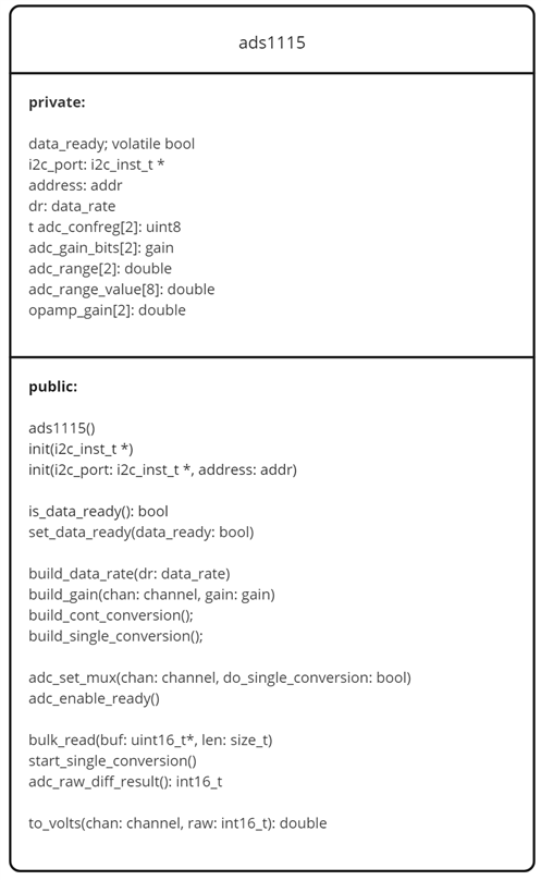
ads1115 class
I've designed it as an OO API for the Data Acquisition Board for Pi Pico. It's able to handle one ADC, configured for differential input.
If you have one board mounted on the Pico, the class can find it by itself. If you stack multiple boards, you can create multiple objects, and pass them the address of the ADC they have to manage.
The class doesn't have a sample data buffer. I rely on the firmware to provide a buffer that it can use to collect a set of samples.
constructor
The constructor initialises data members and state. It doesn't do any other functionality. That's common for embedded classes. In embedded, objects (and other data) get instantiated staticly, to prevent using the heap. In that case, you don't have easy control when they are created. Definitely before you have the chance to initiate the i2c peripherals.
ads1115::ads1115() : data_ready(false), i2c_port(nullptr), address(addr::A_LAST), dr(data_rate::DR_860) {}
The keen eye will spot that the data members are strongly typed. Read the "constants" subsection below for the explanation.
init
This is where the object learns what ADC IC it has to control.
There are two flavours. One that looks for an installed ADC IC and then initialises itself to talk to that one. If more than one daq board is mounted, the one with the lowest address is found. A second one initialises itself for a given IC address. Use that one if you have more than one daq board mounted. In that case, you'd create an object per board. Each object will know how to address the right ADC.
// configure for first found IC
bool ads1115::init(i2c_inst_t *i2c_port) {
    bool found = false;
    uint8_t u;
    uint8_t buf[3] = {(uint8_t)reg::REG_CONFIG};
    // is the ADC chip installed?
    for (u = (uint8_t)addr::A_0; u < (uint8_t)addr::A_LAST; u++) { // test both board I2C addresses
        i2c_write_blocking(i2c_port, u, buf, 1, false);
        if (i2c_read_blocking(i2c_port, u, buf, 2, false) != PICO_ERROR_GENERIC) {
            found = ads1115::init(i2c_port, (addr)u); // chip found!
            break;
        }
    }
    return found;
}

// configure for IC with provided address
bool ads1115::init(i2c_inst_t *i2c_port, addr address) {
    this->i2c_port = i2c_port;
    this->address = address;
    return true;
}
prepare
These functions gather all info needed to configure the ADC, before actually starting the sample. They are the counterparts of Shabaz' build_***() functions. They prepare the register configuration values before they are actually written to the ADC.
// these build_xxx functions set up the local config register variables,
// for later programming into the ADC.

void ads1115::build_data_rate(data_rate dr) {
    this->dr = dr;
    adc_confreg[1] &= ~0xE0; // clear the DR bits
    adc_confreg[1] |= ((uint8_t)dr << 5); // set the DR bits
}

void ads1115::build_gain(channel chan, gain gain) {
    adc_range[(uint8_t)chan] = adc_range_value[(uint8_t)gain];
    adc_gain_bits[(uint8_t)chan] = gain;
    adc_confreg[0] &= ~0x0E; // clear the PGA bits
    adc_confreg[0] |= ((uint8_t)gain << 1); // set the PGA bits
}

void ads1115::build_cont_conversion() {
    adc_confreg[1] &= ~0x01; // clear the single-shot mode bit
}

void ads1115::build_single_conversion() {
    adc_confreg[1] |= 0x01; // set the single-shot mode bit
}
These members only change the object state. There's no communication with the ADC at all.
action, sample
These members talk to the IC. Registers are set, multiplexer configured, Ready pin behaviour set up, samples taken.
// selects either the first or second channel on the ADC board
// this ends up programming the entire config register
// if do_single_conversion is 1 then a single conversion will be immediately started.
void ads1115::adc_set_mux(channel chan, bool do_single_conversion) {
uint8_t mux;
uint8_t buf[3];
switch(chan) {
case channel::CH_AIN1:
mux = (uint8_t)diff::DIFF_0_1;
break;
case channel::CH_AIN2:
mux = (uint8_t)diff::DIFF_2_3;
break;
}
adc_confreg[0] &= ~0x70; // clear the MUX bits
adc_confreg[0] |= (mux << 4); // set the MUX bits
buf[0] = (uint8_t)reg::REG_CONFIG;
buf[1] = adc_confreg[0];
buf[2] = adc_confreg[1];
if (do_single_conversion) {
buf[1] |= 0x01; // set MODE bit to single-shot mode
buf[1] |= 0x80; // set START bit to start conversion
}
i2c_write_blocking(i2c_port, (uint8_t)address, buf, 3, false);
}
void ads1115::adc_enable_ready() {
uint8_t buf[3];
buf[0] = (uint8_t)reg::REG_LO_THRESH;
buf[1] = 0x00;
buf[2] = 0x00; //Lo_thresh MS bit must be 0
i2c_write_blocking(i2c_port, (uint8_t)address, buf, 3, false);
buf[0] = (uint8_t)reg::REG_HI_THRESH;
buf[1] = 0x80;
buf[2] = 0x00; //Hi_thresh MS bit must be 1
i2c_write_blocking(i2c_port, (uint8_t)address, buf, 3, false);
}
void ads1115::bulk_read(uint16_t* buf, size_t len) {
uint8_t* begin = (uint8_t*)buf;
uint8_t* end = ((uint8_t*)buf) + len;
uint8_t reg = (uint8_t)reg::REG_CONVERSION;
i2c_write_blocking(i2c_port, (uint8_t)address, ®, 1, false);
set_data_ready(false);
while (begin < end) {
while(!is_data_ready()) {/* wait */ }
set_data_ready(false);
i2c_read_blocking(i2c_port, (uint8_t)address, begin, 2, false);
begin += 2;
}
}
void ads1115::start_single_conversion() {
uint8_t buf[3];
build_single_conversion();
buf[0] = (uint8_t)reg::REG_CONFIG;
buf[1] = adc_confreg[0];
buf[2] = adc_confreg[1];
i2c_write_blocking(i2c_port, (uint8_t)address, buf, 3, false);
}
// read the conversion register
uint16_t ads1115::adc_raw_diff_result() {
uint16_t buf;
uint8_t* buf8_ptr = (uint8_t*)&buf;
*buf8_ptr = (uint8_t)reg::REG_CONVERSION;
i2c_write_blocking(i2c_port, (*this)(address), buf8_ptr, 1, false);
i2c_read_blocking(i2c_port, (*this)(address), buf8_ptr, 2, false);
return(buf);
}
Although the i2c traffic delivers the bytes in a sample word in the wrong order for the RP2040 endian, the bytes of a sample aren't swapped in the class. It's a design choice, to spend as little time as possible in the sample blocks. Discuss if you 'd do that differently.
conversion ready
These function add support for the sample timing. Optional when running in single mode. In bulk mode, something has to tell our object that the next sample is ready. You can either use an interrupt from the ADC RDY pin (I use that in my example) or a timer interrupt, to inform the class that the next sample is ready to be read from the conversion register.
    inline bool is_data_ready() {return data_ready;}
    inline void set_data_ready(bool data_ready) {this->data_ready = data_ready;}
convert
This member knows how to translate a raw sample into a voltage. It expects that the sampled word has its bytes swapped.
    // convert the raw value to volts present at the ADC input
    // adjust for opamp gain
    inline double to_volts(channel chan, uint16_t raw) {
        return (double)(((int16_t)raw) * (adc_range[(uint8_t)chan] / 32768.0)) / opamp_gain[(uint8_t)chan];
    }
A theme in the design is that the samples aren't converted to signed raw values or floating point voltages. Unless needed. Most of the statistics can run on the raw 2-complement results. When needed, the STL can be used to transform these values into a different representation. In my example code, I show this. I transform the buffer of 2-compliment uint words to floating point voltages before printing them.
constants
class ads1115 {
public:
    enum class addr : uint8_t {
        A_0  = 0x48,
        A_1,
        A_2,
        A_3,
        A_LAST
    };

    enum class data_rate : uint8_t {
        DR_8 = 0,
        DR_16,
        DR_32,
        DR_64,
        DR_128,
        DR_250,
        DR_475,
        DR_860
    };

    enum class gain : uint8_t {
        GAIN_6_144 = 0,
        GAIN_4_096,
        GAIN_2_048,
        GAIN_1_024,
        GAIN_0_512,
        GAIN_0_256
    };

    enum class channel : uint8_t {
        CH_AIN1 = 0,
        CH_AIN2
    };

private:
    enum class reg : uint8_t {
        REG_CONVERSION = 0x00,
        REG_CONFIG,
        REG_LO_THRESH,
        REG_HI_THRESH
    };

    enum class diff: uint8_t {
        DIFF_0_1 = 0x00,
        DIFF_2_3 = 0x03
    };
I used C++ enumeration classes. That gives me strongly typed constants. A programmer can only assign a known set of values to an ADC address, register address, speed, .... That removes the need to validate the values a user passes to the class members.
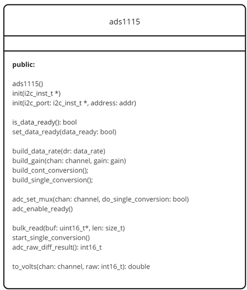
Only constants that should be available to the developer are public: address, gain, data rate, channel.
Example:
ads.build_data_rate(ads1115::data_rate::DR_860);The member function is typed, and that type only defines valid options. The code protects itself.
enum class data_rate : uint8_t { DR_8 = 0, DR_16, DR_32, DR_64, DR_128, DR_250, DR_475, DR_860 };Developers can force-override this, but then it is a wanted jailbreak. It's fair that jailbreakers should do their own error handling.
other C++ constructs: STL to process samples
I use STL Iterators, Lambda functions and Callables to work with the raw data buffer. Each of these exercises have their separate blog post. When you use these in your own code, you 'll notice that they add virtually no overhead. STL is specialised in resolving the abstractions as much as possible at compile time. In my code below, the price is equal to using C style for loops
    // buffer bytes will now get swapped,
    // and that's needed for the next actions
    // use stl iterator and lambda function
    std::for_each(std::begin(buf), std::end(buf), [](uint16_t& u){ u = u >> 8 | u << 8; }); // swap bytes

    // statistics. Prereq: bytes are already swapped

    // average
    uint16_t average = std::accumulate(std::begin(buf), std::end(buf), 0.0) / std::size(buf);
    printf("AVG = %.7f V\n", ads.to_volts(ads1115::channel::CH_AIN1, average));
    // min and max
    auto minmax = std::minmax_element(std::begin(buf), std::end(buf));
    printf("MIN = %.7f V\n", ads.to_volts(ads1115::channel::CH_AIN1, *minmax.first));
    printf("MAX = %.7f V\n", ads.to_volts(ads1115::channel::CH_AIN1, *minmax.second));

    // convert every value to voltage
    double volts[SAMPLES];
    std::transform(std::begin(buf), std::end(buf), std::begin(volts),
               [](uint16_t u){ return ads.to_volts(ads1115::channel::CH_AIN1, u); });

    // print voltage
    std::for_each(std::begin(volts), std::end(volts), [](double& d) {
        printf("SMP = %.7f V\n", d);
    });
This code works with or without the ads1115 class. It deals with the raw buffer of samples. The only time it uses the object is to call it's voltage conversion functionality.
See:
- Average bulk samples from Data Acquisition Board for Pi Pico with C++ STL
- Converting bulk samples from Data Acquisition Board for Pi Pico with C++ STL
- Min and Max bulk samples from Data Acquisition Board for Pi Pico with C++ STL
The Code
You'll find a link to the Github repository at the end of this post. The repo is a clone of Shabaz' code for the daq. I created a new branch for the OO version. That repo has a CMake file and can be built in the same way as the Pico examples from the Pico C/C++ SDK.
class header
#ifndef _ADS1115_H_
#define _ADS1115_H_

#include "hardware/gpio.h"
#include "hardware/i2c.h"

class ads1115 {
public:
    enum class addr : uint8_t {
        A_0  = 0x48,
        A_1,
        A_2,
        A_3,
        A_LAST
    };

    enum class data_rate : uint8_t {
        DR_8 = 0,
        DR_16,
        DR_32,
        DR_64,
        DR_128,
        DR_250,
        DR_475,
        DR_860
    };

    enum class gain : uint8_t {
        GAIN_6_144 = 0,
        GAIN_4_096,
        GAIN_2_048,
        GAIN_1_024,
        GAIN_0_512,
        GAIN_0_256
    };

    enum class channel : uint8_t {
        CH_AIN1 = 0,
        CH_AIN2
    };

private:
    enum class reg : uint8_t {
        REG_CONVERSION = 0x00,
        REG_CONFIG,
        REG_LO_THRESH,
        REG_HI_THRESH
    };

    enum class diff: uint8_t {
        DIFF_0_1 = 0x00,
        DIFF_2_3 = 0x03
    };

    volatile bool data_ready;
    i2c_inst_t *i2c_port;
    addr address;
    data_rate dr;
    uint8_t adc_confreg[2] = {0, 0};
    gain adc_gain_bits[2] = {gain::GAIN_2_048, gain::GAIN_2_048};
    double adc_range[2] = {2.048, 2.048};
    double adc_range_value[8] = {6.144, 4.096, 2.048, 1.024, 0.512, 0.256};
    double opamp_gain[2] = {0.38298, 0.38298};

public:
    ads1115() : data_ready(false), i2c_port(nullptr), address(addr::A_LAST), dr(data_rate::DR_860) {}

    bool init(i2c_inst_t *i2c_port); // configure for first found IC
    bool init(i2c_inst_t *i2c_port, addr address); // configure for IC with provided address

    inline bool is_data_ready() {return data_ready;}
    inline void set_data_ready(bool data_ready) {this->data_ready = data_ready;}

    void build_data_rate(data_rate dr);
    void build_gain(channel chan, gain gain);
    void build_cont_conversion();
    void build_single_conversion();

    void adc_set_mux(channel chan, bool do_single_conversion);
    void adc_enable_ready();

    void bulk_read(uint16_t* buf, size_t len);

    void start_single_conversion();
    uint16_t adc_raw_diff_result();

    // convert the raw value to volts present at the ADC input
    // adjust for opamp gain
    inline double to_volts(channel chan, uint16_t raw) {
        return (double)(((int16_t)raw) * (adc_range[(uint8_t)chan] / 32768.0)) / opamp_gain[(uint8_t)chan];
    }
};

#endif // _ADS1115_H_
class implementation
#include "ads1115.h"
// configure for first found IC
bool ads1115::init(i2c_inst_t *i2c_port) {
bool found = false;
uint8_t u;
uint8_t buf[3] = {(uint8_t)reg::REG_CONFIG};
// is the ADC chip installed?
for (u = (uint8_t)addr::A_0; u < (uint8_t)addr::A_LAST; u++) { // test both board I2C addresses
i2c_write_blocking(i2c_port, u, buf, 1, false);
if (i2c_read_blocking(i2c_port, u, buf, 2, false) != PICO_ERROR_GENERIC) {
found = ads1115::init(i2c_port, (addr)u); // chip found!
break;
}
}
return found;
}
// configure for IC with provided address
bool ads1115::init(i2c_inst_t *i2c_port, addr address) {
this->i2c_port = i2c_port;
this->address = address;
return true;
}
// these build_xxx functions set up the local config register variables,
// for later programming into the ADC.
void ads1115::build_data_rate(data_rate dr) {
this->dr = dr;
adc_confreg[1] &= ~0xE0; // clear the DR bits
adc_confreg[1] |= ((uint8_t)dr << 5); // set the DR bits
}
void ads1115::build_gain(channel chan, gain gain) {
adc_range[(uint8_t)chan] = adc_range_value[(uint8_t)gain];
adc_gain_bits[(uint8_t)chan] = gain;
adc_confreg[0] &= ~0x0E; // clear the PGA bits
adc_confreg[0] |= ((uint8_t)gain << 1); // set the PGA bits
}
void ads1115::build_cont_conversion() {
adc_confreg[1] &= ~0x01; // clear the single-shot mode bit
}
void ads1115::build_single_conversion() {
adc_confreg[1] |= 0x01; // set the single-shot mode bit
}
// selects either the first or second channel on the ADC board
// this ends up programming the entire config register
// if do_single_conversion is 1 then a single conversion will be immediately started.
void ads1115::adc_set_mux(channel chan, bool do_single_conversion) {
uint8_t mux;
uint8_t buf[3];
switch(chan) {
case channel::CH_AIN1:
mux = (uint8_t)diff::DIFF_0_1;
break;
case channel::CH_AIN2:
mux = (uint8_t)diff::DIFF_2_3;
break;
}
adc_confreg[0] &= ~0x70; // clear the MUX bits
adc_confreg[0] |= (mux << 4); // set the MUX bits
buf[0] = (uint8_t)reg::REG_CONFIG;
buf[1] = adc_confreg[0];
buf[2] = adc_confreg[1];
if (do_single_conversion) {
buf[1] |= 0x01; // set MODE bit to single-shot mode
buf[1] |= 0x80; // set START bit to start conversion
}
i2c_write_blocking(i2c_port, (uint8_t)address, buf, 3, false);
}
void ads1115::adc_enable_ready() {
uint8_t buf[3];
buf[0] = (uint8_t)reg::REG_LO_THRESH;
buf[1] = 0x00;
buf[2] = 0x00; //Lo_thresh MS bit must be 0
i2c_write_blocking(i2c_port, (uint8_t)address, buf, 3, false);
buf[0] = (uint8_t)reg::REG_HI_THRESH;
buf[1] = 0x80;
buf[2] = 0x00; //Hi_thresh MS bit must be 1
i2c_write_blocking(i2c_port, (uint8_t)address, buf, 3, false);
}
void ads1115::bulk_read(uint16_t* buf, size_t len) {
uint8_t* begin = (uint8_t*)buf;
uint8_t* end = ((uint8_t*)buf) + len;
uint8_t reg = (uint8_t)reg::REG_CONVERSION;
i2c_write_blocking(i2c_port, (uint8_t)address, ®, 1, false);
set_data_ready(false);
while (begin < end) {
while(!is_data_ready()) {/* wait */ }
set_data_ready(false);
i2c_read_blocking(i2c_port, (uint8_t)address, begin, 2, false);
begin += 2;
}
}
void ads1115::start_single_conversion() {
uint8_t buf[3];
build_single_conversion();
buf[0] = (uint8_t)reg::REG_CONFIG;
buf[1] = adc_confreg[0];
buf[2] = adc_confreg[1];
i2c_write_blocking(i2c_port, (uint8_t)address, buf, 3, false);
}
// read the conversion register
uint16_t ads1115::adc_raw_diff_result() {
uint16_t buf;
uint8_t* buf8_ptr = (uint8_t*)&buf;
*buf8_ptr = (uint8_t)reg::REG_CONVERSION;
i2c_write_blocking(i2c_port, (*this)(address), buf8_ptr, 1, false);
i2c_read_blocking(i2c_port, (*this)(address), buf8_ptr, 2, false);
return(buf);
}
example
/************************************************************************
 * adc_board_test
 * main.cpp
 * rev 1.0 - shabaz - oct 2023
 * convert to bulk mode and cpp jc 20231218
 ************************************************************************/

// ************* header files ******************

#include <stdio.h>
#include <string.h>
#include "hardware/gpio.h"
#include "pico/stdlib.h"
#include "pico/stdio.h"
#include "hardware/i2c.h"
#include "hardware/irq.h"

#include "ads1115.h"

#include <iterator>
#include <numeric>

// I2C
// set this value to 0 or 1 depending on 0-ohm resistor positions on ADC board.
// set the value to 0 if the resistors are at the I2C0 labeled position,
// set the value to 1 if the resistors are at the unlabeled position (which will be I2C1)
// if the user did not set a selection, select I2C1 (shabaz solder instructions default)
#ifndef I2C_PORT_SELECTED
#define I2C_PORT_SELECTED 1
#endif // I2C_PORT_SELECTED

// these pins are supported by the ADC board:
#define I2C_SDA0_PIN 4
#define I2C_SCL0_PIN 5
#define I2C_SDA1_PIN 6
#define I2C_SCL1_PIN 7

#define ADC_RDY 13

// sample batch size in bulk mode
#define SAMPLES 860

// ************ global variables ****************

i2c_inst_t *i2c_port;
ads1115 ads = ads1115();

// ********** functions *************************

void rdy_callback(uint gpio, uint32_t events) {
    ads.set_data_ready(true);
}

// board initialisation
void board_init() {
    // I2C init
    if (I2C_PORT_SELECTED == 0) {
        i2c_port = &i2c0_inst;
    } else {
        i2c_port = &i2c1_inst;
    }
    i2c_init(i2c_port, 1000*1000);// 1 MHz I2C clock

    if (I2C_PORT_SELECTED == 0) {
        gpio_set_function(I2C_SDA0_PIN, GPIO_FUNC_I2C);
        gpio_set_function(I2C_SCL0_PIN, GPIO_FUNC_I2C);
        gpio_pull_up(I2C_SDA0_PIN); // weak pull-ups but enable them anyway
        gpio_pull_up(I2C_SCL0_PIN);
    } else {
        gpio_set_function(I2C_SDA1_PIN, GPIO_FUNC_I2C);
        gpio_set_function(I2C_SCL1_PIN, GPIO_FUNC_I2C);
        gpio_pull_up(I2C_SDA1_PIN); // weak pull-ups but enable them anyway
        gpio_pull_up(I2C_SCL1_PIN);
    }

    // trigger and listener for ADC RDY pin
    gpio_init(ADC_RDY);
    gpio_pull_up(ADC_RDY);
    gpio_set_dir(ADC_RDY, false);
    gpio_set_irq_enabled_with_callback(ADC_RDY, GPIO_IRQ_EDGE_RISE, true, &rdy_callback);

}

// ************ main function *******************
int main(void) {
    uint16_t buf[SAMPLES];

    stdio_init_all();
    board_init();

    // check what ADC boards are installed, and initialize them
    ads.init(i2c_port);
    sleep_ms(5 * 1000);

    ads.build_data_rate(ads1115::data_rate::DR_860);
    ads.build_gain(ads1115::channel::CH_AIN1, ads1115::gain::GAIN_2_048); // +- 2.048V


    ads.build_cont_conversion();
    ads.adc_set_mux(ads1115::channel::CH_AIN1, false);

    ads.adc_enable_ready();
    ads.set_data_ready(false);
    ads.bulk_read(buf, sizeof buf);

    // buffer bytes will now get swapped,
    // and that's needed for the next actions
    // use stl iterator and lambda function
    std::for_each(std::begin(buf), std::end(buf), [](uint16_t& u){ u = u >> 8 | u << 8; }); // swap bytes

    // statistics. Prereq: bytes are already swapped

    // average
    uint16_t average = std::accumulate(std::begin(buf), std::end(buf), 0.0) / std::size(buf);
    printf("AVG = %.7f V\n", ads.to_volts(ads1115::channel::CH_AIN1, average));
    // min and max
    auto minmax = std::minmax_element(std::begin(buf), std::end(buf));
    printf("MIN = %.7f V\n", ads.to_volts(ads1115::channel::CH_AIN1, *minmax.first));
    printf("MAX = %.7f V\n", ads.to_volts(ads1115::channel::CH_AIN1, *minmax.second));

    // convert every value to voltage
    double volts[SAMPLES];
    std::transform(std::begin(buf), std::end(buf), std::begin(volts),
               [](uint16_t u){ return ads.to_volts(ads1115::channel::CH_AIN1, u); });

    // print voltage
    std::for_each(std::begin(volts), std::end(volts), [](double& d) {
        printf("SMP = %.7f V\n", d);
    });

    while (true) {
    }
}
Enjoy!
Source: https://github.com/jancumps/adc_board_test/tree/object-oriented
Firmware (.uf2): adc_board_test.zip

