


Previous entries in this blog series:
- Pi Alarm System - Part 1: Project and components description
- Pi Alarm System - Part 2: Wireless sensors
I've finally been able to spend some time on the Pi Alarm project this weekend, so here's a progress update!
For the Pi Alarm System, I'm using various Raspberry Pi accessories/extension boards, such as: PiFace Digital, Adafruit LCD and Keypad kit, Pi Rack, etc ...
In this post, I'll be describing how I connected different parts and got them up and running.
Pi NoIR
For the installation and use of the camera, I will refer to my Pi NoIR RoadTest: http://www.element14.com/community/roadTestReviews/1638
The camera will be used in the same way as for the Santa Catcher. You can find more information here: Raspberry Pi Santa Catcher with Pi NoIR and PiFace CAD
Adafruit RGB LCD and Keypad Kit
Assembly
The LCD and Keypad come in the form of a kit.
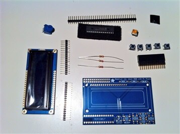
I got my soldering iron hot and started soldering. Fifteen minutes later the kit was assembled and ready to use.
<html><head><title>Jive SBS</title></head>
<body><font face="arial,helvetica,sans-serif">
<b>Error</b><br><font size="-1">
An general error occurred while processing your request.
</font></font></body></html>
I2C Support
The LCD and Keypad kit uses I2C for communication with the pi.
There are some configuration changes required for this to function, luckily there is a nice tutorial on Adafruit: Configuring I2C | Adafruit's Raspberry Pi Lesson 4. GPIO Setup | Adafruit Learning System
After setting up I2C on the pi, I connected the LCD and keypad, and powered the pi. I verified the LCD and keypad were detected properly:
pi@raspberrypi ~ $ sudo i2cdetect -y 1

     0  1  2  3  4  5  6  7  8  9  a  b  c  d  e  f
00:          -- -- -- -- -- -- -- -- -- -- -- -- --
10: -- -- -- -- -- -- -- -- -- -- -- -- -- -- -- --
20: 20 -- -- -- -- -- -- -- -- -- -- -- -- -- -- --
30: -- -- -- -- -- -- -- -- -- -- -- -- -- -- -- --
40: -- -- -- -- -- -- -- -- -- -- -- -- -- -- -- --
50: -- -- -- -- -- -- -- -- -- -- -- -- -- -- -- --
60: -- -- -- -- -- -- -- -- -- -- -- -- -- -- -- --
70: -- -- -- -- -- -- -- --
The LCD and keypad were detected and with address 0x20. Time for some testing.
Testing
There is a tutorial on how to use the LCD and keypad and sample code on the Adafruti website: http://learn.adafruit.com/adafruit-16x2-character-lcd-plus-keypad-for-raspberry-pi/usage
I downloaded and executed the example code:
pi@raspberrypi ~ $ git clone https://github.com/adafruit/Adafruit-Raspberry-Pi-Python-Code.git
Cloning into 'Adafruit-Raspberry-Pi-Python-Code'...
remote: Reusing existing pack: 461, done.
remote: Total 461 (delta 0), reused 0 (delta 0)
Receiving objects: 100% (461/461), 155.96 KiB, done.
Resolving deltas: 100% (196/196), done.
pi@raspberrypi ~ $ cd Adafruit-Raspberry-Pi-Python-Code
pi@raspberrypi ~/Adafruit-Raspberry-Pi-Python-Code $ cd Adafruit_CharLCDPlate
pi@raspberrypi ~/Adafruit-Raspberry-Pi-Python-Code/Adafruit_CharLCDPlate $ sudo python Adafruit_CharLCDPlate.py
This cycled through some different background colors and detected button presses.
The output of the script looked like this:
Cycle thru backlight colors
Red
Yellow
Green
Teal
Blue
Violet
Off
On
Try buttons on plate
Select
Left
Up
Down
Right
And the result as follows:
Programming the menus
I programmed a simple menu structure to enable/disable the alarm system. This can later be extended to use some kind of pin code for verification before allowing any changes.
The menu is programmed in Python and behaves as follows:
- At startup a message is displayed for 5 seconds. The LCD is then cleared and turned off, waiting for user input.
- When the SELECT button is pressed, the menu is displayed
- Using the UP and DOWN buttons, a menu entry can be selected
- Pressing SELECT again confirms the selection and enables/disables the alarm system
- When no button is pressed for 5 seconds, the LCD is cleared and turned off, waiting for new user input
A video demonstrating the menus:
PiFace Digital
Unlike the Adafruit LCD and Keypad kit, the PiFace Digital comes pre-assembled and ready to use.
<html><head><title>Jive SBS</title></head>
<body><font face="arial,helvetica,sans-serif">
<b>Error</b><br><font size="-1">
An general error occurred while processing your request.
</font></font></body></html>
Installation
There is a step-by-step guide on how to install the necessary python modules and on how to enable SPI on the pi, available on the PiFace website: http://www.piface.org.uk/guides/Install_PiFace_Software/
I followed the instructions and could then start using the PiFace Digital.
Testing
A first test I executed, was to connect some LEDs to the outputs of the PiFace and see if I could properly control them.
The goal is to light up a green LED when the alarm system is disabled, a red one when enabled.
Ultimately, the LEDs should light up as a result of the actions on the LCD and keypad.
There are also two usable relays on the PiFace Digital.
Even though the relays are rated for 250V-10A, the PiFace documentation states they can only be used for 20V-5A max.
This is still enough to connect a rotating beacon light and a high power siren, both running on 12V.
Pi Rack
To be able to connect more than one board at the time to the Raspberry Pi, there is an accessory called the "Pi Rack".
This allows us to connect up to four extension boards on the Raspberry Pi's GPIO pins.
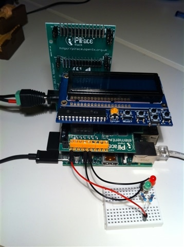
I connected both the PiFace Digital and the Adafruit LCD and Keypad to the Pi Rack on top of the Raspberry Pi.
The Adafruit LCD and Keypad worked immediatly. The PiFace Digital however, didn't.
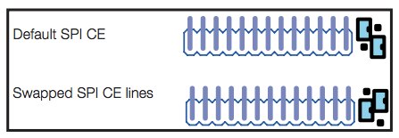
pifacedigitalio.core.NoPiFaceDigitalDetectedError: No PiFace Digital board detected (hardware_addr=0, bus=0, chip_select=0).
I had to swap the SPI jumpers for the PiFace Digital from "default" to "swapped" CE lines. I was then able to use the PiFace Digital again.
Combining LCD/Keypad with PiFace Digital
With different elements working, It was time to combine some functionality.
I've extended the code to control the Adafruit LCD and Keypad to also perform some actions on the PiFace Digital.
The PiFace Digital controls two LEDs to show the state of the alarm system, as configured using the LCD and Keypad.
The code:
Next
There is still some work to be done before the system is complete:
- Listen for the wireless sensors to know when to trigger the alarm
- Notification of the owner using an Arduino GSM Shield
- Testing, testing, testing ...
