This blog post contains at least two topics, both (hopefully) interesting. One topic concerns how to code new functionality into an exciting open source project called the Pico SCPI labTool. The end result discussed here provides four analog voltage measurement inputs! The second topic is how to add such features to other people’s projects using GitHub! Both topics will be discussed together simultaneously. This blog post is a joint effort by Jan Cumps and shabaz
Table of Contents
- Introduction
- I Just Want the Functionality
- Feature Development Methodology
- Desired Functionality
- Switching to the Development Branch
- Creating your Feature Branch
- Update the Cloud Repository with your Feature Branch
- Write the Code!
- Building the Code
- Testing the Code
- Ready for Review
- Project Owner’s Review
- Cleaning Up
- Update your Repo and Local Code
- Summary
Introduction
The Pico SCPI labTool (PST) is literally just a Pi Pico, but with some special firmware developed by Jan Cumps , that allows it to be controlled by popular software applications. The high-res analog measurements are provided courtesy of a Texas Instruments (TI) analog-to-digital converter (ADC), available at very low-cost as a ready-made module. For under $10, the end result is a system that can perform measurements and can also control things.
The diagram below shows how easy it is to set up (only the new high-res analog inputs are shown, but there are also digital inputs/outputs!):

The Pico SCPI labTool (PST) allows one to control and monitor things such as relays, temperature sensors, and voltage and current probes, in fact, a vast amount of hardware, all using a standards-based communication method that allows control using Python, LabVIEW, MATLAB and so on.
In a previous blog post, PST was briefly explored, and it was explained how one could create such a tool for themselves by building the code and uploading it to a Pi Pico. By the end of that blog post, the result was a functioning PST, and it was possible to set a pin on and off, under control from the PC, from all sorts of compatible software.
This blog post discusses how to extend the PST to add brand-new functionality. In my case, it was desired to add a 16-bit ADS1115 analog-to-digital converter (ADC).
By the end of this blog post, you should hopefully be familiar with how to add new stuff to the Pico SCPI labTool, and how to get your work into the open-source code’s repository so that others can benefit from the enhancements too.
I Just Want the Functionality
If you don't wish to create a custom feature, you don't need to read any more of this blog post; you can simply go to the Pico SCPI labTool GitHub page, and then either download a ready-made release (if the listed functionality is sufficient for you), or build from scratch by following the steps here: PST.. Have you worked with the Pico SCPI labTool?
If you plan to create custom features, then read on!
Feature Development Methodology
The methodology closely precisely follows that described here: GitHub for Beginners: Feature Development for Projects
That blog post is a reference for how things will be done in this blog post. I’ll be using CLion as the interactive development environment (IDE), but that blog post shows how to use equivalent capability with Visual Studio Code; it’s up to you which you choose!
Either way, it is highly recommended to read that blog post first so that you’re aware of the steps that will be taken in this blog post.
Desired Functionality
As mentioned, the aim was to make the Pico SCPI labTool work with a high(ish) resolution ADC so that users could (say) attach sensors and then obtain measurements from their PC, using (say) LabVIEW or Python.
The Pico SCPI labTool in fact already supports analog inputs; Jan has already developed that feature, and it allows the user to access the Pi Pico’s in-built analog inputs using the following SCPI query (where # is the desired analog channel number):
ANA:INP#:RAW?
For the new feature, it was decided to use the following syntax:
ANA:HIRES:INP#:RAW?
The idea being, that for now, my ADC feature would be described using the text HIRES, and if anyone else wishes to extend further with additional ADC types, they could simply pick a word to describe their ADC too.
Note: It will be worth consulting with people (e.g. on any of the Pico SCPI labTool threads) and particularly Jan, to brainstorm how to best describe your desired functionality in SCPI syntax.
The diagram earlier shows how the ADC board would be attached to the Pi Pico; it makes use of an I2C bus.
The ADS1115 chip supports up to four single-ended inputs, labeled A0-A3 in the diagram above, and I would expect the user to type the following to read channel the first channel (A0):
ANA:HIRES:INP0:RAW?
The returned raw value would be a number between 0 and (2^15)-1, i.e 32767. The user could then convert it to a voltage value if desired, using a simple multiplication or division. The gain of the ADS1115 chip would be also be fixed for now, to a useful range of 0 to 2.048 V. Therefore, if (say) a user wished to know what voltage was present at the A0 input, they could type (in pseudocode):
val_integer = instrument_query("ANA:HIRES:INP0:RAW?")
voltage = (float(val_integer) / 32767.0) * 2.048
print("voltage is ", voltage)
That was pretty much all the functionality that was desired for now!
Switching to the Development Branch
If you’ve followed the blog post PST.. Have you worked with the Pico SCPI labTool? then you already know how to build the code and how to transfer it to the Pi Pico and run some basic tests. Specifically, what got discussed was how to create a copy of the repository (known as a fork operation) to have your own repo stored in the GitHub cloud and then download a local copy from your repo to your PC (known as a clone operation) and then how to build the main branch code. (Note: if that doesn't make sense, please check out that blog post first, and then read GitHub for Beginners: Feature Development for Projects because those two blogs will help explain things in a bit more detail).
It is possible with GitHub to have multiple branches of code. In the case of the Pico SCPI labTool project, the author Jan has a separate development branch, which contains the new features that will eventually be merged into the main branch.
If you look closely at the bottom-right of the CLion interactive development environment (IDE), you’ll see you are on the main branch. Visual Studio Code shows it in a similar way, but on the bottom-left side; see the earlier blog post to see the detail.

If you click on that, you can select a different branch. As mentioned, we are interested in the latest development branch that Jan has created (and which is in your fork of the repo), since that is a candidate for future merging by Jan into the main branch. If you want to add a new feature, then it’s best to look for that development branch, and it will have more recent features in it that the main branch does not.
In the screenshot below, I selected the development branch called feature-set-2 and selected Checkout.
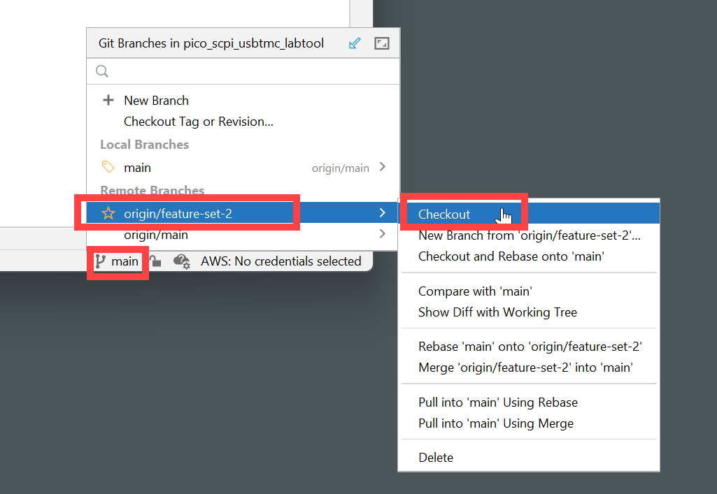
You’ll see a green success pop-up appear, and now you’ll see that the correct feature branch is selected at the bottom-right, and now if you build the code, you’ll have all the features from that branch.

Note that if you ever need to update the content from the feature branch (for instance, if Jan adds some new features) you can click on the Update arrow icon as shown in the screenshot below; it is part of the Git Toolbar in CLion.

The screenshot above shows that Jan made some changes at 14:29 and 14:28, and they will now be on your local PC.
As a sanity check, click on the hammer icon as discussed in the blog post PST.. Have you worked with the Pico SCPI labTool? and the code should successfully build. You could upload the firmware onto the Pico if you wished to try out the new features (if there are any).
Creating your Feature Branch
Now that you’ve switched to the development branch, you can create your own branch off it, known as a feature branch, specifically for developing your feature. The new branch will be just local to your PC, but eventually, you’ll publish it to the cloud. Go to Git->New Branch and give it a name, such as (in my case) shabaz-ads1115-feature. Make sure that Checkout Branch is checked, as shown in the screenshot below, and then click on Create.
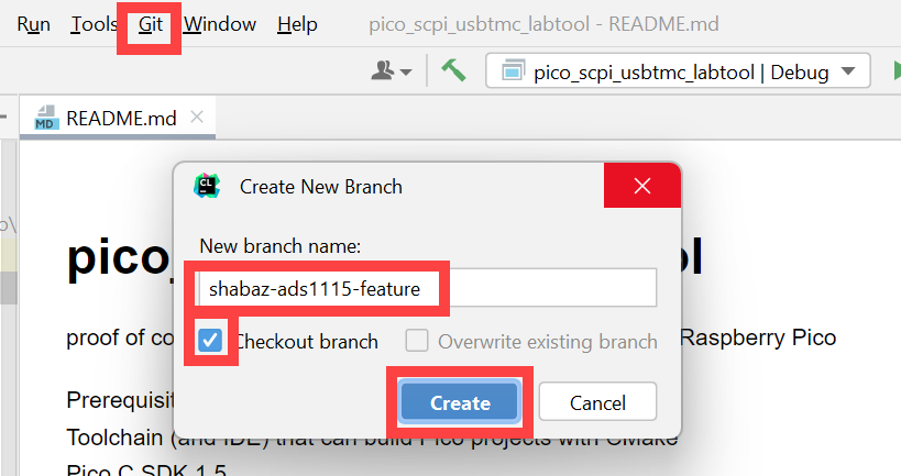
You should see a green success message appear at the bottom of the window:

As mentioned earlier, this feature branch is local to your PC currently, but it’s good to update the cloud with the same branch so that others can be aware of what you’re working on. That’s discussed next.
Update the Cloud Repository with your Feature Branch
It’s a good idea to immediately publish the information that you’ve created a local branch so that others know what you’re working on. This is easy to do with CLion. Simply click on the Push icon.
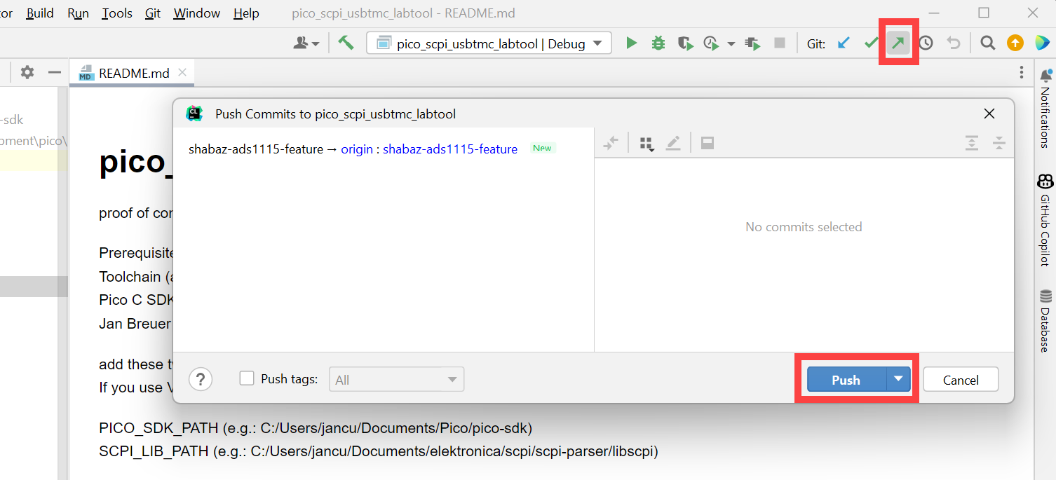
Write the Code!
Creating New Files
Generally, if you’re creating new functionality, then you’re highly likely to need new source and header files. I followed the existing pattern that Jan Cumps had used, and created a new folder called adc16, and then created the files there. To do this, right-click in the project explorer in the location where you wish the item to be created (i.e. select the source folder and then right-click on it), and then select New->Directory and then when the new directory is created, select that directory and then right-click on it and select New->C/C++ Source File or New->C/C++ Header File.
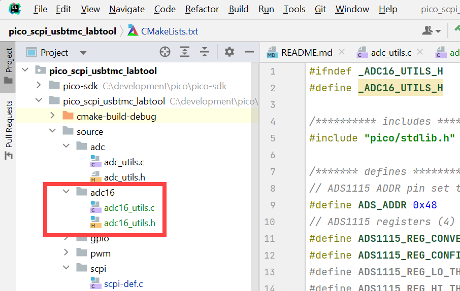
Click on Add when an Add Files to Git window appears.
After you click on Add in the pop-up window, you’ll see that the new files are displayed in green in the project explorer, rather than black. You don’t have to do it immediately (you may wish to add some code to the files first) but to make them black, right-click on the files and select Git->Add, and then once you’ve done that for both of them, then click on the Commit icon.
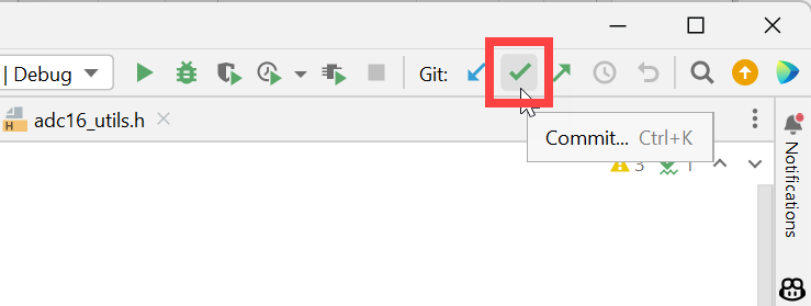
In the window that will appear, type a description (for instance your text could be Created new source and header files) and then click on the button labelled Commit. Now your local copy of the code will be appropriately labelled that the new files are part of the project, and they will turn black.
Modifying the CMakeLists.txt File
The CMakeLists.txt file will need to be modified. Here are the three most likely things that you’ll need to consider:
1. If you’re using any Pico SDK functionality that isn’t already being used by the project, then you’ll need to add to the target_link_libraries section. In my case, I needed to add hardware_i2c since that’s what my feature needs.
2. If you created a new folder and it contains a header file, then you’ll need to add it to the target_include_directories list. I added the following entry:${CMAKE_CURRENT_LIST_DIR}/source/adc16
3. If you added a new source file, then you’ll need to add an entry to the add_executable section. I added the following entry:${CMAKE_CURRENT_SOURCE_DIR}/source/adc16/adc16_utils.c
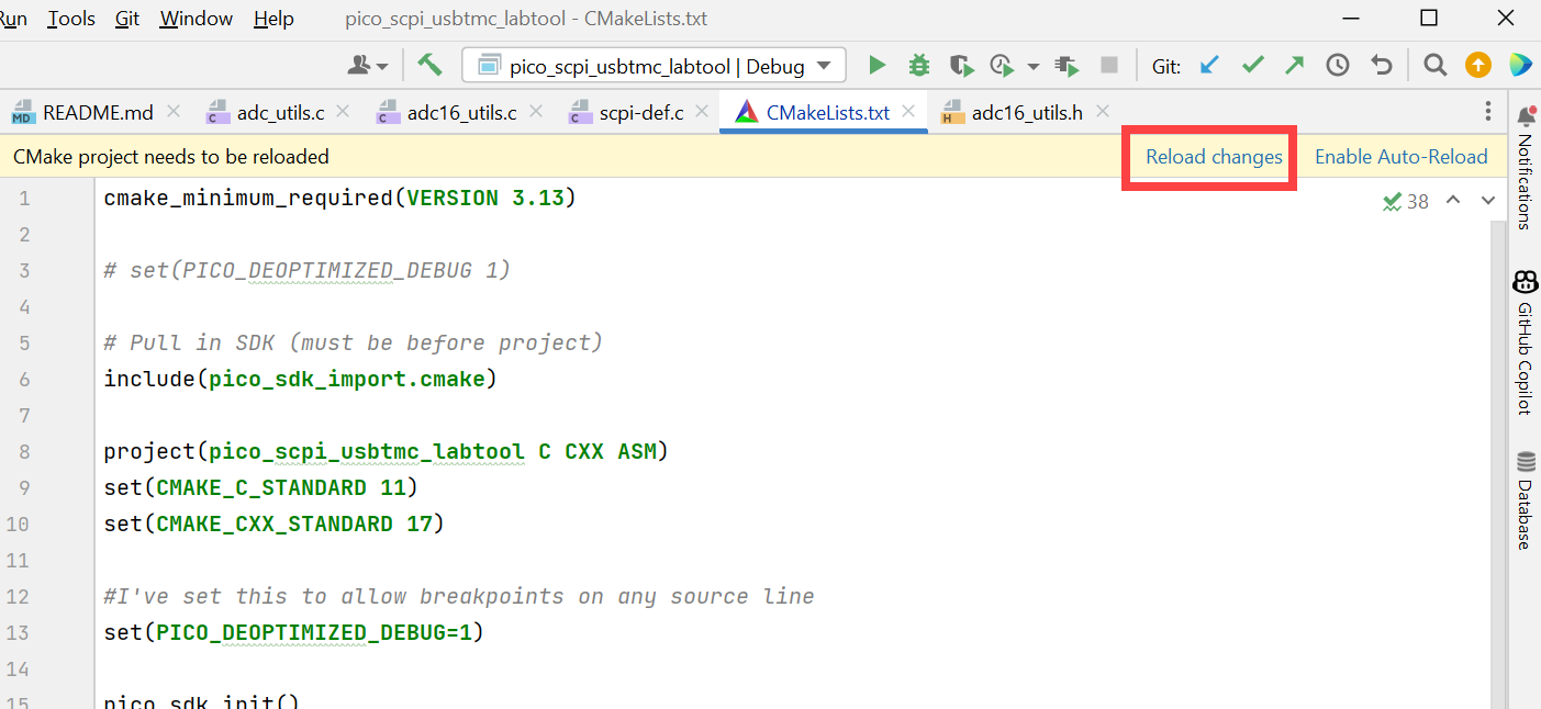
After you’ve saved the CMakeLists.txt file, click on Reload changes as shown in the screenshot below.
Incremental Development
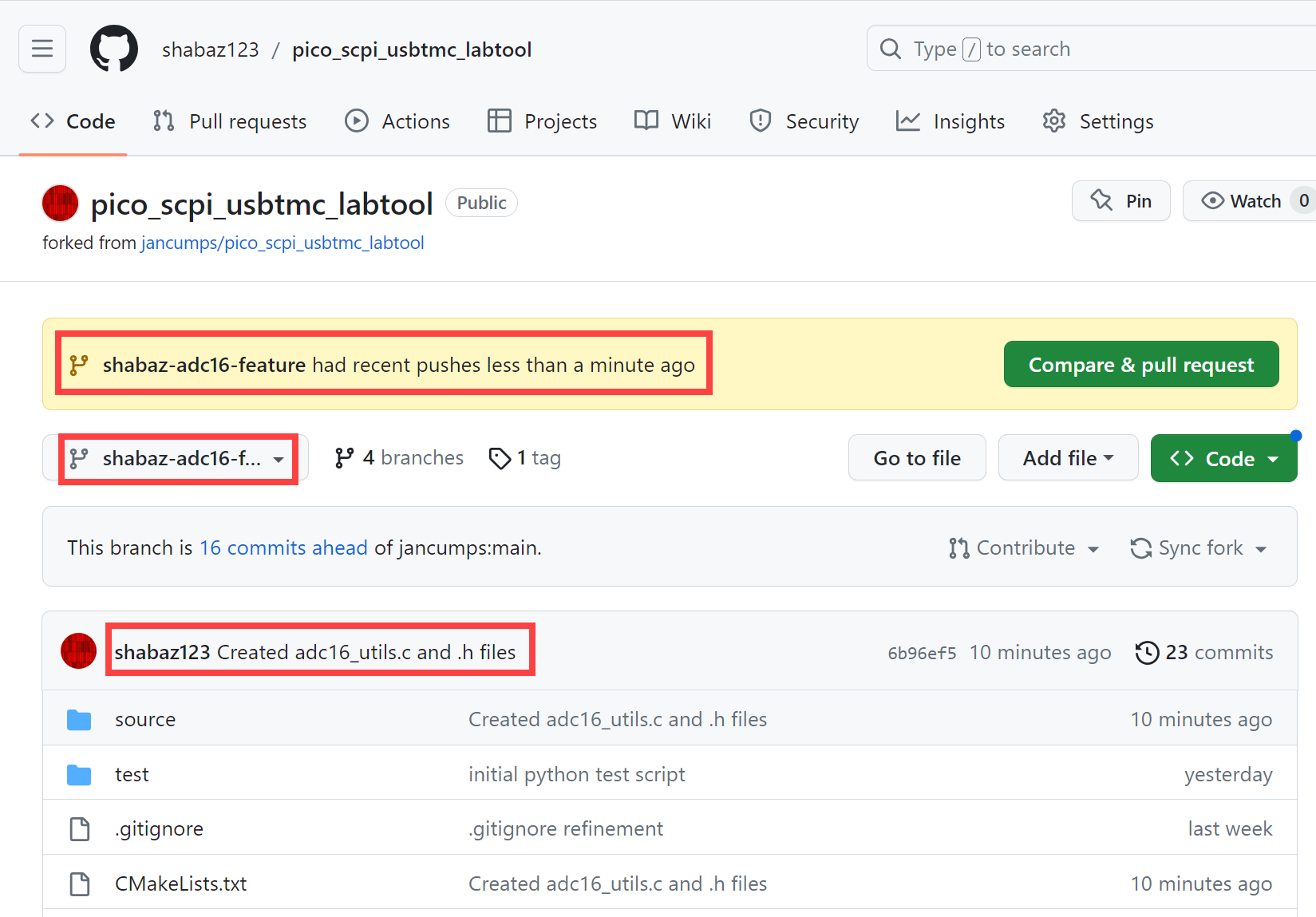
As you create and modify code, it will be good to locally make a note of your changes, by clicking on the Commit icon. A window will appear where you can type some notes. Also, you can push your local commits to the cloud so that others can look at your current in-progress work, by clicking on the Push icon. This is the view on the GitHub site when you push code to your forked repo:
Implementing the ADC Functionality
For my feature, I wished to interface with the ADS1115 chip using I2C. I created the following public functions (i.e. they were declared in the ads16_utils.h header file):
/******* functions *********/void initAdc16I2C(void); // initialize the I2C busvoid initAdc16Reg(void); // initialize the ADS1115 registersuint32_t adc16PinCount(); // return the number of pins on the ADC (4), or return 0 if no ADS1115 chip is presentuint16_t getAdc16PinAt(uint32_t index); // get the ADC value for the pin at index
In normal use I expect the first two functions to be called at initialization time, and then whenever a SCPI instruction arrives destined for the HIRES functionality, then the adc16PinCount function can be used to see if the channel is valid or not, and then the ADC measurement is obtained using the getAdc16PinAt function.
The detection of the ADS1115 chip is quite straightforward. The chip’s registers have a default value on startup. Therefore an I2C read is executed, and if the register values match what is expected, then the ADS1115 chip exists and is behaving as it should. If the chip does not respond (or responds incorrectly) then a global variable called adc16Installed is set to zero.
Regarding the measurement technique, to keep things nice and simple for the first release of this new features, it was observed from the ADS1115 PDF datasheet that the chip can optionally function in a continuous conversion mode, so the strategy was that by using that capability, no timers or interrupts would generally be needed.
Whenever the user requested a measurement via SCPI, then the latest complete conversion result would be returned. This would work fine except when the user switched from one analog channel to another; in that case, a delay of some sort would definitely be needed, to throw out any ongoing measurement, so that a fresh result from the newly chosen channel would be returned to the user. That means a maximum delay of up to twice the sampling rate (since an ongoing previous measurement cannot be aborted until it completes), plus a bit of safety margin. In other words, if a user keeps requesting the same channel repeatedly, then the measurements would be returned slightly faster than if they kept switching channels.
The code turned out to be very simple:
// get ADC result from the ADS1115
uint16_t getAdc16PinAt(uint32_t index) {
    uint16_t res;
    if (adc16Channel == index) {
        // already set to this channel
    } else {
        // switch channel, and then wait for a conversion to be done
        adc16Channel = index;
        setAdc16Mux(ADS1115_CH0 + index);
        // no need to start conversion, since we are in continuous conversion mode
        sleep_ms(80); // wait for conversion to complete. The value should be 2 * (1/SPS) + margin
    }
    res = readAdc16Meas();
    // no need to start another conversion, since we are in continuous conversion mode
    return(res);
}
A global variable called adc16Channel stores the previously requested channel. If there is no change between requested channel and that stored value, then the ADC can be immediately read using the readAdc16Meas function. On the other hand if the requested channel has changed, then the ADC needs to be instructed to switch to the new channel, and then a delay is needed before reading the measurement result from the ADC.
Connecting the ADC Functionality to the SCPI Processor
The scpi/scpi-def.c file is where the connection to the adc16_utils code needs to be made. First off, include your header file:
#include “adc16_utils.h”
Next, in the initInstrument() function, add the function calls to initialize things:
initAdc16I2C();initAdc16Reg();
Add any new desired SCPI command into the scpi_commands[] array:
{.pattern = "ANAlog:HIRES:INPut#:RAW?", .callback = SCPI_Analog16InputQ,},
Next, I created the function that would return the measurement for the channel that was requested via SCPI; it retrieves the ADC channel number from the SCPI command, and then uses that to obtain the measurement, with the getAdc16PinAt function that was described above:
static scpi_result_t SCPI_Analog16InputQ(scpi_t * context) {
    int32_t numbers[1];

    // retrieve the adc index
    SCPI_CommandNumbers(context, numbers, 1, 0);
    if (! ((numbers[0] > -1) && (numbers[0] < adc16PinCount()))) {
        SCPI_ErrorPush(context, SCPI_ERROR_INVALID_SUFFIX);
        return SCPI_RES_ERR;
    }

    SCPI_ResultUInt16(context, getAdc16PinAt(numbers[0]));
    return SCPI_RES_OK;
}
Building the Code
Now, it should be possible to build the code! Follow the earlier blog post PST.. Have you worked with the Pico SCPI labTool? which explains how to do that by clicking on the hammer icon in CLion, and then uploading the firmware file to the Pico.
Testing the Code
Check out Jan’s blog post PST.. Program the Pico SCPI labTool? to see how to work with the Pico SCPI labTool using LabView and Python. In my case, I decided to write a small bit of Python code to run some tests. The code repeatedly sent SCPI queries for random ADC channel numbers between 0 and 3.
It is worth thinking about how to make life easier when testing. For the ADC feature, it was easy to do by soldering resistors in a potential divider chain, so that each ADC channel would see a different voltage, and then coding such that the measured value should be within two percent of the expected value. As a result, I could let the program decide if it was a pass or a fail, without me needing to manually check the results.
After it ran for 1000 iterations, I felt reasonably comfortable that the code was reliable when performing valid queries. The screenshot below shows some typical output from the test program (in this case it ran for 100 iterations), with the random channel selection each time.

The best advice I have for testing, is not to ignore occasional failures! If a ‘glitch’ occurs for you then it will be guaranteed to appear for others, even if it is a one-in-a-million event. To troubleshoot any issue, keep a note (physical or mental) about any symptoms, don’t ignore things even if they seem minor! The symptoms will become important clues to help solve the problems.
Ready for Review
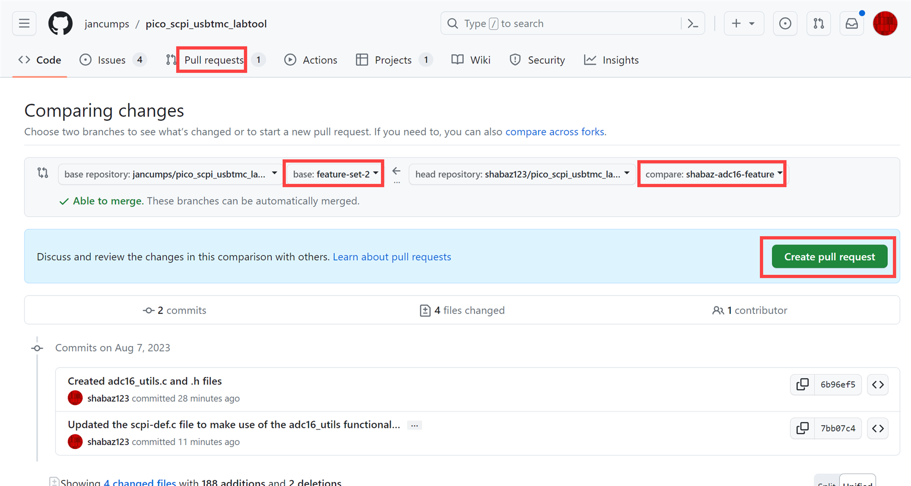
Once you’re happy with your feature code (and you’ve clicked on the Commit and the Push icons regularly, as discussed in the Incremental Development section above, and done it on completion), go to your GitHub repo, and click on the Pull Requests tab, then click on New Pull Request.

The screenshot below shows what needed to be configured. Select from the drop-down boxes the destination and source branches. The destination is the development branch, and the source is your feature branch. Then I clicked on Create pull request.
There will be a drop-down to select Create draft pull request. Write some detailed notes for Jan to understand what you’re requesting to be reviewed and merged:
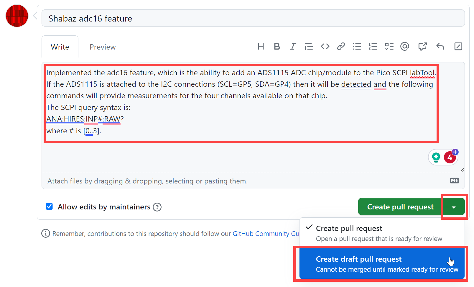
Finally, further down the page there should be a Ready for Review button. Click on that and then send the page URL to Jan.

Project Owner’s Review
At Jan’s end, all the code you’ve created or modified will be visible for review:
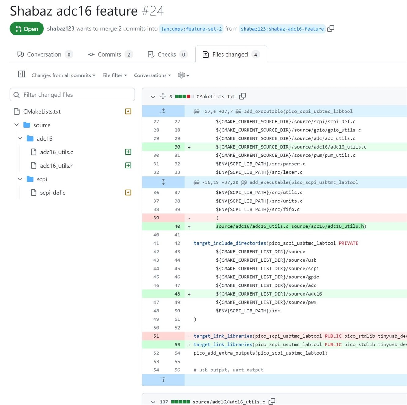
If Jan is happy with it, and if there are no conflicts then Jan will click on Merge pull request:

Cleaning Up
Once the project owner (i.e. Jan) has merged your code into the development branch, you can now delete your local feature branch and cloud feature branch. To delete it locally, click on the branch name at the lower-right in CLion, and select the branch to delete, and then click on Delete as shown in the screenshot below.
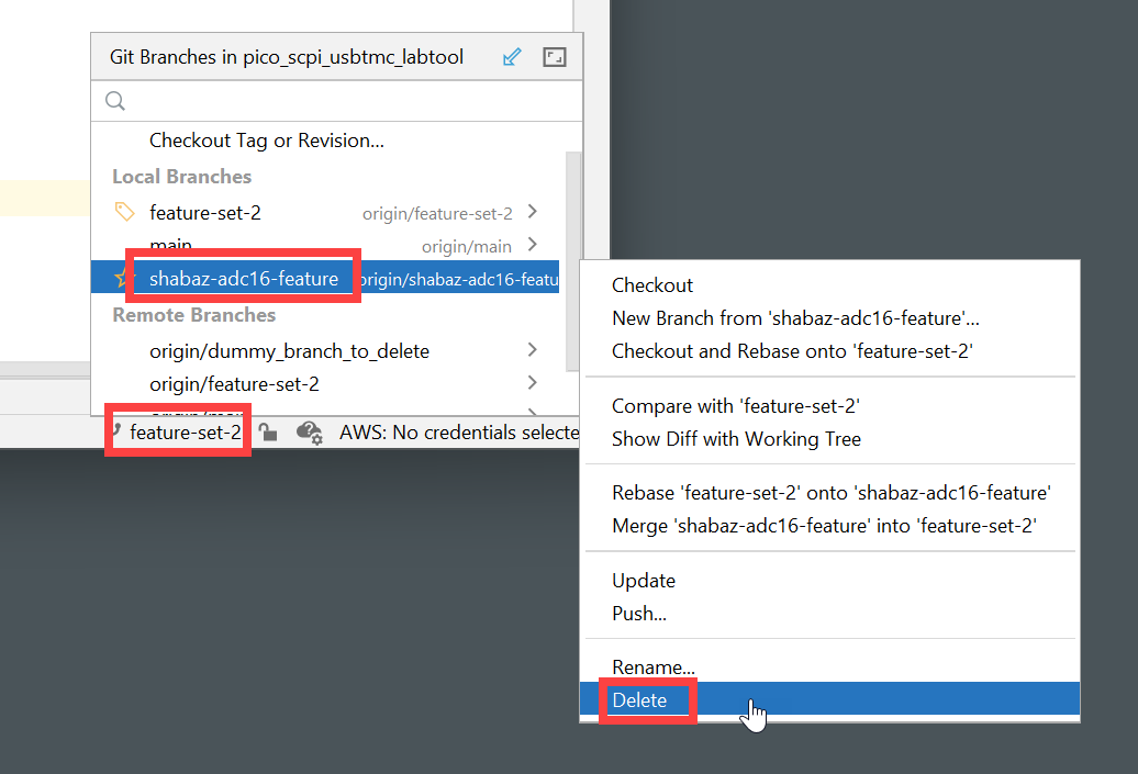
To delete the branch in the repo, go to your GitHub repo and click on branches:
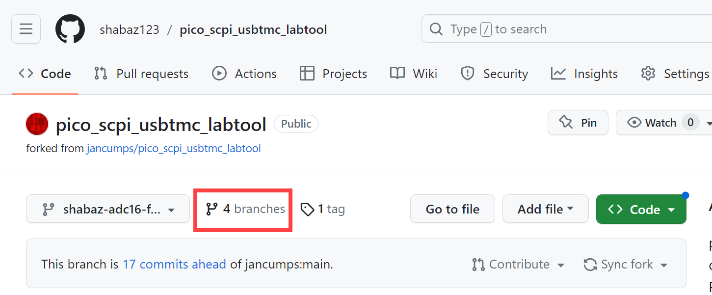
Next, click on the trashcan icon next to the feature branch:

Update your Repo and Local Code
Once the project owner (i.e. Jan) has merged your code into the development branch, you can ‘sync’ your branch in the cloud.
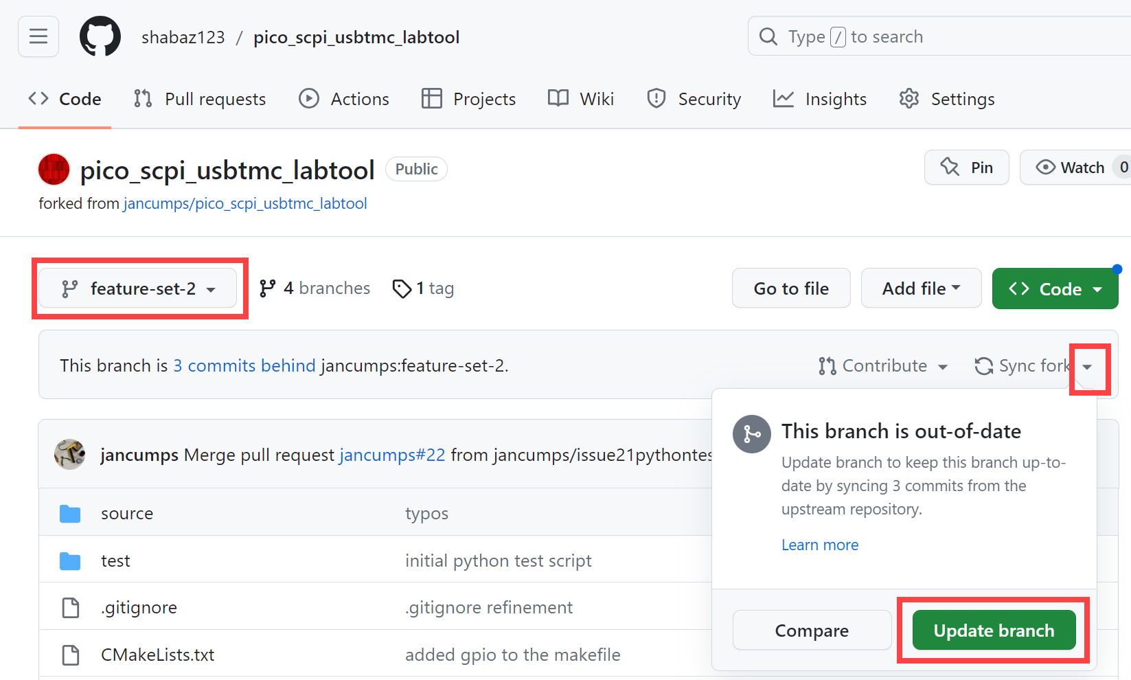
Then, switch to the development branch in CLion and click on the Update icon on the CLion Git Toolbar.
Now you can build the code and it should contain all the features in the development branch, including your own! You are now officially a contributor to another person’s open source GitHub project!
You'll get a GitHub badge the first time you do this.

Summary
A high-resolution ADC was connected to a Pi Pico, and it was possible to extend the Pico SCPI labTool to work with it! The code was then successfully merged into the official project repository, so that anyone can have access to it.
Hopefully, the steps that were detailed, along with the code changes, should provide a start if you wish to add your own functionality.
Thanks for reading.
