


Introduction
December has been a good month for USB-C Power Delivery projects and experimentation. I hope it continues into the next year.
Here are some new blog posts that were created during December! They could be of interest to anyone curious about USB-C Power Delivery (also known as USB-C PD) and what it’s all about:
USB Type-C and Power Delivery: Any Interest?
100W USB Type-C Power Delivery Source: Getting Started
Hot Air Tool Upgrade - Quick TR1300A
A Soldering Iron for Christmas
USB PD - CC decoding adventures
This quick blog post describes a simple Pi Pico based tool for getting different voltages out of mobile phone chargers.

Using this project, it can be possible to obtain 5V, 9V, 12V, 15V or 20V out of a phone charger, and this could be handy for all sorts of purposes. However, this is not a complete project; it is more for experimenting with USB-C PD. I definitely wouldn’t recommend this project to act as a standalone power supply for instance, please don’t try to misuse this project for that purpose. It’s strictly for experimentation. There’s no current-limiting, and no error-handling. Also, not all USB-C chargers will support the five voltages listed above. For instance, Anker chargers seem to omit 12V capability.
The project supports USB-PD version 2.0 capabilities. There is a more advanced capability called PPS which would allow more granular voltage setting, but that requires USB-PD 3.0 support, which this project does not have.
How is it Used?
This project is in effect a Python (actually MicroPython) library. You can load it onto the Pi Pico, and then type Python commands to choose what voltage you want. If desired, the project could be easily extended to have button inputs, since it’s just a bit of Python code that anyone learning MicroPython on the Pico will be comfortable doing.
What’s Required?
The diagram in the introduction shows the physical topology and the items required. The USB-C charger needs to support at least USB-C PD 2.0. I have tried an Anker charger and a UGREEN charger, and they both functioned with this project. Many other chargers and power supplies will function too, provided they specify that USB-C PD 2.0 or 3.0 or higher is supported.
A board is needed that contains USB-C PD ‘Sink’ capability. I used a USB-C Sink Click board, but any other board that contains the STUSB4500 chip should be fine. A Pi Pico , or any other board that supports MicroPython is needed for this project. I have only tested with Pi Pico.
A DC Electronic Load would also be handy. I have not used these particular ones, but MP710259 or TENMA 72-13210 could be possible options depending on region.
How Does it Work?
The diagram below shows the logical view. Both the charger and the USB-C Sink Click board implement USB-C PD functions, namely the Source and Sink functions respectively. They are used to negotiate the desired voltage, and the Source function provides feedback to a power supply circuit (for instance a DC-DC converter) to adjust to the configured voltage.

The STUSB4500 USB-PD Sink chip is configured via I2C using the Pi Pico.
Connections
The following connections are required between the USB Sink Click board and the Pi Pico:
| Sink Click Pin | STUSB4500 QFN Pin | Pi Pico Name | Pi Pico Pin |
| SDA | 8 | GPIO4 | 6 |
| SCL | 7 | GPIO5 | 7 |
| INT (ALERT) | 19 | GPIO15 | 20 |
| RST (RESET) | 6 | GPIO14 | 19 |
| 3V3 | 22 (VSYS) | 3V3 | 36 |
| GND | 10 | GND | 8 |
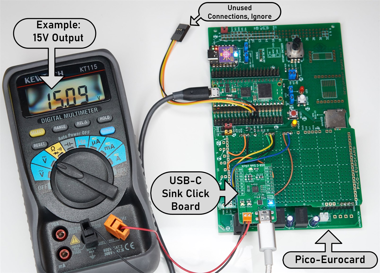
The Pico-Eurocard could be used for this project:
Installing the MicroPython Code
Follow the instructions at the raspberrypi website in order to install MicroPython onto the Pi Pico. Install the application called Thonny. Download the usbsink MicroPython code onto your PC.
Next, connect up the Pico to your PC using a USB cable, and start up Thonny. Click the red “Stop/Restart Backend” icon in the menu bar, and you should see a MicroPython command prompt appear in the lower pane. That’s the command prompt where Python commands can be typed.
In the left pane, navigate to the usbsink code, right-click on it, and select to upload it to the Pi Pico. That’s it, the code is installed : )
Using the Project
Start up Thonny if it’s not running, and make sure the command prompt is available (press the red icon mentioned earlier if the prompt is not available).
Here are some commands that can be typed at the prompt. To start, import the usbsink code, and read the contents of the device:
>>> import usbsink as pd>>> pd.read()
Now you can inspect three profiles:
>>> pd.get_voltage(1)5.0>>> pd.get_voltage(2)9.0>>> pd.get_voltage(3)5.0>>>
The first profile is always set to 5V, but the other two can be changed, for instance, to change the third profile to 15V you can type:
>>> pd.set_voltage(3,15)
To see the currently activated profile number, type the following command, and you’ll see a value returned:
>>> pd.get_pdonum()2
To set the profile to 3, type:
>>> pd.set_pdonum(3)>>> pd.softreset()
If there is a multimeter connected to the output connections on the USB Sink Click board, then you’ll see the output voltage change to 15V.
Next Steps
I have not tried all the possible commands that the STUSB4500 chip accepts. There may be errors in the code. It could be interesting to explore the commands available in the code, to see what happens. If you spot errors or make changes, please share them! I'm very new to the STUSB4500 chip, so I don't know much about it and it could be better to refer to the (unfortunately very difficult to follow) documentation and then please share your findings to help others since anyone interested in working with USB-C Power Delivery may at some point need to be able to negotiate different voltages to see what happens with any equipment under test.
Summary
This simple project can be used to experiment a bit with USB-C Power Delivery.
I plan to use it to test USB-C power supplies, using a DC load. I’ll be able to programmatically select an output voltage using this project, and then see if the power supply can support the current that the DC load will demand.
Thanks for reading!


