element14 Community
element14 Community
    Register Log In
  • Site
  • Search
  • Log In Register
  • Community Hub
    Community Hub
    • What's New on element14
    • Feedback and Support
    • Benefits of Membership
    • Personal Blogs
    • Members Area
    • Achievement Levels
  • Learn
    Learn
    • Ask an Expert
    • eBooks
    • element14 presents
    • Learning Center
    • Tech Spotlight
    • STEM Academy
    • Webinars, Training and Events
    • Learning Groups
  • Technologies
    Technologies
    • 3D Printing
    • FPGA
    • Industrial Automation
    • Internet of Things
    • Power & Energy
    • Sensors
    • Technology Groups
  • Challenges & Projects
    Challenges & Projects
    • Design Challenges
    • element14 presents Projects
    • Project14
    • Arduino Projects
    • Raspberry Pi Projects
    • Project Groups
  • Products
    Products
    • Arduino
    • Avnet Boards Community
    • Dev Tools
    • Manufacturers
    • Multicomp Pro
    • Product Groups
    • Raspberry Pi
    • RoadTests & Reviews
  • About Us
  • Store
    Store
    • Visit Your Store
    • Choose another store...
      • Europe
      •  Austria (German)
      •  Belgium (Dutch, French)
      •  Bulgaria (Bulgarian)
      •  Czech Republic (Czech)
      •  Denmark (Danish)
      •  Estonia (Estonian)
      •  Finland (Finnish)
      •  France (French)
      •  Germany (German)
      •  Hungary (Hungarian)
      •  Ireland
      •  Israel
      •  Italy (Italian)
      •  Latvia (Latvian)
      •  
      •  Lithuania (Lithuanian)
      •  Netherlands (Dutch)
      •  Norway (Norwegian)
      •  Poland (Polish)
      •  Portugal (Portuguese)
      •  Romania (Romanian)
      •  Russia (Russian)
      •  Slovakia (Slovak)
      •  Slovenia (Slovenian)
      •  Spain (Spanish)
      •  Sweden (Swedish)
      •  Switzerland(German, French)
      •  Turkey (Turkish)
      •  United Kingdom
      • Asia Pacific
      •  Australia
      •  China
      •  Hong Kong
      •  India
      •  Korea (Korean)
      •  Malaysia
      •  New Zealand
      •  Philippines
      •  Singapore
      •  Taiwan
      •  Thailand (Thai)
      • Americas
      •  Brazil (Portuguese)
      •  Canada
      •  Mexico (Spanish)
      •  United States
      Can't find the country/region you're looking for? Visit our export site or find a local distributor.
  • Translate
  • Profile
  • Settings
RoadTests & Reviews
  • Products
  • More
RoadTests & Reviews
Review Blogs Aim-TTi SMU4201 Road Test | Automated Experiments - Characterizing a Zener Diode
  • Blogs
  • RoadTest Forum
  • Documents
  • RoadTests
  • Reviews
  • Polls
  • Files
  • Members
  • Mentions
  • Sub-Groups
  • Tags
  • More
  • Cancel
  • New
Join RoadTests & Reviews to participate - click to join for free!
  • Share
  • More
  • Cancel
  • Author Author: Attila Tőkés
  • Date Created: 16 Jul 2023 6:23 PM Date Created
  • Views 1251 views
  • Likes 13 likes
  • Comments 4 comments
Related
Recommended
  • Test Instrument
  • smu
  • road test
  • aim-tti
  • SMU4201

Aim-TTi SMU4201 Road Test | Automated Experiments - Characterizing a Zener Diode

Attila Tőkés
Attila Tőkés
16 Jul 2023
Characterizing a Zener diode with the Aim-TTi SMU4201 controlled from a Jupyter notebook.
  • 1. Test Bridge SMU
  • 2. LAN / LXI / Jupyter Notebook

Hi Everyone! Slight smile Here is a quick update on the  Road Test of the Aim-TTi SMU4201 Source Measure Unit (SMU):

Previous blog posts:
Aim-TTi SMU4201 Road Test | Unboxing, First Look and User Interface
Aim-TTi SMU4201 Road Test | Power Supply and Load Experiments

In the last few days I started playing with the remote control capabilities of the Aim-TTi SMU4201 source measure unit.

For the first experiment I chose to characterize a Zener diode. This should not be too hard, as all we need to do is a voltage sweep that covers the operating voltages of the diode.

The diode I used is a Vishay SMAZ5920B-E3 with a Zener voltage of 6.2V, and it is connected to the instrument in a 4-wire configuration:

image

1. Test Bridge SMU

Aim-TTi has on their website a desktop application for the SMU4201 called Test Bridge SMU. This can be used to control up to two Aim-TTi source measure units (SMU4001 or SMU4201). I decided to give it a try to this application...

The application is fairly easy to install and works relatively well. It allows controlling the instrument in a similar way to the local user interface. It can also display measurement results in various ways.

To set up a voltage sweep for diode characterization, we can set the instrument to Source Voltage (SV) mode with the following settings:

image

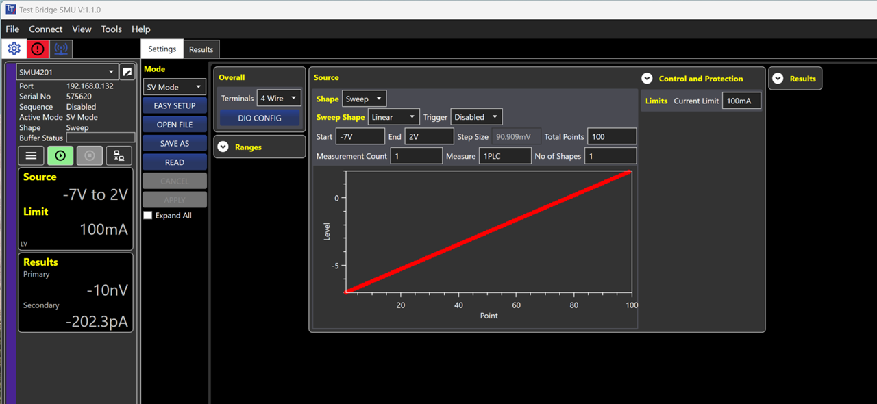
This will do a voltage sweep from -7V to +2V with 100 intermediate test voltages.

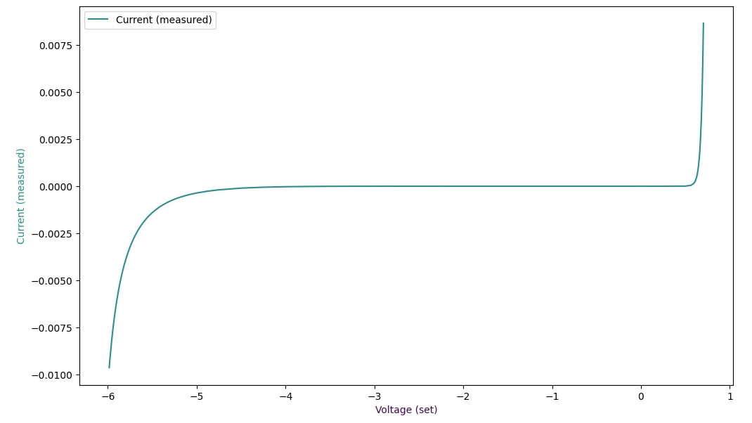
Hitting the play button starts the experiment, and after it's done we can download and display the measurement results:

image

As shown above, we were able to plot the characteristic I-V curve of the Zener diode.

My first impression is the Test Bridge SMU application can be usable for simple experiments. Unfortunately, the application is Windows only and although has some advanced features, it is not something out of ordinary. Also, I as came with programming background, I prefer controlling the instrument directly from scripts. Sunglasses

2. LAN / LXI / Jupyter Notebook

After playing around with the Test Bridge SMU application, I got back to Linux and set up a Jupyter Notebook / Lab environment for automated / scripted experiments with test instruments. Jupyter notebooks allows us to write Python code, play with data and document results interactively. Because of this I think is a great tool to do automated / scripted experiments.

To interact with the Aim-TTi SMU4201 we can use the PyVISA library, that allows controlling lab gear remotely via the VISA, SCPI and LXI standards. To connect to the instrument is easy as:

rm = pyvisa.ResourceManager()
smu_4201 = rm.open_resource("TCPIP::192.168.0.132::5025::SOCKET", write_termination = '\n',read_termination='\r\n')
smu_4201.query("*IDN?")

After this we can send various commands to the instrument as described in the SMU4000 Series Programming Manual (Issue 1) document. For example this is how we bring the SMU to Source Voltage (SV) mode:

# Reset to defaults
smu_4201.write("*CLS; *RST")
time.sleep(1)

# Configure Source Voltage (SV) mode
smu_4201.write("SYSTem:FUNCtion:MODE %s" % "SOURCEVOLTage")
smu_4201.write("SOURce:VOLTage:FIXed:LEVel %s" % "1.000 V")
smu_4201.write("SOURce:VOLTage:CURRent:LIMit %s" % "10 mA")
smu_4201.write("SOURce:VOLTage:TERMinals %s" % "4WIRe")

If we look at the voltage sweep done before, we can see that the step size is constant (~90mV) and the resolution around the breakdown and threshold voltages is a bit low. We could add more data points, but this makes the experiment slower and in the linear region we are kind of wasting buffer space.

To avoid this, with the scripted experiments I wanted to do something a bit smarter, so I came up an "adaptive sweeping" method. What this "adaptive sweeping" does is that start sweeping with a large step size (ex. 0.25 V) and based on the measured values it decreases the step size as needed:

# Turn on the output
smu_4201.write("OUTPut:STATe %s" % "ON")
time.sleep(1)

# Positive voltages
pos_idx, pos_volt_set, pos_volt_meas, pos_curr_meas \
    = adaptive_sweep(0.0, 1.0)

# Negative voltages
neg_idx, neg_volt_set, neg_volt_meas, neg_curr_meas \
    = adaptive_sweep(0.0, -7.0, -0.25)

# Turn off the output
smu_4201.write("OUTPut:STATe %s" % "OFF")

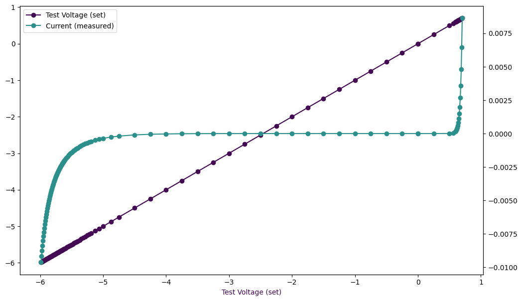
This is what the resulting graph looks like:

image

As you can see the curve is much more smooth, despite having a similar number of data points (112 vs. 100 points). This is achieved by collecting more data points where the change of measured values is faster:

image

The full Jupyter notebook can be found in the Aim-TTi-SMU4201-Zener-Diode-Characterization.ipynb gist.

To be continued! Slight smile

  • Sign in to reply

Top Comments

  • dougw
    dougw over 2 years ago +1
    Interesting that the zener "knee" is not very precise.
  • DAB
    DAB over 2 years ago +1
    Nice test. I learned very early in testing, that you want to maximize data collection where the device gets interesting.
  • jc2048
    jc2048 over 2 years ago in reply to dougw

    Yes, it's interesting.

    This is what the datasheet shows. The middle curve is the 6.2V zener. It's fairly similar if you take into account that it shows log current rather than the linear of this test with the SMU (the manufacturer would have done it with pulse tests rather than the sweep to avoid the self heating, but it doesn't look to be making too much difference up to 10mA).

    image
    With device voltages in this intermediate area (5V-7V), there's a crossover between the initial (much softer) zener effect and the (hard) avalanching that it then runs into. For a power device, that crossover is evidently pushed up to higher currents. Vishay have chosen a test current of 60mA for that one to get the test up to the area where the diode might be considered to be sensibly 'regulating' the voltage on the avalanche.

    In contrast, these next curves come from the Nexperia datasheet for the BZX84. That's a 200mW part, so they're only going up to 10mA, but they've taken the current right down so you can see the shapes much better than you normally would on a device datasheet. For this lower power device, the changeover for the 6V2 part is at a much lower current, and it's 'regulating' moderately well at their chosen test current of 5mA.

    image

    • Cancel
    • Vote Up 0 Vote Down
    • Sign in to reply
    • More
    • Cancel
  • DAB
    DAB over 2 years ago

    Nice test.

    I learned very early in testing, that you want to maximize data collection where the device gets interesting.

    • Cancel
    • Vote Up +1 Vote Down
    • Sign in to reply
    • More
    • Cancel
  • genebren
    genebren over 2 years ago in reply to dougw

    I am not sure, but you might be fooled by the axis, which is flipped from the normal presentations. The measure voltage is on the Y-axis (left), the set voltage is on the X-axis, while the measured current is on the secondary Y-axis (right). So the knee is quiet sharp, but laying on its side.

    • Cancel
    • Vote Up 0 Vote Down
    • Sign in to reply
    • More
    • Cancel
  • dougw
    dougw over 2 years ago

    Interesting that the zener "knee" is not very precise.

    • Cancel
    • Vote Up +1 Vote Down
    • Sign in to reply
    • More
    • Cancel
element14 Community

element14 is the first online community specifically for engineers. Connect with your peers and get expert answers to your questions.

  • Members
  • Learn
  • Technologies
  • Challenges & Projects
  • Products
  • Store
  • About Us
  • Feedback & Support
  • FAQs
  • Terms of Use
  • Privacy Policy
  • Legal and Copyright Notices
  • Sitemap
  • Cookies

An Avnet Company © 2025 Premier Farnell Limited. All Rights Reserved.

Premier Farnell Ltd, registered in England and Wales (no 00876412), registered office: Farnell House, Forge Lane, Leeds LS12 2NE.

ICP 备案号 10220084.

Follow element14

  • X
  • Facebook
  • linkedin
  • YouTube