


Introduction
This is a set of tests carried out on the Tektronix MDO Demo Board 1 with the 3 Series MDO concentrating on the serial decoding functions within the oscilloscope. The demonstration board has 5 serial signal examples.
- UART / RS232
- CAN Bus (CAN_H and CAN_L)
- FlexRay
- I2C (I2C_CLK and I2C_Data)
- LIN Bus
- MIL-STD-1553
- MIPI D-PHY (MIPI_Data and MIPI_CLK)
- SPI Bus (SPI_CLK, SPI_SS-1 and SPI_MOSI-1)
- USB (USB_LS, USB_FS and USB_HS)
The 3 Series MDO does not have demonstration setups for all of these functions, so some of them you will have to put up with my attempts to capture the signals. All of the demonstration setups use the analogue channels to capture the signals.
RS232 Bus Decoding
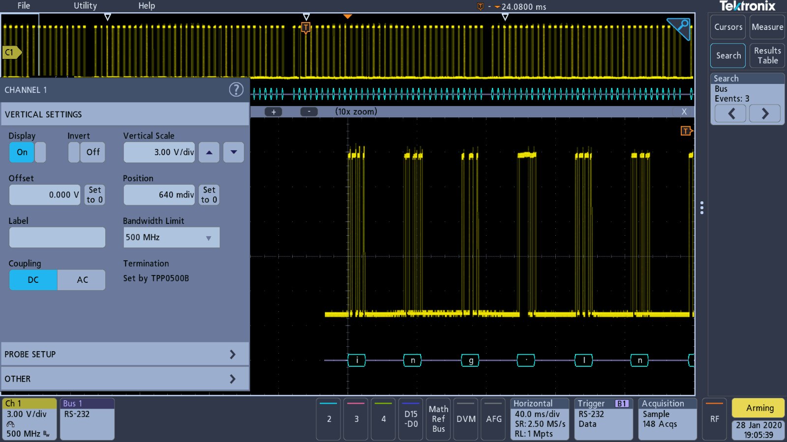
This signal has a 9600 baud rate and the data format is one start bit, eight data bits and no parity. A setup exists for this signal within the demonstration functions.

The setup works well and captures the data based upon a data trigger looking for the 'T' character.
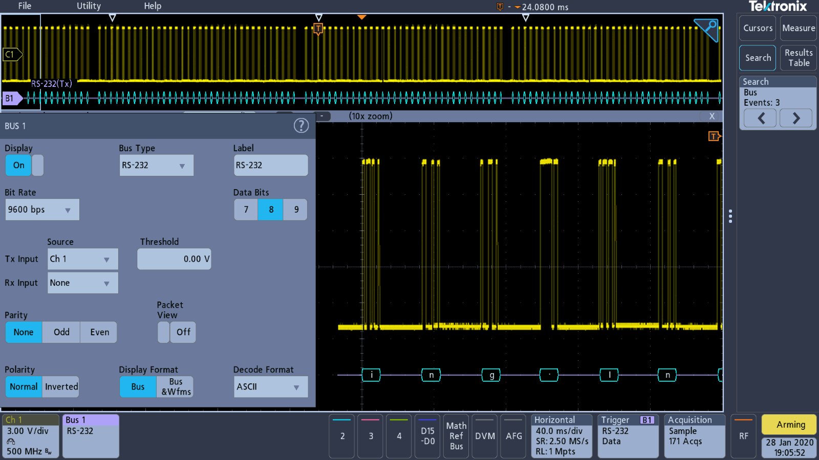
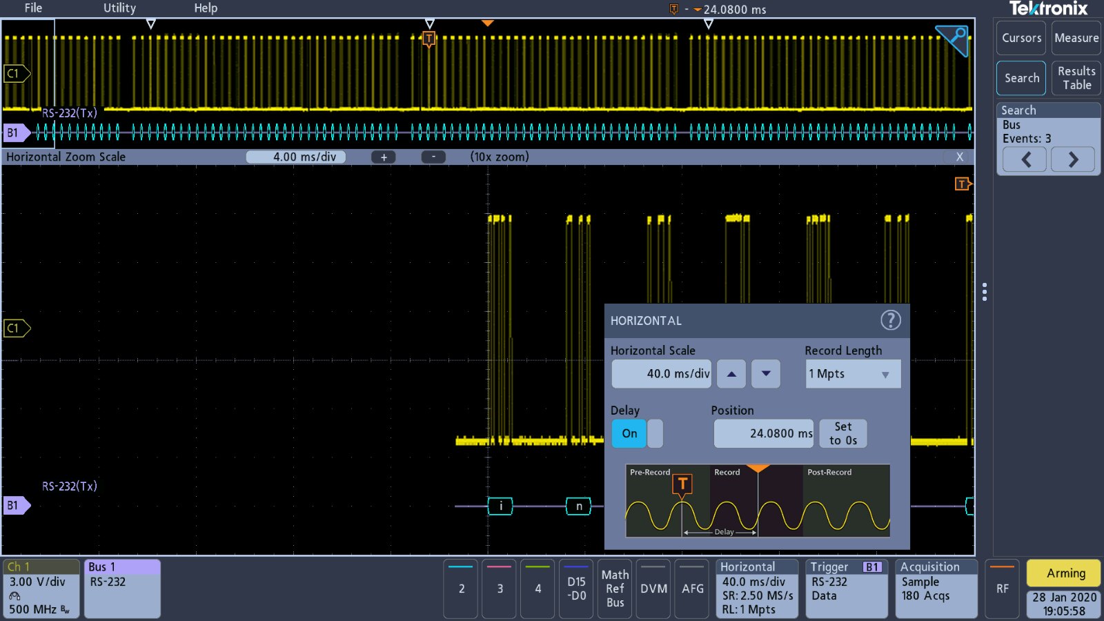
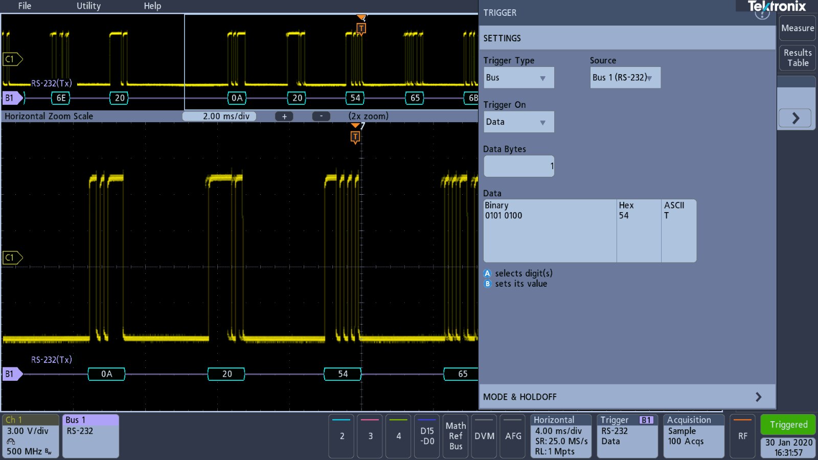
| {gallery} RS232 Signal Capture Setup |
|---|
Vertical Settings for Channel 1 |
Bus Settings for RS232 decoding |
Timebase settings |
Data acquisition settings |
Trigger settings |

Tektronix have embedded the message "Tektronix Enabling Innovation" within the data of the RS232 signal. This message cab be found utilising the search function of the oscilloscope. The search function contains a button to copy over the settings from the trigger menu.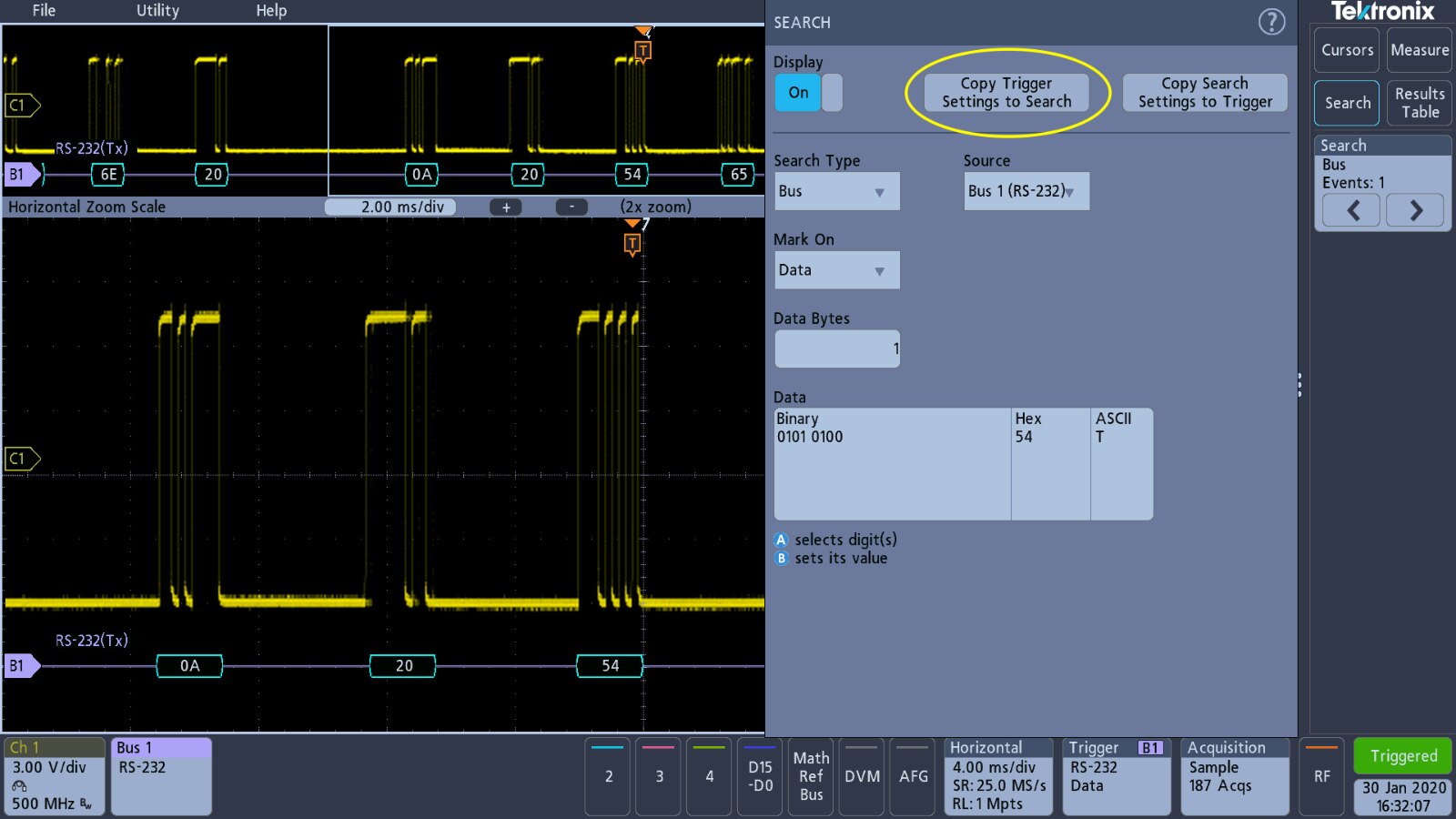
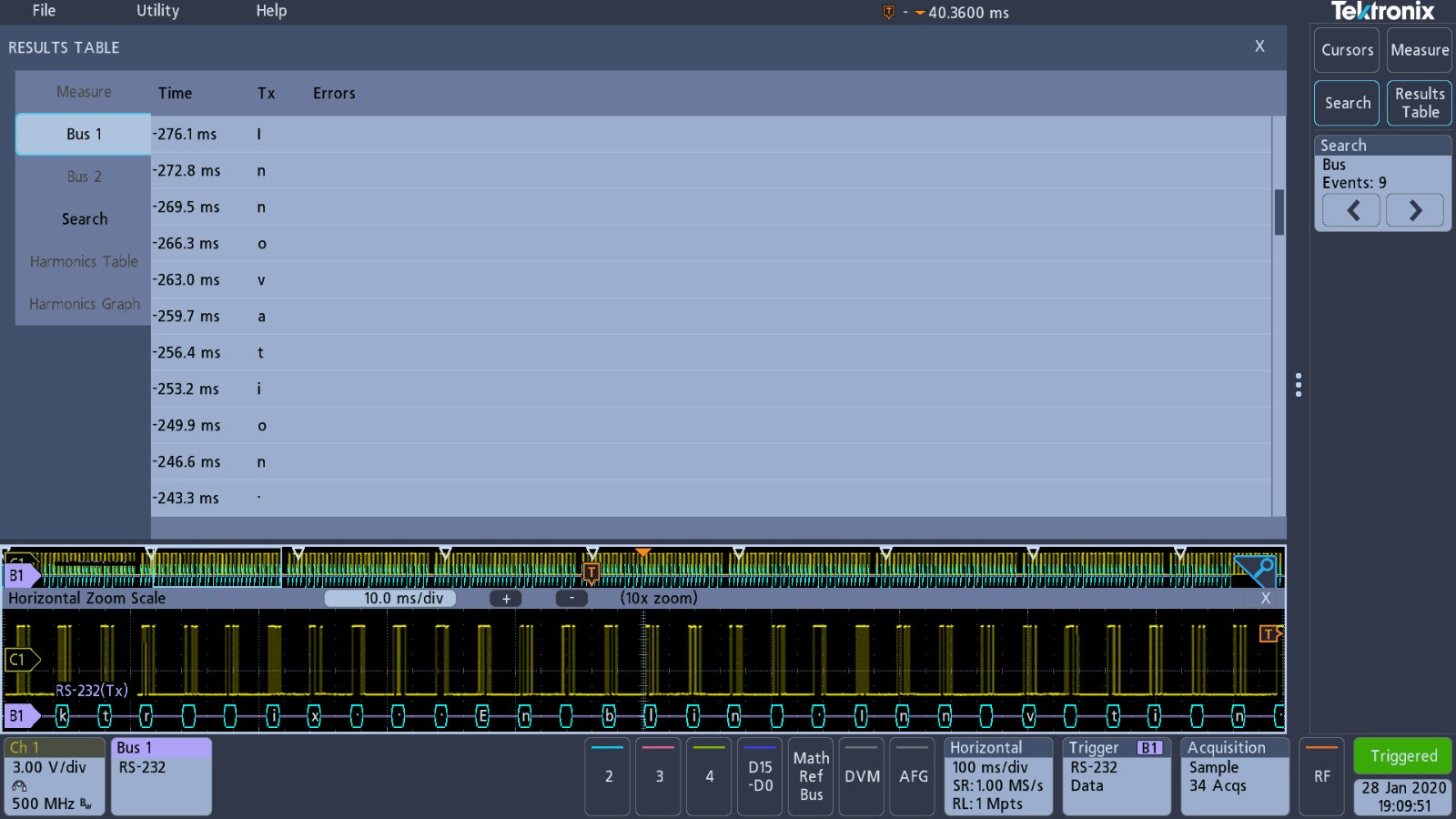
This allows the message to be found and manipulating the timebase position or searching on different characters allows the message to be read. Activating the results table displays the message, or it can be read within the decoding on the screen capture.
| {gallery} RS232 Message |
|---|
'Tektronix' word captured |
'Enabling' word captured |
'Innovation' word captured |
'Tektronix' word captured on screen decoding |


With the results table displayed, the contents can be saved to a CSV file for further data manipulation and analysis. As with screensave functions, the menu offers a default filename and automatically finds the USB drive.


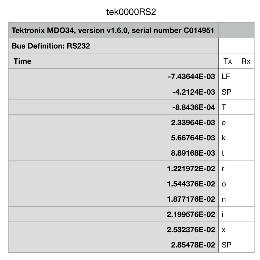
The CSV file exported basically follows the structure of the data table from the oscilloscope. The video below goes through manually setting up the 3 Series MDO to capture and decode the RS232 signal and then use the search function to find each word.
Alternative to using the search function on this occasion is to enable packet view on the bus settings window.

The data packets are then displayed on the oscilloscope revealing the full message.

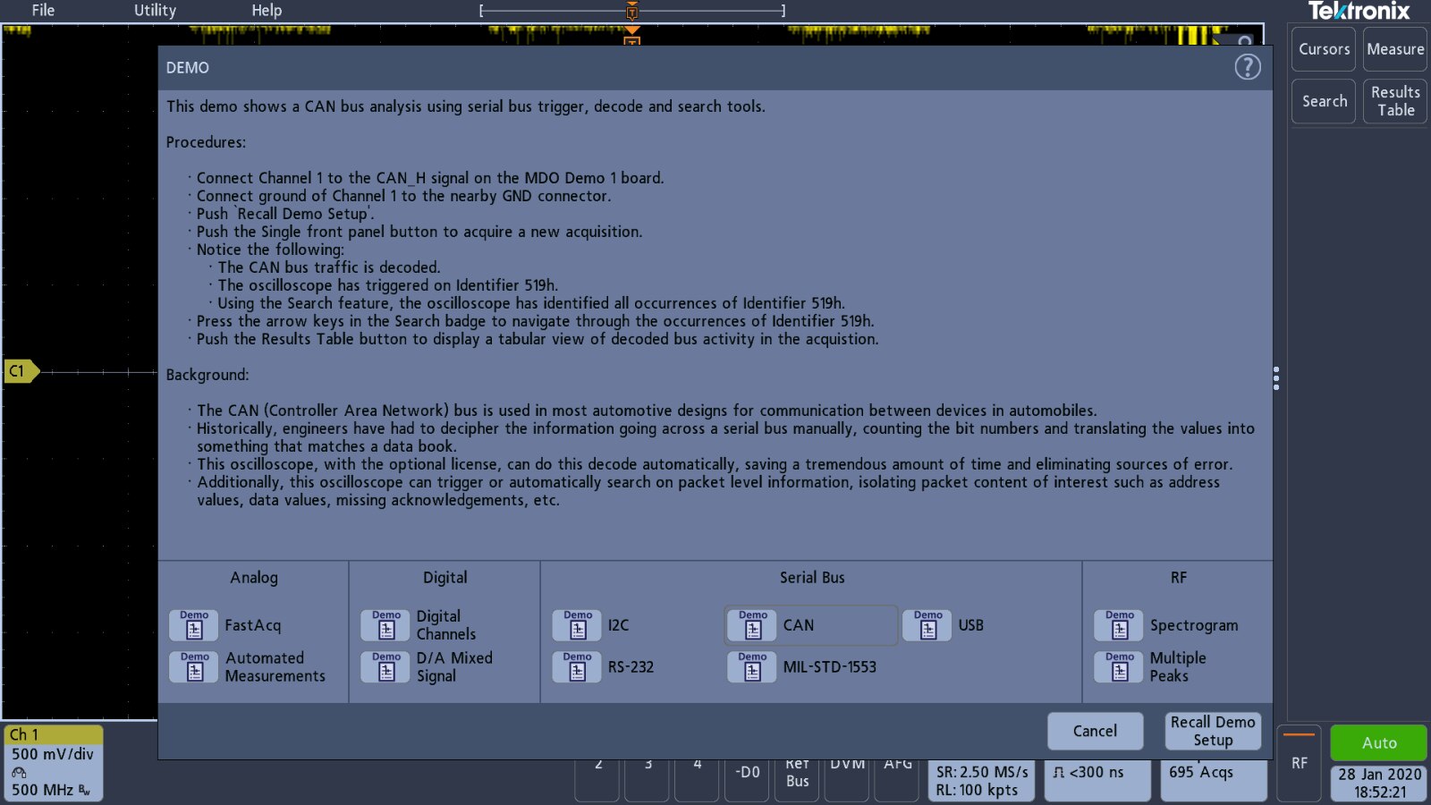
CAN Bus Decoding
This is another serial signal that has a setup built into the demonstration function.
Whilst the demo board has CAN_H and CAN_L signals only the CAN_H has a demonstration setup.
| {gallery} CAN_H Signal Capture Setup |
|---|
Vertical channel settings |
Bus settings for CAN_H decoding |
Timebase settings for CAN |
Trigger settings for CAN |
Initial failure to decode CAN signal |
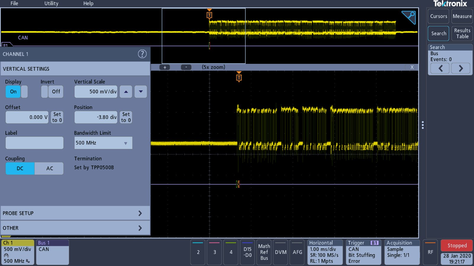

As can be seen from the last screenshot in the gallery above, the demo settings for the bus failed to decode the CAN signal. It took me a little while to figure out what was wrong with this. I tried several of the trigger options available and did manage to trigger on the 'Bit Stuffing Error' to some extent.

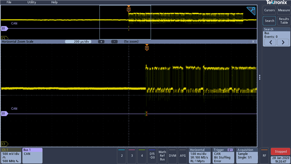
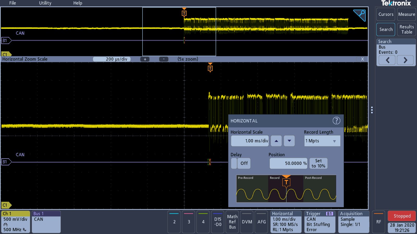
I am not quite sure why I thought of it, but I decided to carry out some measurements on the CAN bus signal and that eventually led me to discovering the triggering issue.
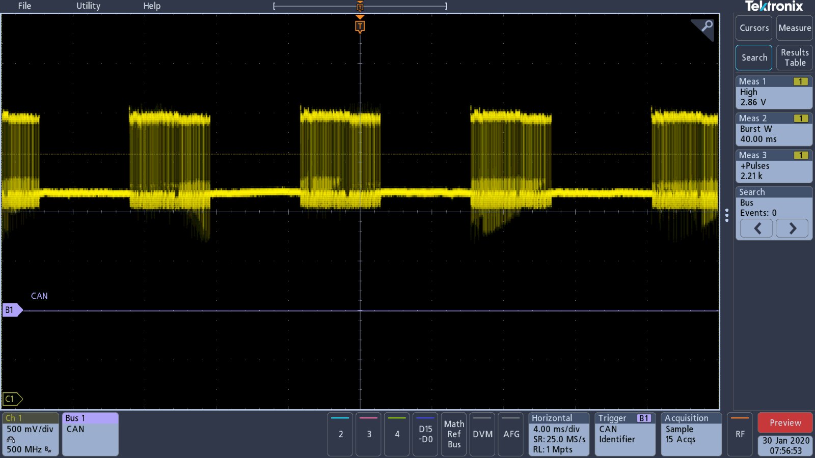
The measurement that came of interest to me was the voltage high measurement that ranged between 2.86 V above and 2.94 V in the second capture below.

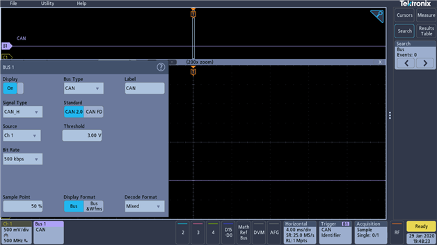
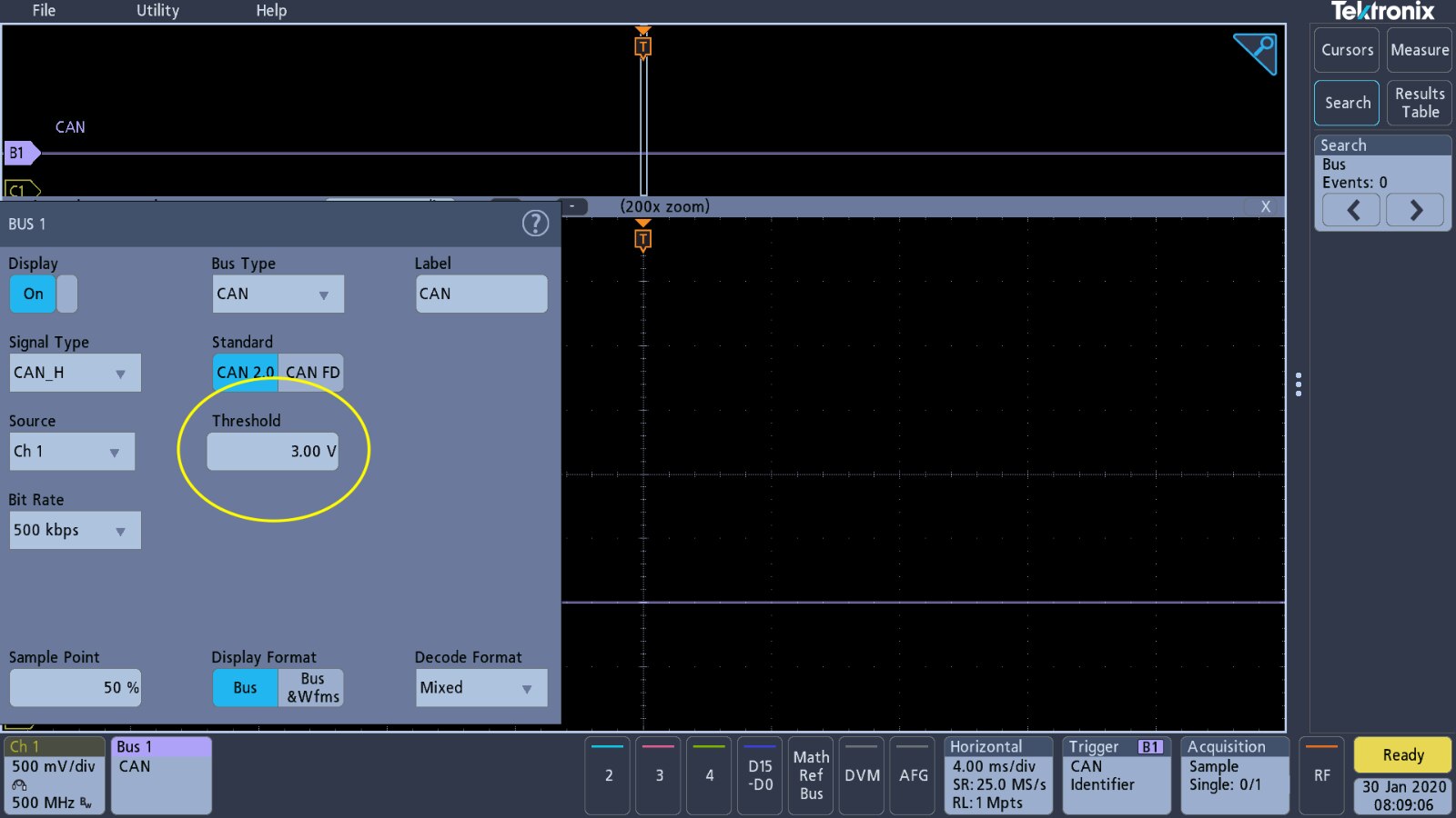
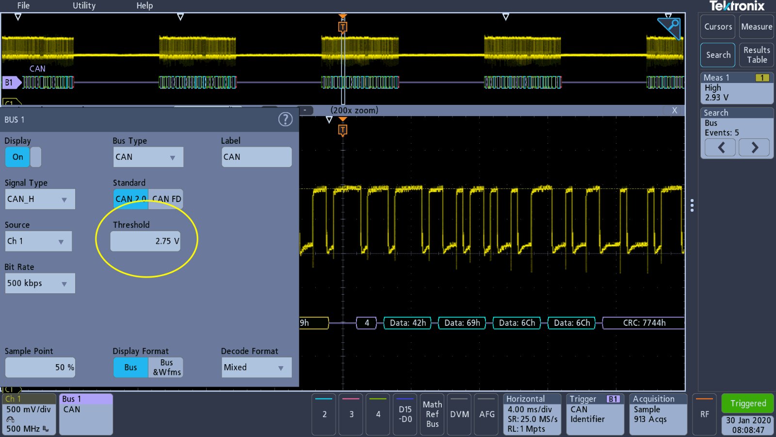
Looking at the CAN Bus settings, the threshold value for the signal was found to be set to 3.00 V, just slightly above the actual voltage being measured. Lowering this threshold voltage allowed the oscilloscope to trigger on the demo settings and decode the signal. I do not know enough about CAN to understand if it is the demonstration signal that is slightly out or the setup settings for the threshold are in the wrong.
| {gallery} CAN Bus Threshold |
|---|
Original threshold setting for CAN |
Threshold setting reduced |
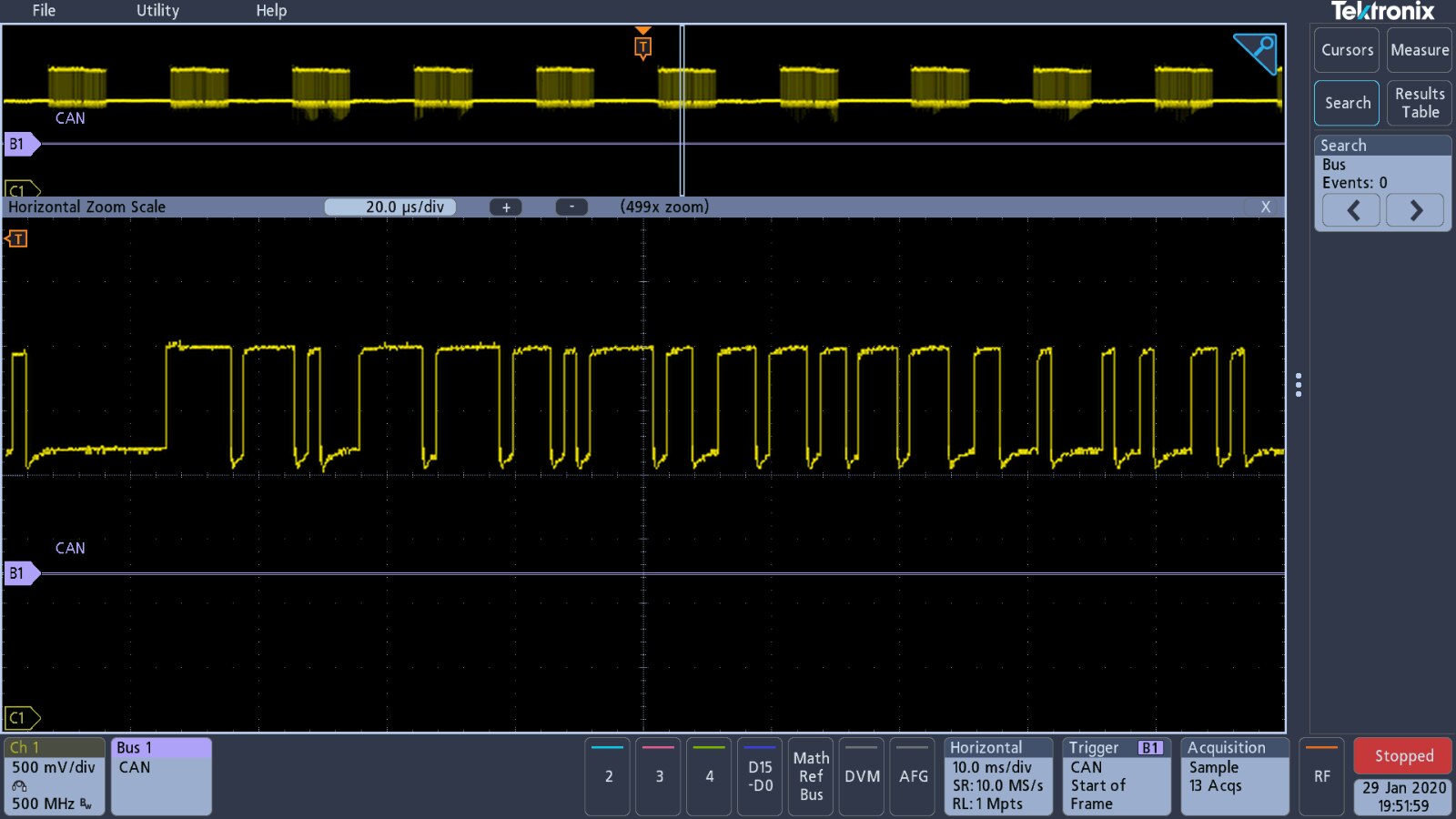
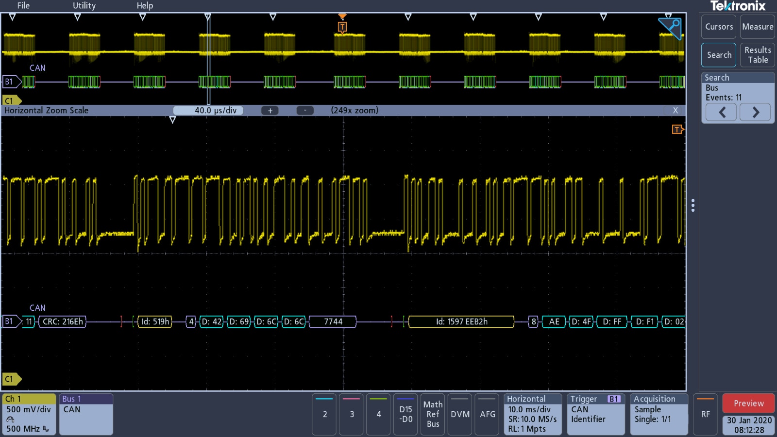
CAN bus triggered and signals decoding |
CAN bus signal event search |
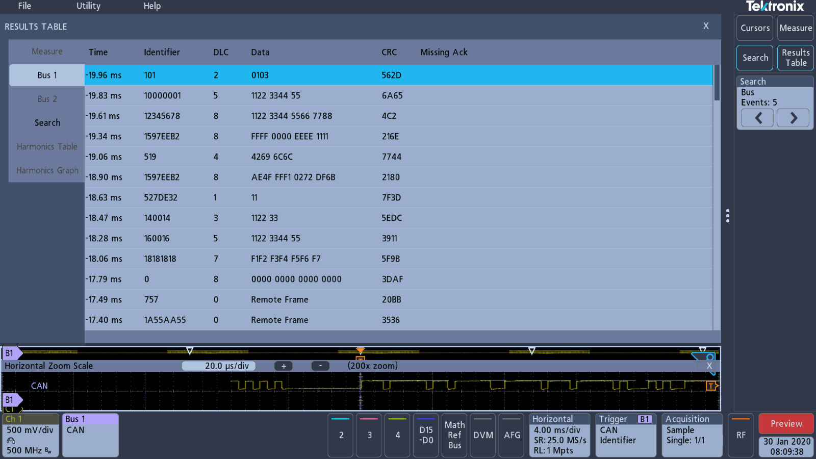
CAN bus result table from search function |

FlexRay Bus Decoding
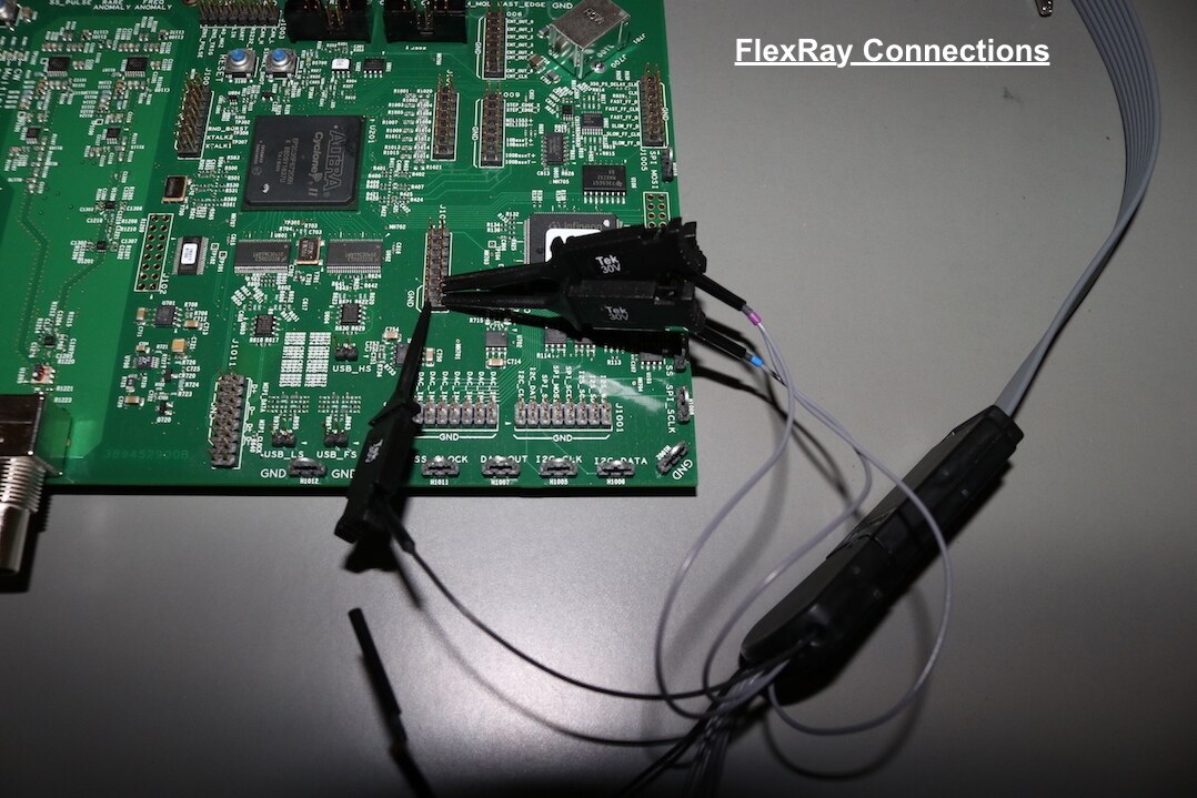
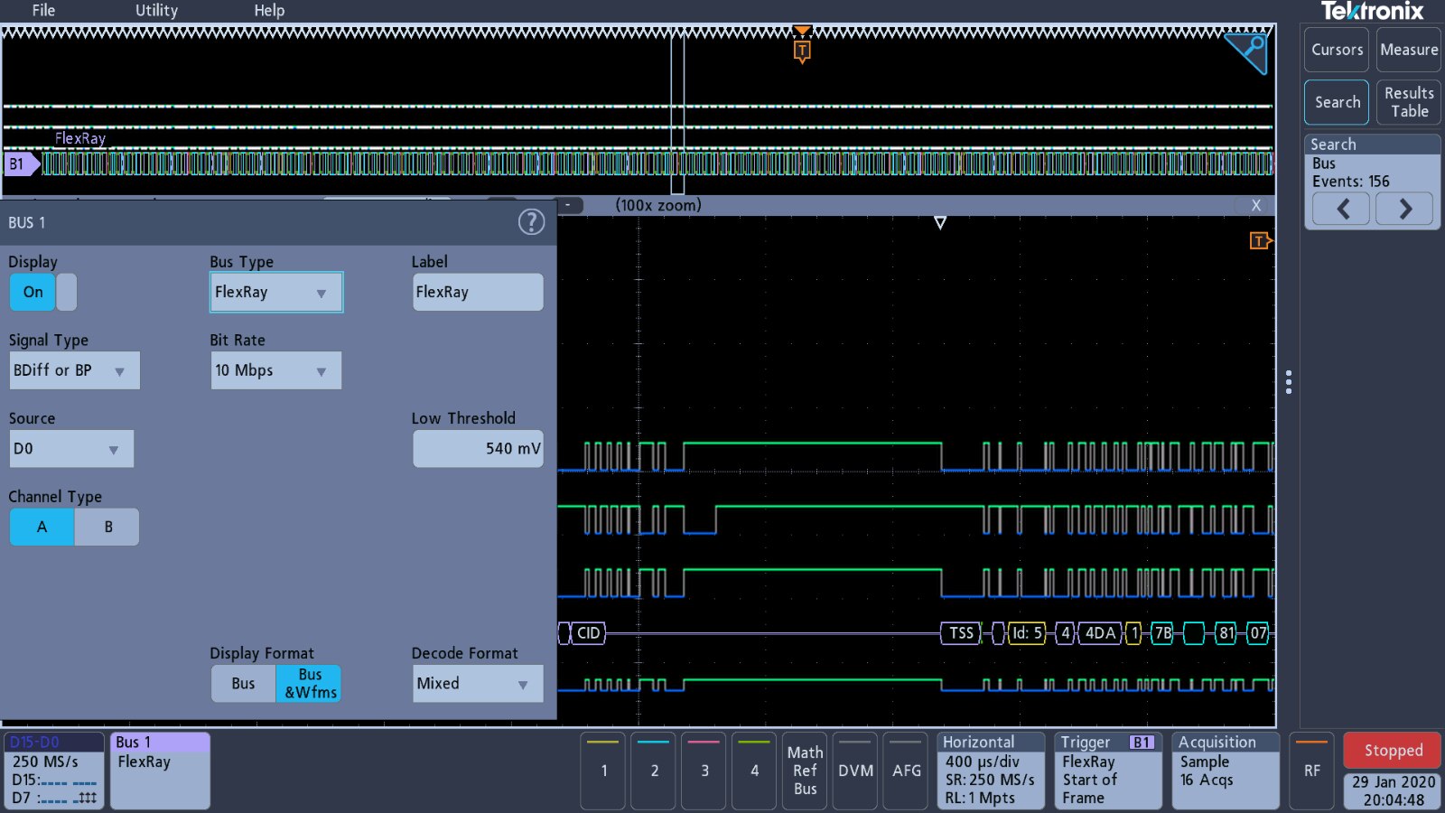
I have never heard of a FlexRay bus, it appears to be a more modern alternative to a CAN bus. Nonetheless, there is a decode option within the 3 Series MDO for this signal and the demo board has a signal available. There is no demonstration setup for this signal, so I decided to go my own way and utilise the digital signal inputs for this test.
FlexRay on National Instruments
| {gallery} FlexRay Bus Signal Capture Setup |
|---|
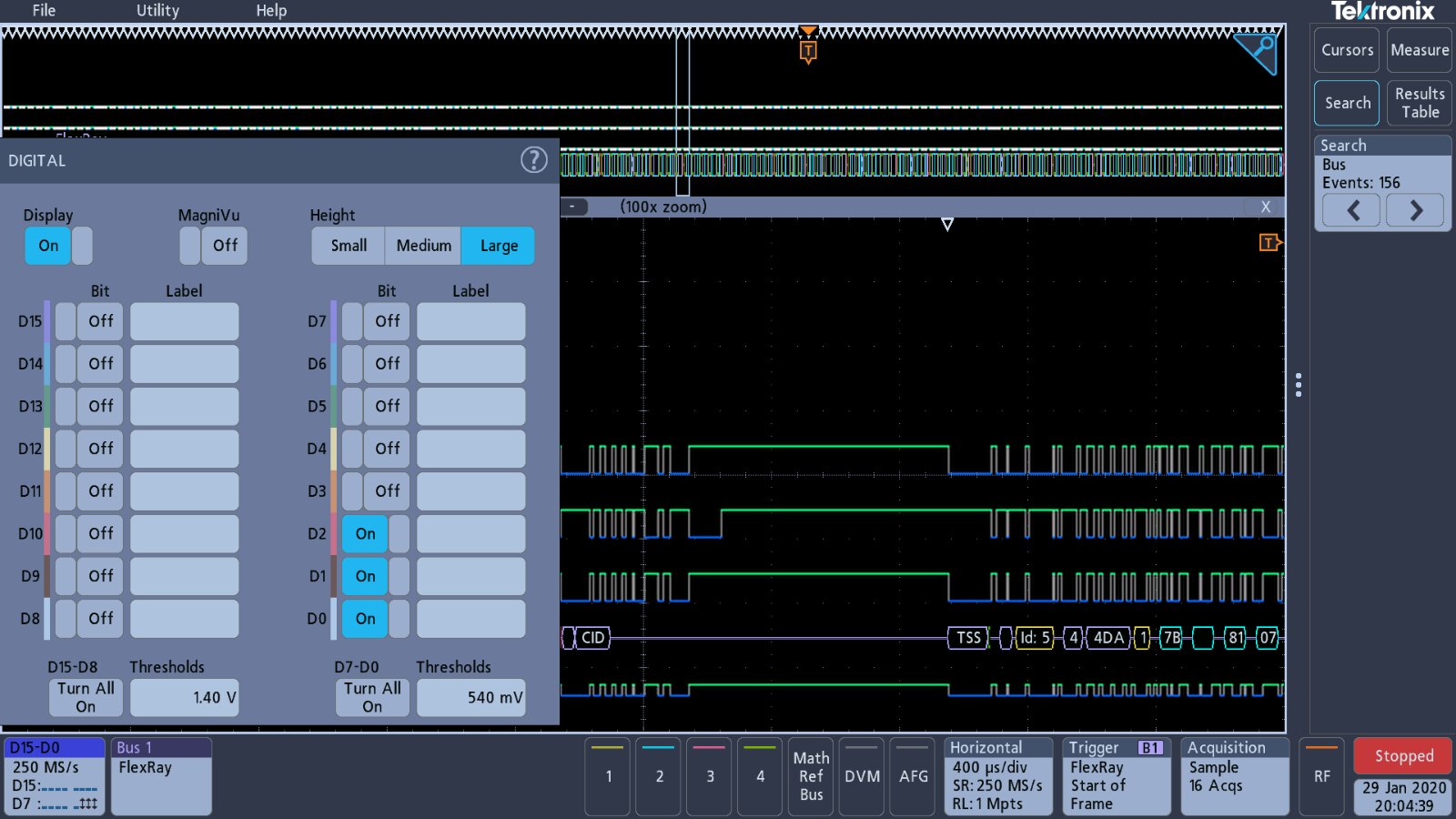
Digital input settings |
Bus decoding settings for FlexRay |
Timebase settings |
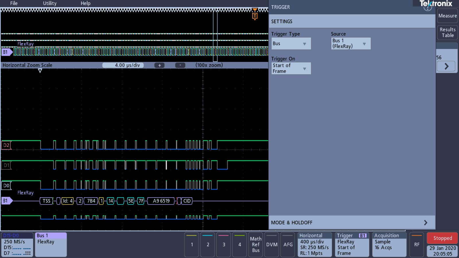
Trigger settings |
FlexRay signal decoded |


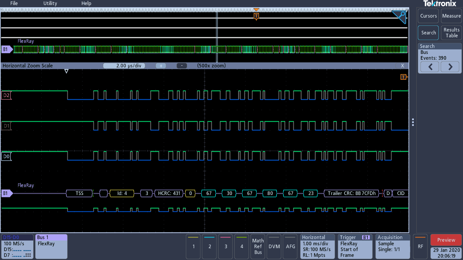
Zoomed in to capture one frame of the FlexRay signal;
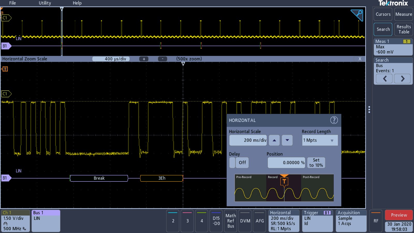
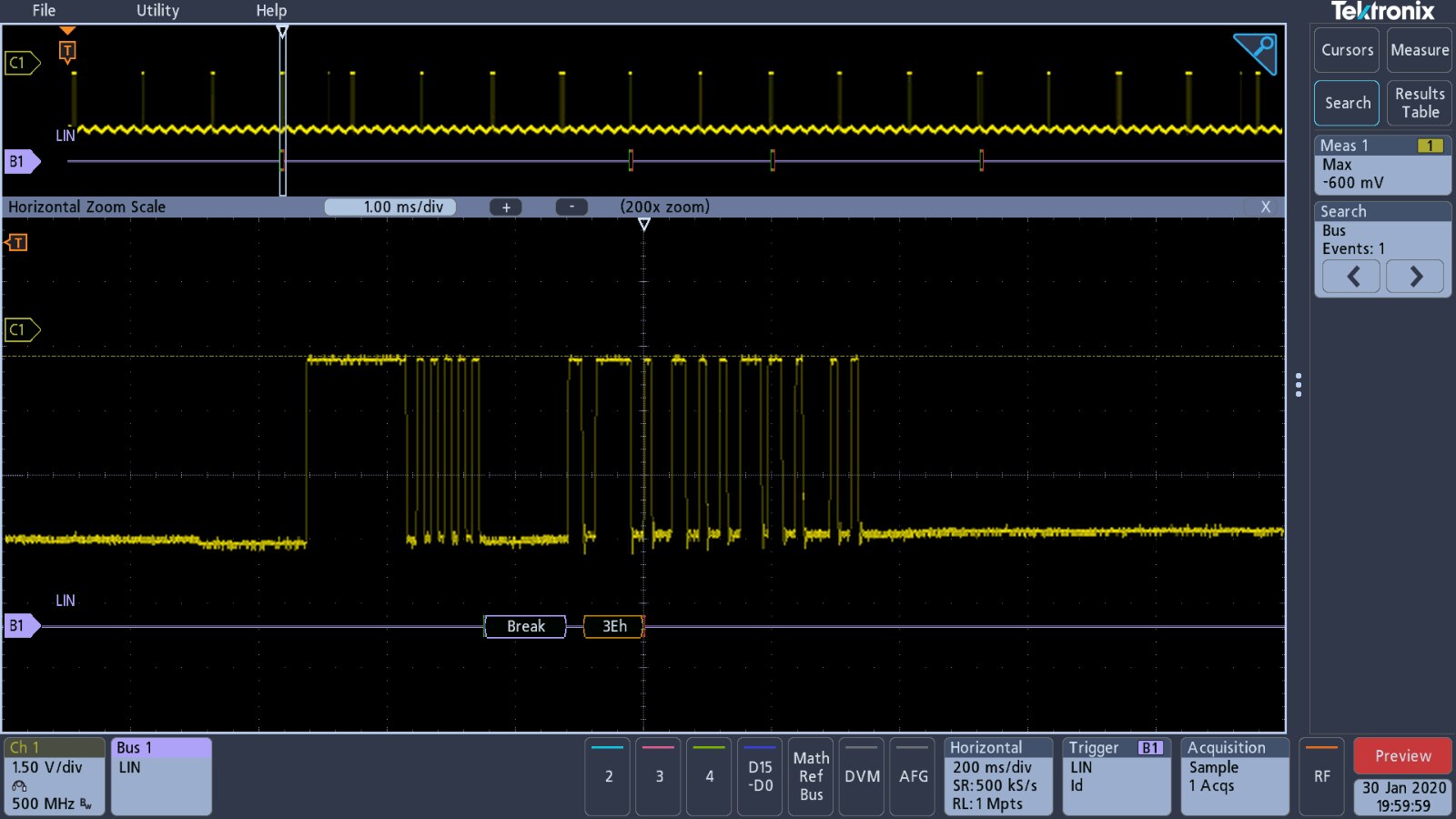
LIN Bus decoding
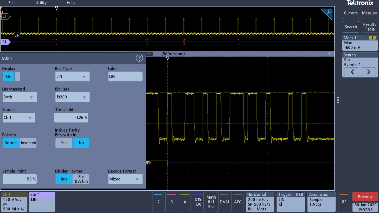
This is another bus that is available on the demo board and can be decoded by the 3 Series MDO, but does not have a demonstration setup available for, so is again subject to my rumblings on the controls of the scope.
| {gallery} LIN Bus Signal Capture Setup |
|---|
Vertical channel settings for LIN bus |
LIN Bus settings |
Timebase settings for LIN Bus |
Trigger settings for LIN Bus |
Search Settings for LIN Bus |


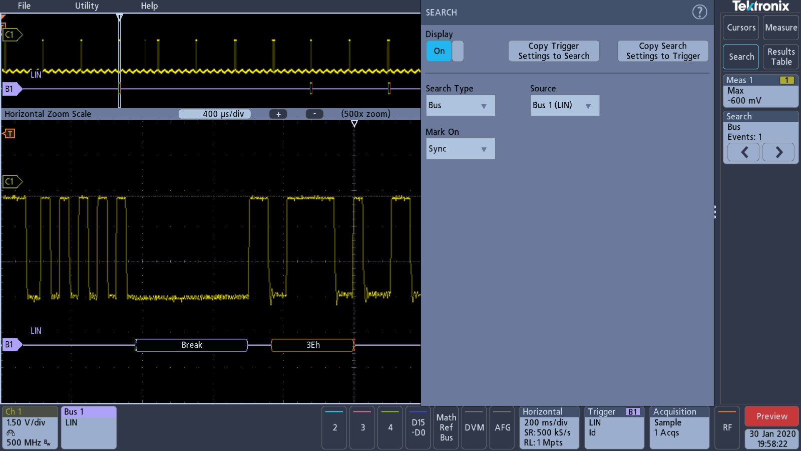
I had no idea what to search for on the LIN Bus capture, so the findings are a little weak.
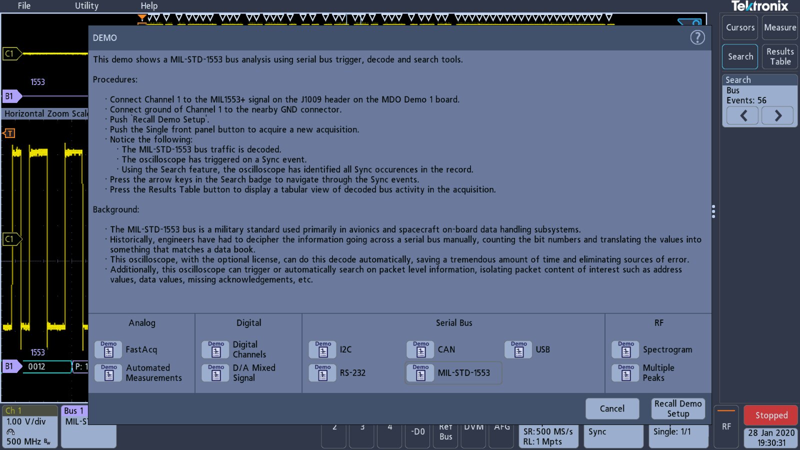
MIL-STD-1553 Bus Decoding
This time we are back to a demonstration setup for this particular standard, so the results should be more reliable. Unlike a lot of the signals that are found on test loops situated around the edge of the demo board, this signal is on one of the internal headers and I need the micro-hooks on the probes to make the connections, to avoid shorting anything out.
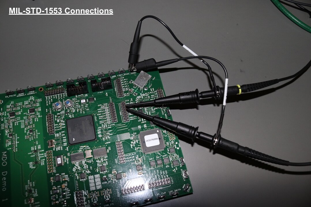
| {gallery} MIL-ST-1553 Bus Signal Capture Setup |
|---|
Vertical Channel Settings |
Bus Settings for MIL-ST-1553 |
Timebase settings |
Trigger settings |
Data acquisition settings |
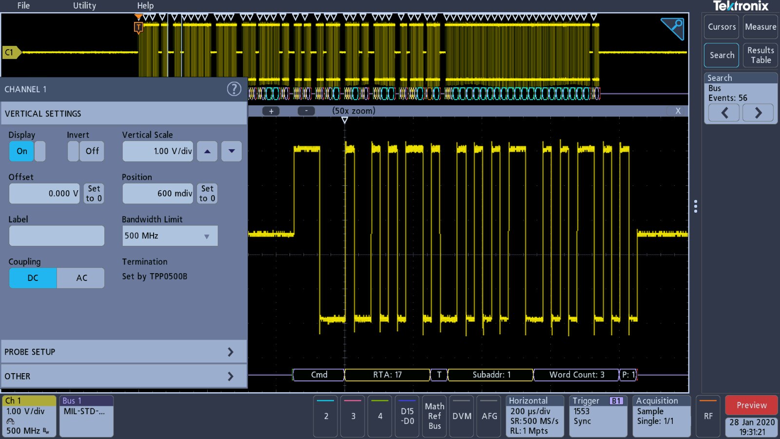
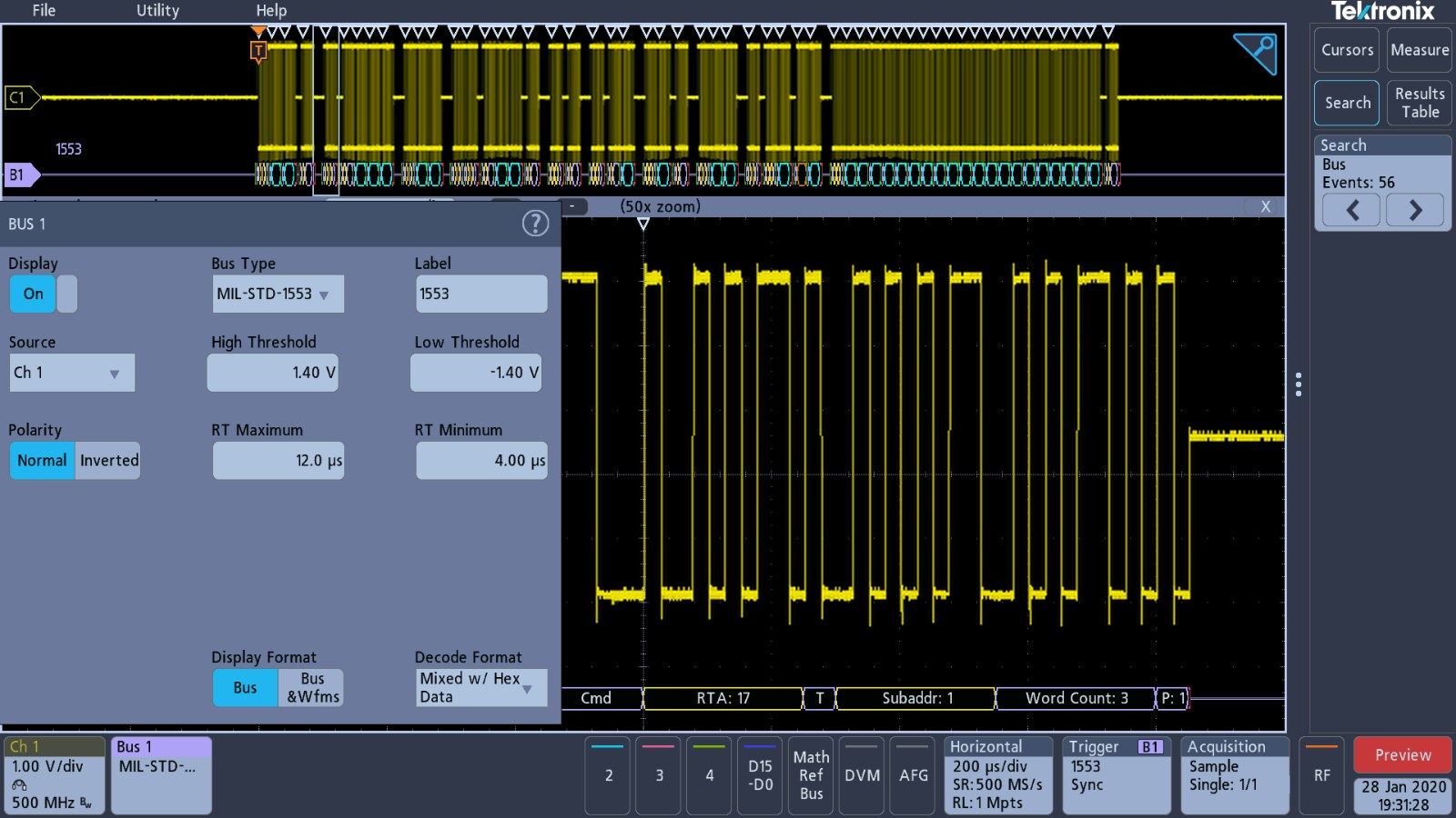

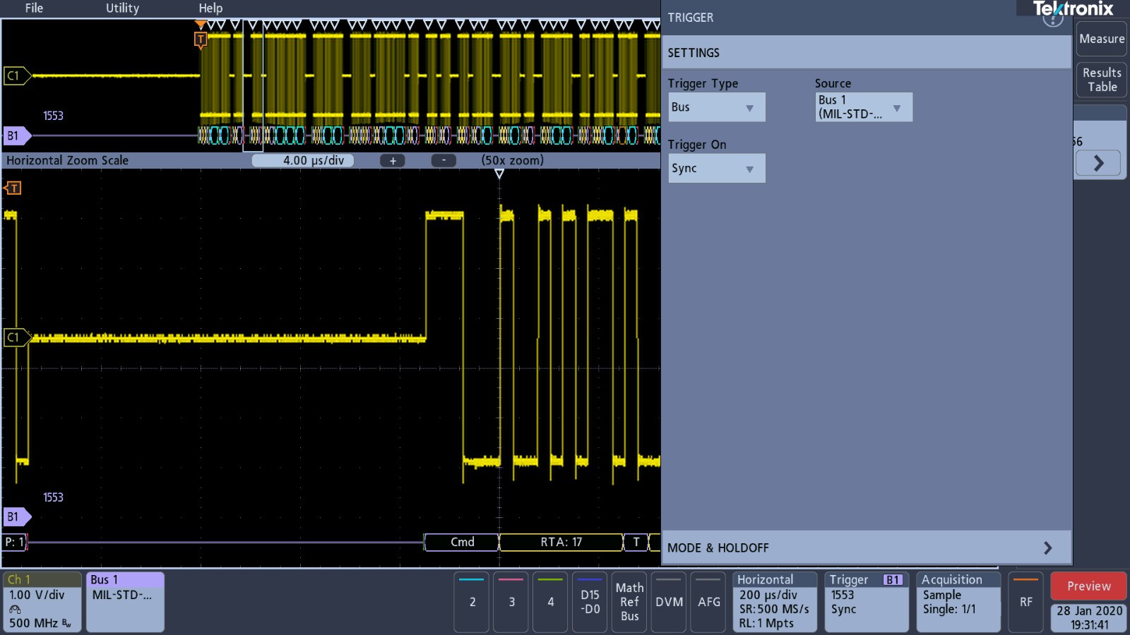

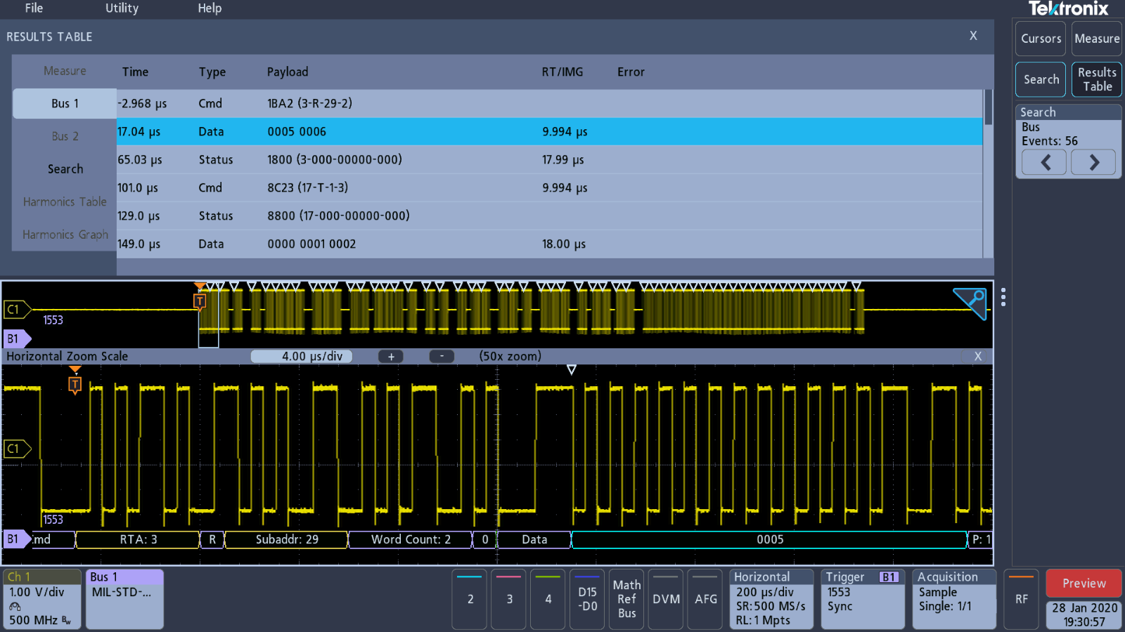
The demonstration setup meant that there were no problems capturing and decoding the signal.

As with the other signals a look at the results table provides more data for analysis and potential to export to a 'CSV' file.
SPI Bus Decoding
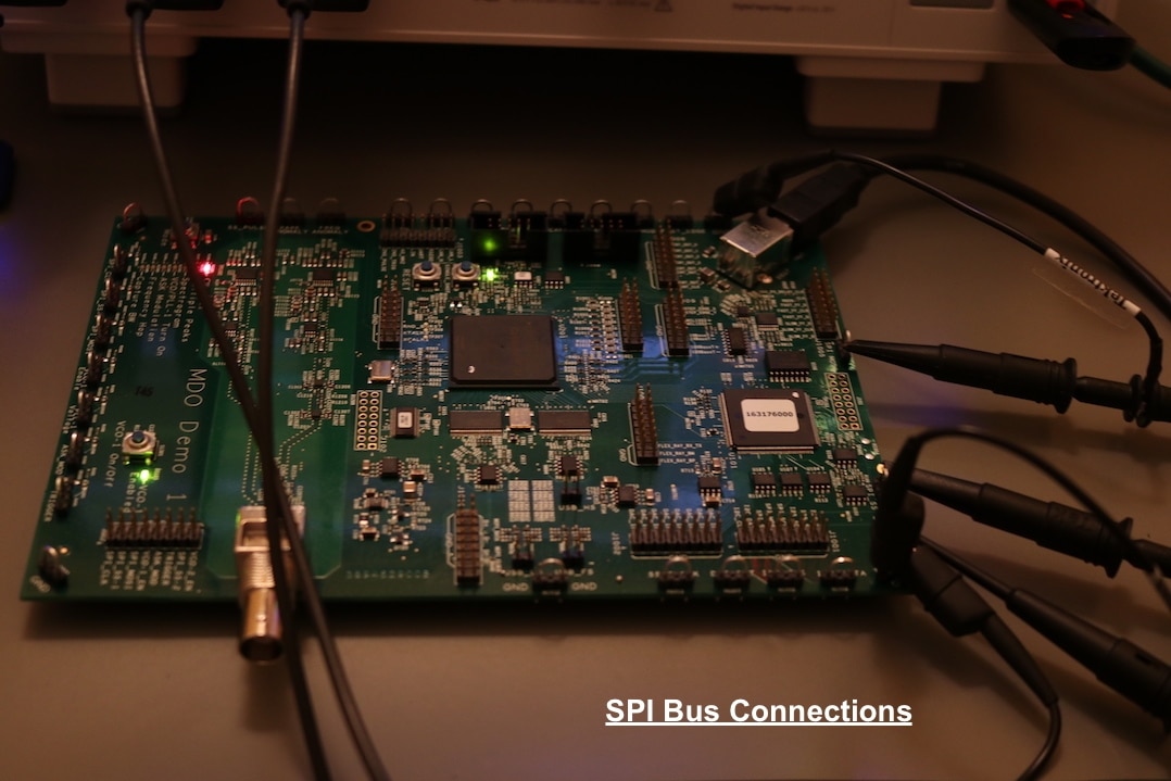
Back to a signal that has no demonstration setup in the oscilloscope. There are three signals for the SPI Bus requiring three analogue channels to be put into use.
| {gallery} SPI Bus Signal Capture Setup |
|---|
Vertical channel settings for SPI |
Bus settings for SPI |
Timebase settings for SPI |
Trigger settings for SPI |
Data acquisition settings for SPI |
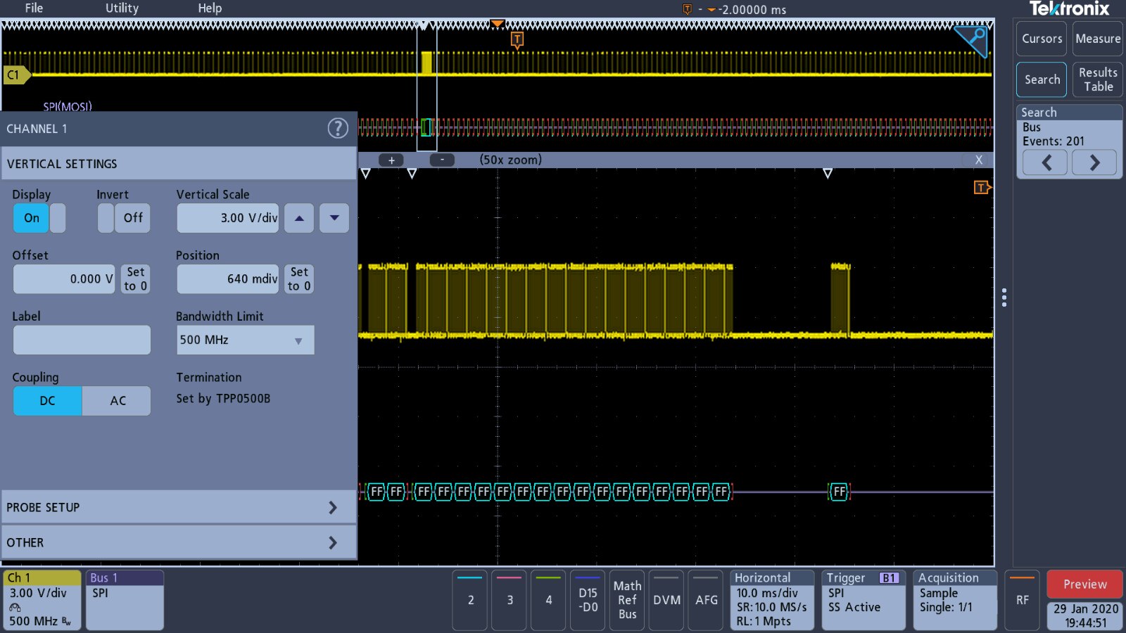
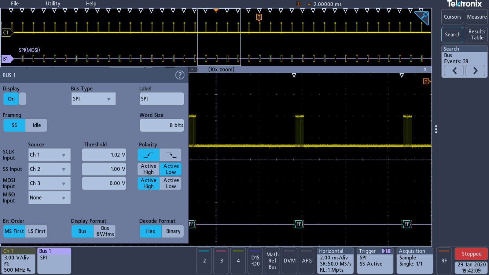

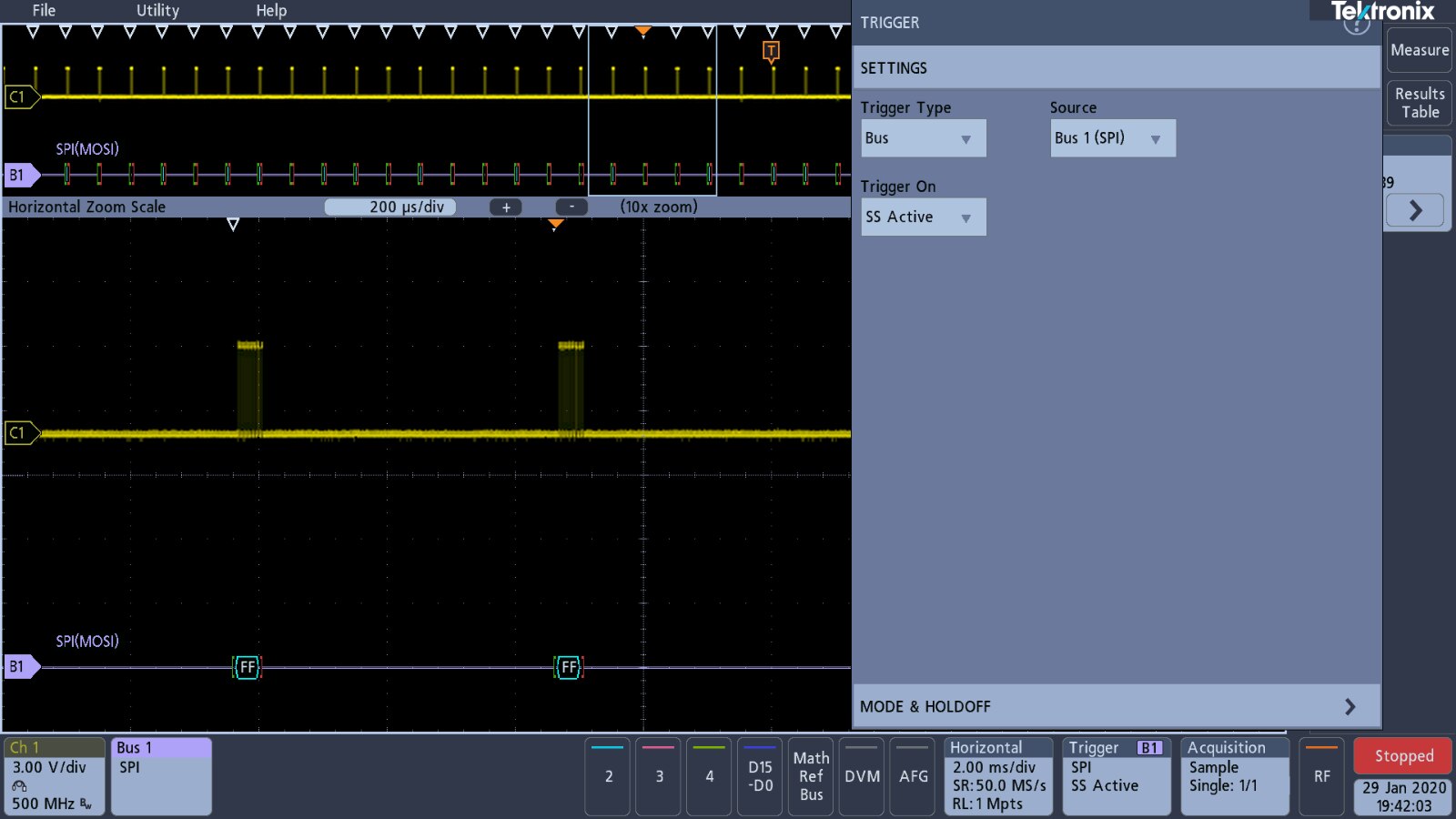
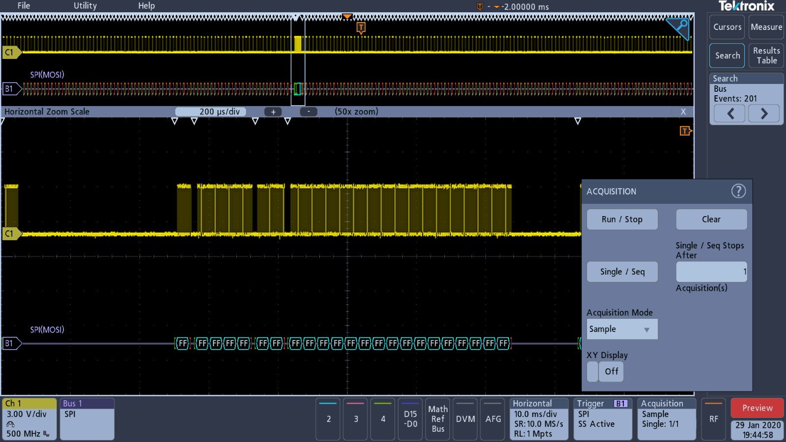
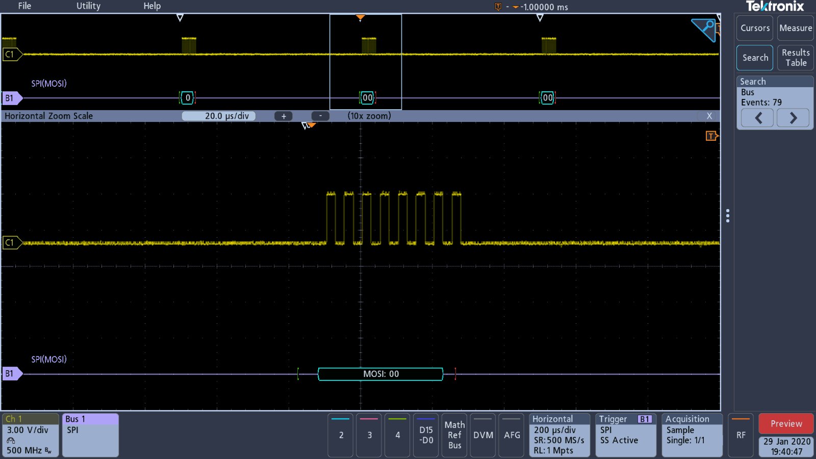
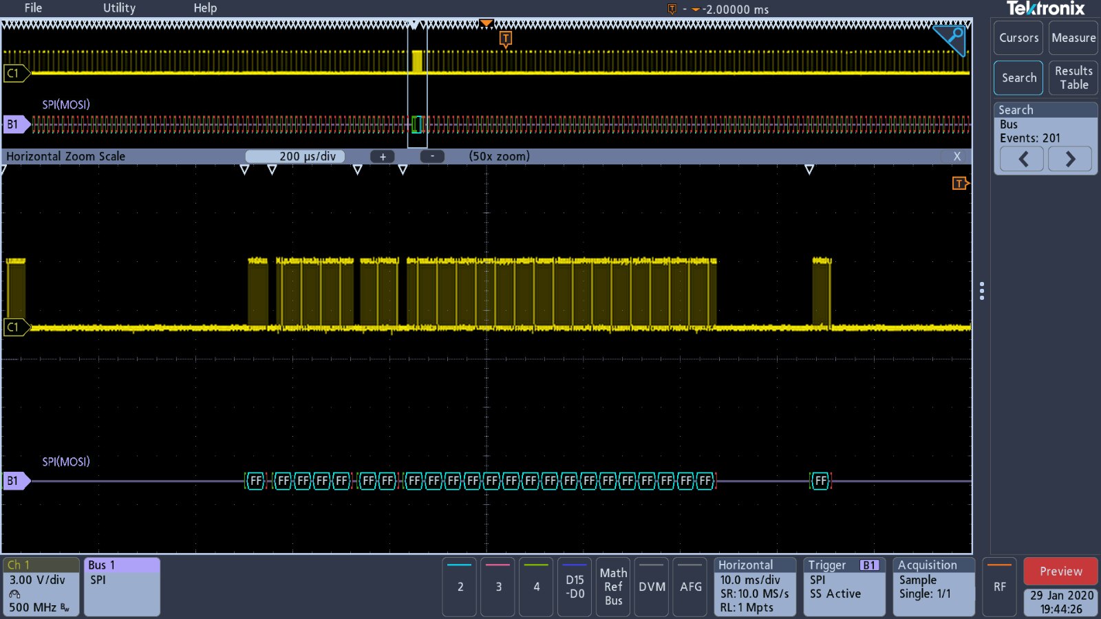
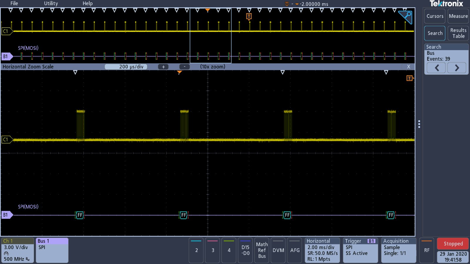
SPI is a bus that I have heard of before, but have no real experience with so all I could manage to capture was a bunch of 'FF's or '00's.
| {gallery} SPI Signal capture |
|---|
SPI Pulse Trace Capture |
SPI '00' event capture 1 |
SPI '00' event capture 2 |
SPI 'FF' event capture 1 |
SPI 'FF' event capture 2 |
SPI 'FF' event capture 3 |


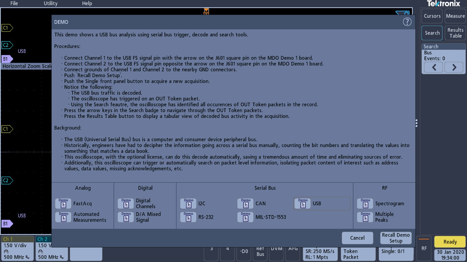
USB Bus decoding
There are three USB signals available on the demo board, low, full and high speed signals. Only the FS signal has a demonstration setup on the oscilloscope and although trying, it was the only one I was able to capture. Only the 1 GHz bandwidth version of the 3 Series MDO has the ability to capture the high speed USB signal.
| {gallery} USB Bus Signal Capture Setup |
|---|
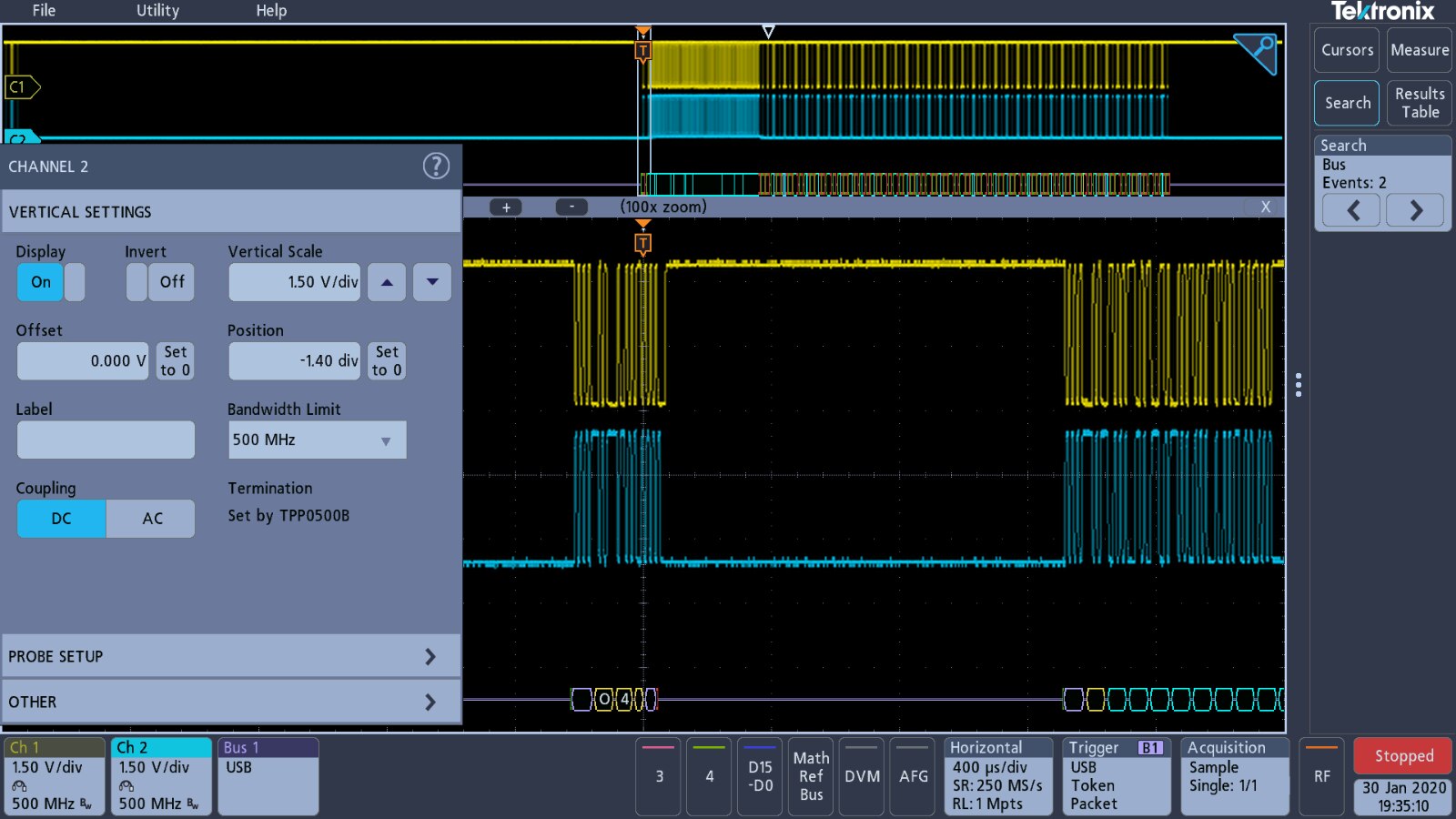
Channel 1 vertical settings |
Channel 2 vertical settings |
Bus settings for Full Speed USB |
Time base settings for Full Speed USB |
Trigger settings for Full Speed USB |
Data acquisition settings for Full Speed USB |
Event Search Settings for Full Speed USB |

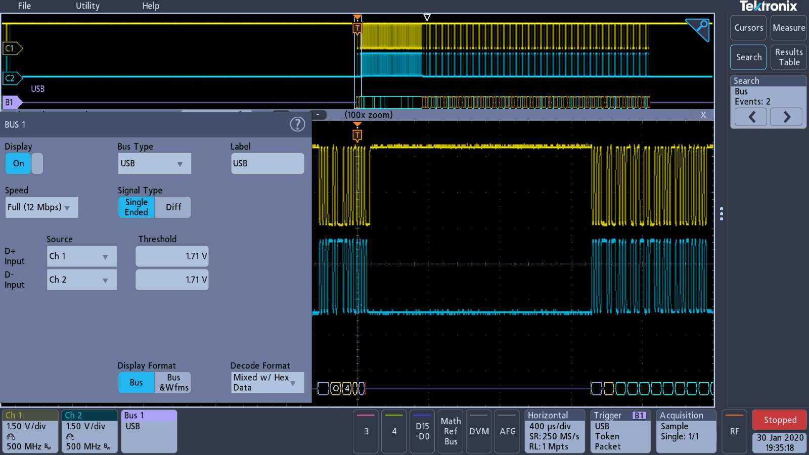


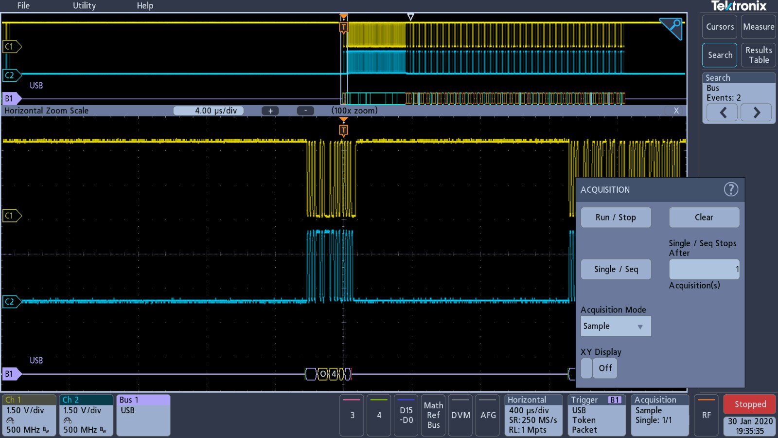
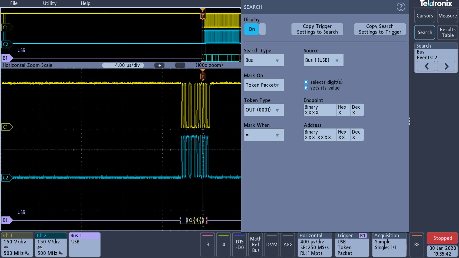
The signal is triggered on an 'Out' token event, however, it doesn't look like I have actually captured and displayed the token on the screenshot, unless it is displayed as the 'O' block preceding the '4'.
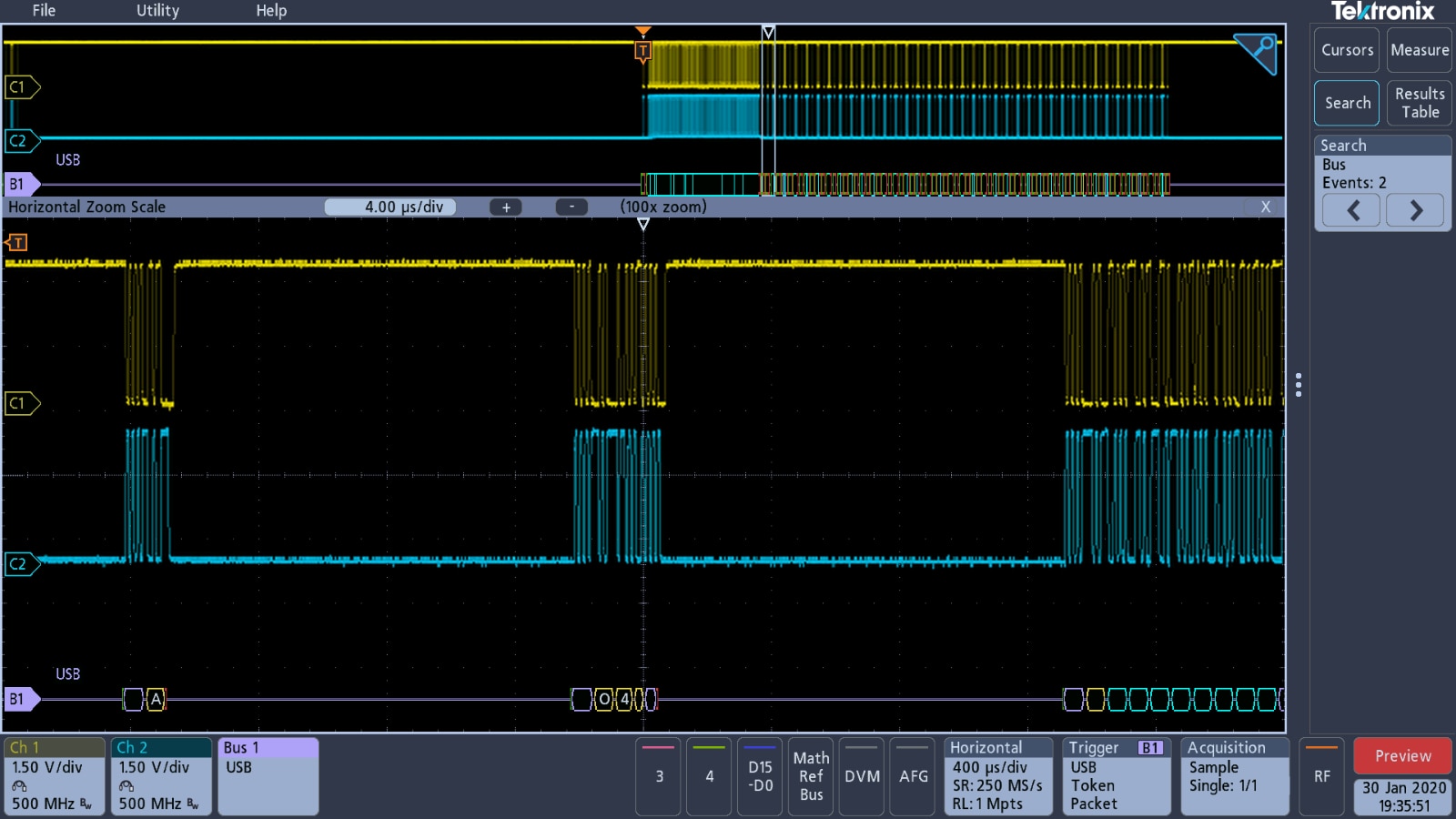
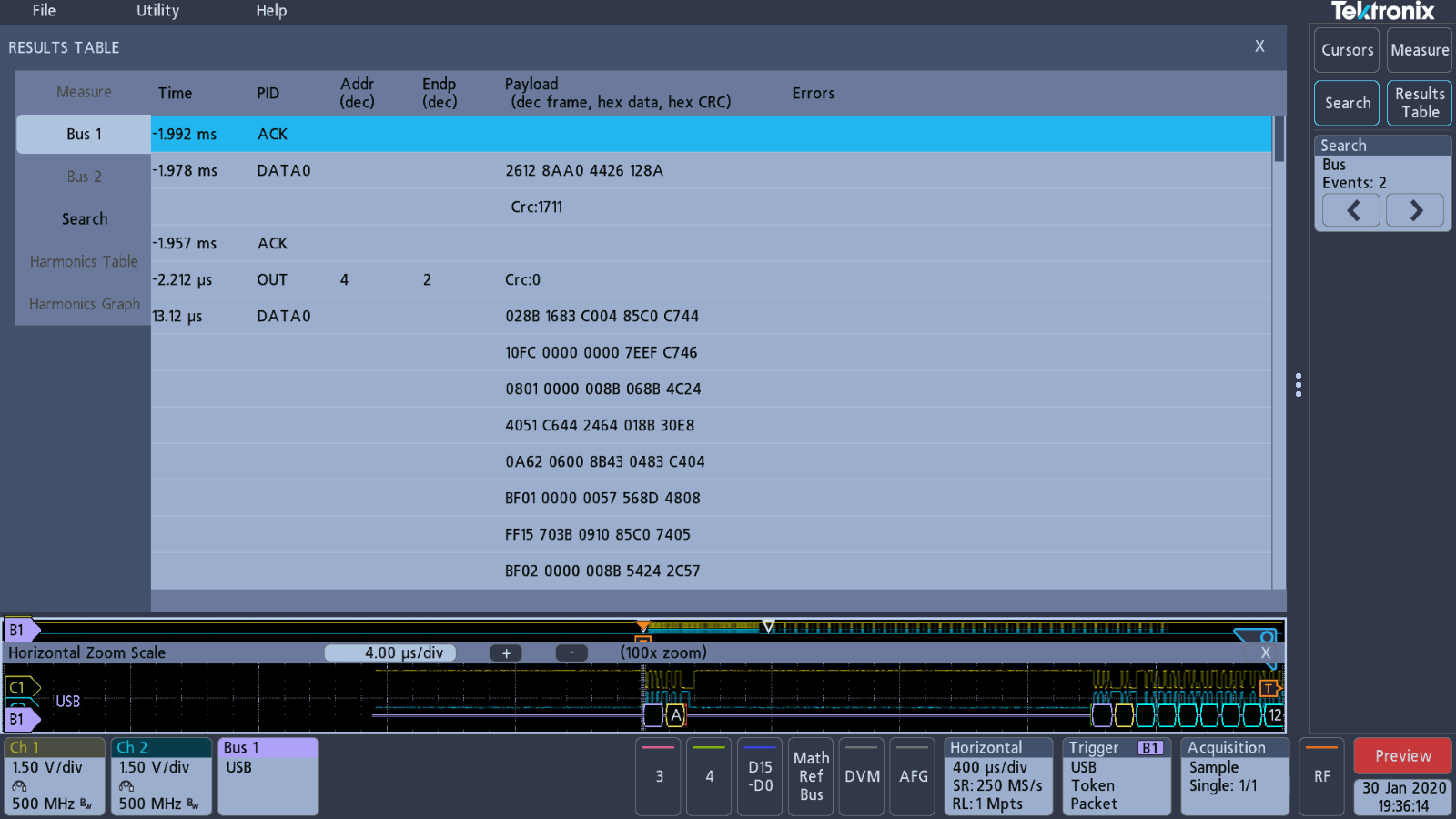
Opening the results table and expanding the view shows the capture of the 'Out' token.
Conclusions
Hopefully this has shown enough information on the serial bus capturing capabilities of the 3 Series MDO. I have a serious lack of knowledge on the majority of these bus signals, so I apologise for any errors or omissions on my behalf. At the moment I haven't got round to capturing the MIPI D-PHY signal, so that is the only one missing from the board.
Yet again the demo board from Tektronix has shown how useful it is to demonstrate the functionality of the oscilloscope and learn about its controls.
Please feel free to ask, if you want to see anything more specific.
Top Comments