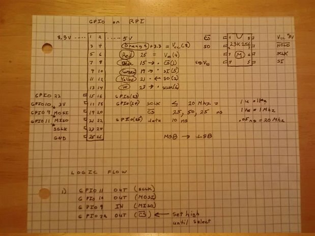
I have learned that I should use pins 24/26 as CE0/CE1 instead of pin15(GPIO 22) because this alleviates me writing extra code. I plan on using Python SPIDEV from GitHub...
I decided to pull everything and remount changing colored wires and new positions and the thing is working! So cannot tell what is wrong!?! I have a few bit flips, but that may be timing or something. But progress is being made. Thanks for the help. Next is a code rewrite/cleanup because so much extra stuff
No scope (Yet), but have voltmeter and was thinking to use over SO/MISO and ground. It is also a current meter as well. Will do some I2C next after this works.
Well I am stuck again, but this time I think software. I can program using python, but nothing gets stored(?) and the chip does not respond (0XFF) ! If I unplug the chip's +3 volts, all responses are 0X00... I am too close to this to figure it out. Ask me questions to send me on the right track.
Congrats!!! It is good to hear everything works fine with the SPI memory. Good luck with the tests!
After you play with SPI maybe you can try some I2C chips as well. There are so many interesting I2C chips (pressure, temp, acceleration sensors, gyros, magnetometers, ...) you can attach to the RPi.
Congrats!!! It is good to hear everything works fine with the SPI memory. Good luck with the tests!
After you play with SPI maybe you can try some I2C chips as well. There are so many interesting I2C chips (pressure, temp, acceleration sensors, gyros, magnetometers, ...) you can attach to the RPi.
I decided to pull everything and remount changing colored wires and new positions and the thing is working! So cannot tell what is wrong!?! I have a few bit flips, but that may be timing or something. But progress is being made. Thanks for the help. Next is a code rewrite/cleanup because so much extra stuff
No scope (Yet), but have voltmeter and was thinking to use over SO/MISO and ground. It is also a current meter as well. Will do some I2C next after this works.
Well I am stuck again, but this time I think software. I can program using python, but nothing gets stored(?) and the chip does not respond (0XFF) ! If I unplug the chip's +3 volts, all responses are 0X00... I am too close to this to figure it out. Ask me questions to send me on the right track.