Here are my notes so far. Any comments or issues please let me know. I think I am on the right track.
Ok!
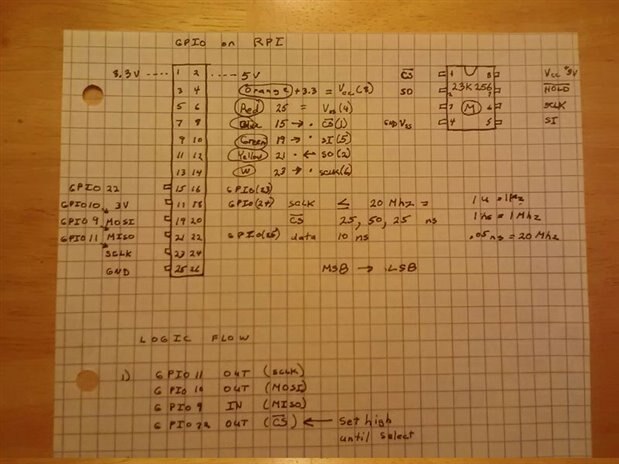
I have learned that I should use pins 24/26 as CE0/CE1 instead of pin15(GPIO 22) because this alleviates me writing extra code. I plan on using Python SPIDEV from GitHub...
Thanks for Elektor Academy - Hardware Hacking the RPi pointing this out. Excellent if you want the details 
Question: What to do with HOLD pin? I need it to stayhHigh. Also how to make the CS pin be high but go low when transmitting?
Thanks,
Clem
Hi Clem,
Use a pull-up resistor (10K should be just fine) with the HOLD pin.
The CS handling is done by the driver.
I found an example here involving MCP3008. This chip uses an active low chip select as well as the 23K256. Good luck!
Sure I will sum this up experiences and all. Thanks @Michael Kellett for kind words of encouragement 
I'm glad it's working - how fast are you running the spi clock and how long are the wires ?
Any chance of a picture ?
MK
Well guess what...
I decided to pull everything and remount changing colored wires and new positions and the thing is working!
So cannot tell what is wrong!?! I have a few bit flips, but that may be timing or something. But progress is being made. Thanks for the help. Next is a code rewrite/cleanup because so much extra stuff
Clem
Well post the code here and I'll see if I can pick my way though it.
If you are bit banging the SPI you can add logging features to the code to trace each pin state as it runs.
MK
HI @bbolo1
No scope (Yet), but have voltmeter and was thinking to use over SO/MISO and ground. It is also a current meter as well. Will do some I2C next after this works.
Thanks,
Clem
HI @bbolo1
No scope (Yet), but have voltmeter and was thinking to use over SO/MISO and ground. It is also a current meter as well. Will do some I2C next after this works.
Thanks,
Clem
Sure I will sum this up experiences and all. Thanks @Michael Kellett for kind words of encouragement 
I'm glad it's working - how fast are you running the spi clock and how long are the wires ?
Any chance of a picture ?
MK
Well guess what...
I decided to pull everything and remount changing colored wires and new positions and the thing is working!
So cannot tell what is wrong!?! I have a few bit flips, but that may be timing or something. But progress is being made. Thanks for the help. Next is a code rewrite/cleanup because so much extra stuff
Clem
Well post the code here and I'll see if I can pick my way though it.
If you are bit banging the SPI you can add logging features to the code to trace each pin state as it runs.
MK