element14 Community
element14 Community
    Register Log In
  • Site
  • Search
  • Log In Register
  • Community Hub
    Community Hub
    • What's New on element14
    • Feedback and Support
    • Benefits of Membership
    • Personal Blogs
    • Members Area
    • Achievement Levels
  • Learn
    Learn
    • Ask an Expert
    • eBooks
    • element14 presents
    • Learning Center
    • Tech Spotlight
    • STEM Academy
    • Webinars, Training and Events
    • Learning Groups
  • Technologies
    Technologies
    • 3D Printing
    • FPGA
    • Industrial Automation
    • Internet of Things
    • Power & Energy
    • Sensors
    • Technology Groups
  • Challenges & Projects
    Challenges & Projects
    • Design Challenges
    • element14 presents Projects
    • Project14
    • Arduino Projects
    • Raspberry Pi Projects
    • Project Groups
  • Products
    Products
    • Arduino
    • Avnet & Tria Boards Community
    • Dev Tools
    • Manufacturers
    • Multicomp Pro
    • Product Groups
    • Raspberry Pi
    • RoadTests & Reviews
  • About Us
  • Store
    Store
    • Visit Your Store
    • Choose another store...
      • Europe
      •  Austria (German)
      •  Belgium (Dutch, French)
      •  Bulgaria (Bulgarian)
      •  Czech Republic (Czech)
      •  Denmark (Danish)
      •  Estonia (Estonian)
      •  Finland (Finnish)
      •  France (French)
      •  Germany (German)
      •  Hungary (Hungarian)
      •  Ireland
      •  Israel
      •  Italy (Italian)
      •  Latvia (Latvian)
      •  
      •  Lithuania (Lithuanian)
      •  Netherlands (Dutch)
      •  Norway (Norwegian)
      •  Poland (Polish)
      •  Portugal (Portuguese)
      •  Romania (Romanian)
      •  Russia (Russian)
      •  Slovakia (Slovak)
      •  Slovenia (Slovenian)
      •  Spain (Spanish)
      •  Sweden (Swedish)
      •  Switzerland(German, French)
      •  Turkey (Turkish)
      •  United Kingdom
      • Asia Pacific
      •  Australia
      •  China
      •  Hong Kong
      •  India
      •  Korea (Korean)
      •  Malaysia
      •  New Zealand
      •  Philippines
      •  Singapore
      •  Taiwan
      •  Thailand (Thai)
      • Americas
      •  Brazil (Portuguese)
      •  Canada
      •  Mexico (Spanish)
      •  United States
      Can't find the country/region you're looking for? Visit our export site or find a local distributor.
  • Translate
  • Profile
  • Settings
RoadTests & Reviews
  • Products
  • More
RoadTests & Reviews
RoadTest Forum Discussion: How Would You Roadtest the MagAlpha Angle Sensor Kit
  • Blogs
  • RoadTest Forum
  • Documents
  • RoadTests
  • Reviews
  • Polls
  • Files
  • Members
  • Mentions
  • Sub-Groups
  • Tags
  • More
  • Cancel
  • New
Join RoadTests & Reviews to participate - click to join for free!
Actions
  • Share
  • More
  • Cancel
Forum Thread Details
  • Replies 26 replies
  • Subscribers 2562 subscribers
  • Views 5311 views
  • Users 0 members are here
  • MPS MA732 MagAlpha Angle Sensor Kit with Servo Motor
Related

Discussion: How Would You Roadtest the MagAlpha Angle Sensor Kit

rscasny
rscasny over 3 years ago

imageI usually provide the technical details and documentation on a roadtest page for people to look over at their leisure.

This material usually gives people ideas on how they would like to roadtest a product. But I think sometimes, it's good to actually talk about how one would roadtest a product, due to perhaps it's something new for many people, or it needs a little more background.

I think this angle sensor kit is one of those products.

When we decided to roadtest this kit, we initially provide the sensor and the communications board. But with only those things, the roadtester would have to mount the magnet and the sensor to the motor shaft. Seemed like heavy lifting, so the supplier came back with the kit that's on this page (right):

community.element14.com/.../mps_magnetic_angle_p

The sensor board is mounted to the end of the motor shaft already (as well as the magnet). The roadtester would need to hook it all up, connecto the Arduino board (not shown in the image at the right) and spin the motor.

But still, how do you actually test it.

More importantly, why is this sensor important to roadtest?

This clip from the sponsor's website pretty much explains it:

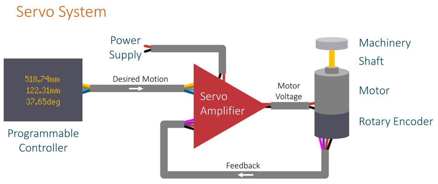
The ability to detect position or speed is a fundamental requirement in the control and monitoring of many mechanical systems. Slow speed position measurement in applications such as motorized actuators has historically used resistive potentiometers. In high-speed applications such as servo motors, optical encoders have typically been used. Though potentiometers are inexpensive, they suffer from the drawback of being a moving contact-based assembly, which brings the associated issues of mechanical contact wear and susceptibility to damage from external environmental factors including moisture and dirt ingress. Optical encoders offer high accuracy, but come at a higher price due to the complex nature of their construction. Engineers can solve this dilemma by using contactless rotary magnetic angle sensors that implement Hall-effect sensing.

This page goes into detail about the angle sensor, specifically about its SpinAxis technique: www.monolithicpower.com/.../introduction-to-the-magalpha-magnetic-angle-sensor-family

The kit we are providing to the roadtester is a motor control kit. But we would like to get roadtesters to take a closer look at the angle sensor. Run some tests, play with it, and give some feedback or thoughts about it.

So, that's my backgrounder.

What do you think?

How would you test the sensor?

Even if you don't have the time to take on this roadtest, I'd appreciate your input. It would benefit those members who are thinking about applying.

Thanks.

Randall Scasny
RoadTest Program Manager

  • Sign in to reply
  • Cancel

Top Replies

  • shabaz
    shabaz over 3 years ago +6
    Hi Randall, That sensor has incredibly high granularity for position sensing, and works to a very good speed (60,000 RPM) and so the uses for it could span across a lot of things that traditionally would…
  • shabaz
    shabaz over 3 years ago +4
    Having read a bit more on it, the sensor is very interesting and designed for new and existing applications. The sensor can be read digitally (SPI interface), or it offers a normal rotary encoder output…
  • robogary
    robogary over 3 years ago in reply to ajmorin369 +4
    Hi A.J. - I can't speak officially for the Road Test selection committee, and I dont know what and how many Road tests you've applied for, but I can share my experience. When I first got going with Road…
Parents
  • shabaz
    shabaz over 3 years ago


    Having read a bit more on it, the sensor is very interesting and designed for new and existing applications. The sensor can be read digitally (SPI interface), or it offers a normal rotary encoder output, for (say) retrofitting where an optical encoder would go, or for places where an optical encoder is more impractical (e.g. greasy/dirty machine environments), as well as a PWM output.
    I think this RoadTest lends itself really well for project/application-based testing, i.e. building and working with it and seeing if it suits particular applications or not.

    I think it would be interesting for those who like working with FPGAs or microcontrollers, to create all sorts of software/HDL applications for it. This reminds me of the Measurement HAT RoadTest, where Jan and I had quite a lot of fun discovering how to use the device and creating apps.

    It doesn't need a lot of FPGA or microcontroller experience to get going with the sensor, since there are many resources for connecting existing encoders to FPGAs/processors, (e.g. plenty of online tutorials on encoders with Arduino) but of course if the user has experience with that then it helps.

    For those that do not like working with FPGAs or microcontrollers, there is the possibility to try to retrofit wherever a rotary encoder is currently used, or alternatively to explore using the PWM output.

    For the example applications I could think of (some are listed below), not all require the servo motor, but the motor is already a ready-made example application, excellent for seeing the sensor in operation (the sensor acts as the feedback to manage the motor position and speed basically).

    The diagram here shows how servos work, however the 'Rotary Encoder' in the diagram is actually the magnetic sensor, and the 'Servo Amplifier' is actually a brushless DC driver.  The Programmable Controller in the diagram could be replaced by a PC connected via USB. This is a very simplified diagram, modern servo systems are a lot more advanced.

    image

    Some example applications:

    (1) Servo motor testing
    With the supplied kit, you could use it to see how much torque you can apply to a servo motor, before its position is affected, and you could see how quickly the servo motor recovers back to its original position if you knock it, by seeing how quickly the PWM recovers, or by recording the rotary encoder value repeatedly (e.g. using a microcontroller and storage) and then plotting the values. This is all great for CNC and robotics applications. The supplied servo is already effectively one axis for (say) a robot arm, and the sensor is already within the control loop, but there's nothing stopping a user from attaching the encoder output in parallel to their own microcontroller, e.g. Arduino or whatever one is comfortable with.

    (2) Position sensing digital read-outs (DRO) for milling or lathe machines
    These are environments that are not nice for optical encoders, and direct linear measurement is expensive if done properly. It could be possible to build a far cheaper DRO connected to the dial on such machines, i.e. an indirect measurement. It beats having to manually count the rotation angle and number of turns. For this, the sensor board would be extracted from the end of the servo motor.

    (3) Distance measurement
    I think a really granular (sub-millimeter) measurement wheel is possible, again by extracting the board from the servo motor.

    (4) Practicality of using magnetic sensors investigation
    From the sounds of it, it could greatly reduce costs to use a magnetic sensor, since there's no need for any fancy coupling that would be required for an optical encoder shaft. However, I don't know if this is the case, so it would be interesting if someone tried it - i.e. attach a magnet to a shaft themselves, and see how accurately the magnetic sensor needs to be positioned and if the results change significantly if there is misalignment. This would be really useful info, including magnet recommendations.

    • Cancel
    • Vote Up +4 Vote Down
    • Sign in to reply
    • Cancel
Reply
  • shabaz
    shabaz over 3 years ago


    Having read a bit more on it, the sensor is very interesting and designed for new and existing applications. The sensor can be read digitally (SPI interface), or it offers a normal rotary encoder output, for (say) retrofitting where an optical encoder would go, or for places where an optical encoder is more impractical (e.g. greasy/dirty machine environments), as well as a PWM output.
    I think this RoadTest lends itself really well for project/application-based testing, i.e. building and working with it and seeing if it suits particular applications or not.

    I think it would be interesting for those who like working with FPGAs or microcontrollers, to create all sorts of software/HDL applications for it. This reminds me of the Measurement HAT RoadTest, where Jan and I had quite a lot of fun discovering how to use the device and creating apps.

    It doesn't need a lot of FPGA or microcontroller experience to get going with the sensor, since there are many resources for connecting existing encoders to FPGAs/processors, (e.g. plenty of online tutorials on encoders with Arduino) but of course if the user has experience with that then it helps.

    For those that do not like working with FPGAs or microcontrollers, there is the possibility to try to retrofit wherever a rotary encoder is currently used, or alternatively to explore using the PWM output.

    For the example applications I could think of (some are listed below), not all require the servo motor, but the motor is already a ready-made example application, excellent for seeing the sensor in operation (the sensor acts as the feedback to manage the motor position and speed basically).

    The diagram here shows how servos work, however the 'Rotary Encoder' in the diagram is actually the magnetic sensor, and the 'Servo Amplifier' is actually a brushless DC driver.  The Programmable Controller in the diagram could be replaced by a PC connected via USB. This is a very simplified diagram, modern servo systems are a lot more advanced.

    image

    Some example applications:

    (1) Servo motor testing
    With the supplied kit, you could use it to see how much torque you can apply to a servo motor, before its position is affected, and you could see how quickly the servo motor recovers back to its original position if you knock it, by seeing how quickly the PWM recovers, or by recording the rotary encoder value repeatedly (e.g. using a microcontroller and storage) and then plotting the values. This is all great for CNC and robotics applications. The supplied servo is already effectively one axis for (say) a robot arm, and the sensor is already within the control loop, but there's nothing stopping a user from attaching the encoder output in parallel to their own microcontroller, e.g. Arduino or whatever one is comfortable with.

    (2) Position sensing digital read-outs (DRO) for milling or lathe machines
    These are environments that are not nice for optical encoders, and direct linear measurement is expensive if done properly. It could be possible to build a far cheaper DRO connected to the dial on such machines, i.e. an indirect measurement. It beats having to manually count the rotation angle and number of turns. For this, the sensor board would be extracted from the end of the servo motor.

    (3) Distance measurement
    I think a really granular (sub-millimeter) measurement wheel is possible, again by extracting the board from the servo motor.

    (4) Practicality of using magnetic sensors investigation
    From the sounds of it, it could greatly reduce costs to use a magnetic sensor, since there's no need for any fancy coupling that would be required for an optical encoder shaft. However, I don't know if this is the case, so it would be interesting if someone tried it - i.e. attach a magnet to a shaft themselves, and see how accurately the magnetic sensor needs to be positioned and if the results change significantly if there is misalignment. This would be really useful info, including magnet recommendations.

    • Cancel
    • Vote Up +4 Vote Down
    • Sign in to reply
    • Cancel
Children
No Data
element14 Community

element14 is the first online community specifically for engineers. Connect with your peers and get expert answers to your questions.

  • Members
  • Learn
  • Technologies
  • Challenges & Projects
  • Products
  • Store
  • About Us
  • Feedback & Support
  • FAQs
  • Terms of Use
  • Privacy Policy
  • Legal and Copyright Notices
  • Sitemap
  • Cookies

An Avnet Company © 2025 Premier Farnell Limited. All Rights Reserved.

Premier Farnell Ltd, registered in England and Wales (no 00876412), registered office: Farnell House, Forge Lane, Leeds LS12 2NE.

ICP 备案号 10220084.

Follow element14

  • X
  • Facebook
  • linkedin
  • YouTube