RoadTest: Nordic Bluetooth LE Audio Development Kit nRF5340 DK
Author: Gough Lui
Creation date:
Evaluation Type: Evaluation Boards
Did you receive all parts the manufacturer stated would be included in the package?: True
What other parts do you consider comparable to this product?: PacketCraft nRF52840 and Laird Connectivity BL5340, the Telink TLSR9/B91 evaluation kit and NXP NXH3675 solution.
What were the biggest problems encountered?: Board design is a bit cramped, additional kits necessary to fully evaluate all functionality, mono onboard codec, first-time user of Visual Studio Code and nRF Connect add-in resulted in some initial build and flash problems.
Detailed Review:
Nordic Semiconductor nRF5340 Bluetooth Low-Energy Audio Development Kit RoadTest Review
by Gough Lui (December 2022 – February 2023)
Happy New Year to all! It’s been a little while since I last delivered a RoadTest review, but I am back on the road at long last. This review was awarded last year and due to the awkward timing across the holidays, has taken me a bit longer than anticipated to deliver. However, as usual, I hope you enjoy it and find it interesting, useful, informative or entertaining.
I’ve been a bit of an audiophile myself – not quite a crazy one that will pay for snake oil, but I do appreciate a good set of headphones, a decent DAC and uncompressed FLACs when I can. While at home, I generally stay with wired connections for the better quality. While on the road, the convenience of wireless Bluetooth audio often trumps the slight degradation in sound quality.
Bluetooth audio is predominantly via Bluetooth Classic PHY and A2DP profiles with SBC being the lowest-common-denominator. However, on my visit to ElectroneX 2022, I was told by a Nordic Semiconductor representative all about the new LC3 codec in Bluetooth LE Audio and that the new nRF5340 Audio DK would be imminently available. Since then, I’ve been interested in what LC3-encoded audio sounds like and whether LE Audio could match the range offered by classic A2DP while delivering power efficiency benefits.
Thanks to element14 and Nordic Semiconductor for selecting me as one of the lucky members to participate in this RoadTest. If you have any questions, please leave a comment and I will answer as best as I can – otherwise, I would appreciate a like or share this review with someone who might be interested.
Bluetooth has been with us for quite a while, but has continued to evolve with newer versions containing new physical layer (PHY) modulations and codings, optional audio codecs and device profiles being released. However, from a consumer standpoint, usually users don’t think much about this and just expect Bluetooth to just work. It might surprise many readers to know that their Bluetooth stereo A2DP headphones are most likely running on the Bluetooth Classic PHY layer using low-complexity sub-band codec (SBC) as the “lowest-common-denominator”. While this mostly “just works”, it’s perhaps not ideal from an audio quality and power efficiency perspective now that better codecs and PHYs exist. It also adheres to the traditional one-to-one connectivity architecture which makes certain use cases difficult (e.g. two headsets listening into one program from one host). Higher quality, while possible through optional codecs such as aptX, AAC, LDAC and LHDC, but both sides need to support it for it to work and that’s not always trivial. With the advent of true-wireless stereo (TWS) earbuds which have smaller sizes, lower power consumption and more efficient data transmission has become a big priority.
As a result, the Bluetooth SIG has introduced in 2020 (and continued to revise) the Bluetooth Low-Energy Audio (LE Audio) specification which combines the LE PHY with a new codec known as LC3 (short for Low Complexity Communications Codec) developed by Fraunhofer and Ericsson. While the latest LE PHY supports 2Mbit/s connectivity as well as low-rate long-range coded connectivity often used in mesh connectivity which may seem similar to Bluetooth Classic, lowering the bitrate with LC3 encoding is said to provide battery life, range and air-time benefits while improving audio quality and resilience to interference and remaining computationally efficient. Bitrates used can scale from 24kbit/s through to 124kbit/s with 32kbit/s (16kHz, 10ms frames) and 48kbit/s (24kHz, 10ms frames) being mandatory for Basic Audio Profile v1.0 compliance. For reliability, low-latency transmissions retransmit their data from 2, 4 or 5 times depending on the bitrate while high-reliability transmissions use 4 or 13 retransmissions at the cost of increased latency. The LE audio standard breaks each channel into its own stream, enabling native TWS systems that don’t need to have a primary-to-secondary link and also builds up new broadcast audio features named “Auracast” with applications for public sound with a key application being for hearing aids. Such a system also synchronises receivers based on a presentation time as well, ensuring broadcasted audio is received in synchrony.
Being still a new standard that is suffering a bit from a “chicken-and-egg” situation, there’s very few consumer products on the market at this time that natively implements LE Audio. It is supported on Android 13 and later, however, it seems Apple iOS isn’t quite ready for it yet and products that support it are only just appearing on the market and often in a dual-mode way so as not to leave users stranded without audio.
Nordic Semiconductor’s nRF5340 Audio DK is a product that allows for evaluating the performance of LE Audio on one of Nordic’s most modern SoCs using a purpose-designed evaluation board and software bundle. As it turns out, this kit uses code licensed from PacketCraft for the LE Audio side and T2 Software for the LC3 codec. Other evaluation alternatives include systems based on the nRF52840 and Laird Connectivity BL5340 by PacketCraft (perhaps predating Nordic’s solution and slightly more comprehensive), the Telink TLSR9/B91 evaluation kit (which is rather inexpensive, perhaps less well-known) and the NXP NXH3675 solution (which appears to be limited in availability).
I have seen some other vendors claim their SoCs are ready or suited for LE Audio applications, and that might be true from a computational resource standpoint, but implementation, coding and licensing is entirely left to the end user. That makes it much less attractive compared to Nordic’s proposition of a “turn-key” evaluation with libraries that are licensed for use with their SoCs.
That being said, as LE Audio matures, SoCs and ASICs that support LE Audio will also become an option and evolve further. The Qualcomm QCC5171 is a dual-mode option, along with the Airoha AB1565, AB1568 and AB1585-series SoCs. The latter, especially, appear to be loosely based around ARM-based microcontrollers combined with software, DSPs and DAC/ADCs to form a complete solution in the one chip. I have not, however, seen evaluation kits for these parts yet.
To evaluate LE Audio using the Nordic nRF5340 Audio DK requires at least two kits, one to act as the gateway (source) and the other to act as the handset (sink) device. However, as the devices are designed such that they are mono only, to evaluate stereo requires two sink devices, one for left and one for right, bringing the total devices up to three. Alternatively, an external stereo codec can be used, although some software modifications seem necessary. In the case of evaluating Auracast (broadcast) audio, while two devices can be used, you really don’t see the difference without additional receivers and transmitters to simulate a multi-receiver and/or multi-gateway set-up. As a result, the equipment required could add up as each board currently is listed on element14 AU for AU$289.20 including GST at the time of publication.
While I did initially write a proposal encompassing two or three kits, I ultimately received two kits for this evaluation. This is a good thing, as I have no other LE Audio capable devices at this time.
The Nordic Semiconductor nRF5340 Audio Development Kits arrived packed in a thin natural cardboard-coloured box with multi-colour print. I suppose this is environmentally friendly, although the left one did get a little crushed in transit.
Inside, a quick-start leaflet is provided, with the board itself packaged in a static shielding bag and a battery in a thin foam padding.
The two boards I received seemed to differ quite a bit by serial number – one being manufactured in Week 13 of 2022 and the other on Week 20 of 2022. Nevertheless, both units are identical barring subtle differences in PCB substrate colour (one is a brown and the other is more of a fibreglass green).
The design is quite striking, with a central cut-out for the Nordic logo. It’s also relatively packed with many connectors, test pads, LEDs and solder jumpers.
One of the boards had a bent pin in transit – nothing difficult to straighten out. A nice touch is that the bottom of the PCB is protected by a plastic shield cover which avoids issues when placing the board onto conductive surfaces (e.g. ESD mats) or potentially touching stray wire scraps. This side of the board exposes a microSD card slot, a programming header and NFC antenna connector.
The opposite side of the board is home to the slide power switch which can be a little finnicky to operate and the battery connector.
Along one of the short sides is two 3.5mm stereo jacks, although the board is mono and only uses the left-side contacts. One serves as a headphone out and the other as a line-in.
Finally, a USB-C connection provides both power for the board to operate and charge, as well as data for the USB Audio, programming and debug capability.
A view from underneath shows that the PCB is pretty packed from the underside too. I’ll take a closer look at what’s on the PCB in the next sub-section.
The kit is supplied with a LP803450 protected lithium-polymer battery, rated at 3.7V 1500mAh. This allows the kit to be operated without connection to USB for power.
The cell is terminated in a small three-pin plug including a thermistor connection.
As the board is quite dense, I decided to take some close-up photos to show the board’s components in more detail.
Starting from the top – in the top left is the PCB-mounted ceramic chip antenna and its matching network. The J1 SWF connector allows for attachment of external antenna or test equipment, being switched it will disconnect the onboard antenna. In the white square below is the nRF5340 that is running the show. The two 3.5mm jacks can be seen in the middle, with a header P14 that allows for accessing the signals on those jacks more conveniently. The onboard PDM microphone is on the server side, but a hole is made in the PCB for the sound to travel through. Header P15 allows for a second PDM source to be connected, while header P5 offers the ability to debug the onboard codec interface. The onboard codec, a Cirrus Logic CS47L63, is located in the top right of the image as U2. Unfortunately, this is a mono codec, leading to a single channel only.
The centre of the board is mostly a “hole” for the Nordic logo, but there is the P10 header for an external hardware codec – perhaps if you would like to provide your own stereo one. The P13 header is used for debug connections to the nRF5340. The outside pin sockets are Arduino Uno-compatible layout for use with shields.
The bottom of the top side contains a switch that allows for toggling power to the debug circuitry. This switch is covered by tape but is very small and tricky to actuate. There is an array of push buttons for controlling the device and a line of LEDs for various status indications. A set of solder jumpers and three-pin headers allow current measurement for the nRF core, hardware codec supplies and battery. The P11 header is used for auxiliary interfaces with the onboard hardware codec. In the centre of the board resides the nPM1100 power management IC which provides the rails and handles the battery, labelled U3 and surrounded by its supporting components.
On the underside, we can see some of the complexity that this board entails. The USB interface first comes through a MaxLinear (formerly Exar) XR22414 USB 2.0 Hub chip, as there are multiple peripherals onboard. Peripherals include the FTDI FT2232H which is providing an SPI interface to the second nRF5340 serving as the debug interface. There is a pair of SN74AXC4T774RSVR bus transceivers interfacing with the microSD card and the FTDI interface for level shifting, an array of INA231 current sense amplifiers for onboard power monitoring and a number of FSA2466UMX analog switches to perform signal routing.
The PDM microphone is visible as U5. Aside from the switches, there is also SLG59M1512V MOSFET power switches and a M74VHC1GT14DFT2G op-amp to provide supply switching to the codec.
While it is quite packed, it is notable that while J4 provides a connection for a flexible NFC antenna, none is included in this kit. Furthermore, there is also no front end module built-in even though the software does support the use of a nRF21540 to boost output power up to +20dBm. It seems such a module is better used with a full-size development board instead, but would add a sizeable boost to broadcast audio range (by bringing transmission power from Class 2 to Class 1 levels).
This section predominantly considers the initial ground-work necessary to get the kit to a safe, operational status and the support provided by the manufacturer. I will be coming to this as a complete novice at working with Nordic Semiconductor’s toolchains and with Microsoft Visual Studio Code, as would become evident in some of the minor hiccups along the way.
Documentation for the Nordic Semiconductor nRF5340 Audio Development Kit consists of their product information page, a product brief PDF, PCB design/schematic ZIP file, Infocenter and SDK article. The latter three are probably the most useful of all of them as I found myself referring to the schematic to understand the design of the board and the Infocenter/SDK article to understand how to build the software. While the SDK article may seem a bit brief at first, it’s very dense with useful information. I found the documentation overall to be quite good, although some of the build flags did not seem to be completely documented as to which ones should or should not be used, whether there are any issues with using several of them together and what some of the more obscure ones do. I suppose one can always examine the code to learn more.
While I did not need to use any form of support, I that the official channel of support is the Nordic DevZone forums which leverages both community members and employees of Nordic Semiconductor.
Installing the software is a bit of a game of software whack-a-mole. A strong internet connection is recommended, as downloading extra software becomes necessary as things go along.

The first step is to install nRF Connect for Desktop, which works as the main control-center for all of Nordic Semiconductor’s tools.
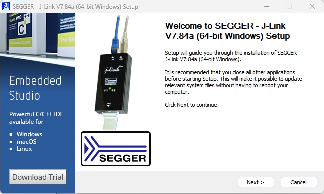

During installation, it seems to also install Segger J-Link which is required for communication with target devices.


From there, the Toolchain Manager has to be installed, then the latest version of the SDK which the manager downloads directly. Default installation goes to C:\ncs. It is at this time that the user should also install Microsoft Visual Studio Code.
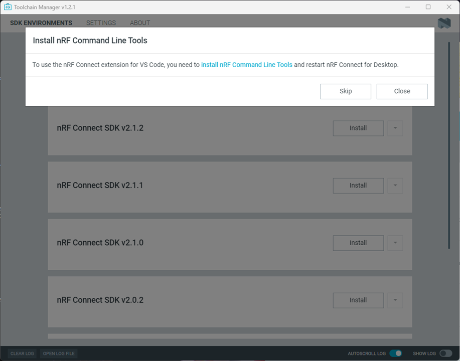
Things are not ready yet, as in order for this to work, yet another tool is required. The nRF Command Line Tools needs to be downloaded and installed.
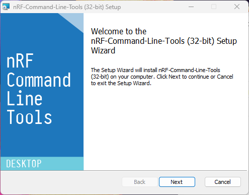
Once that is done, further extensions for Visual Studio Code need to be downloaded and installed, along with recommended extensions from Microsoft.

Only now are we prepared to begin developing.

Being completely new to Visual Studio Code, I became confused very quickly after installation. Having set it up, I opened the example project but I seemed to get nowhere fast. I tried to build using buildprog.py after installing Python and supporting libraries as required, but alas, it was not quite working.

I installed dependencies, fussed about a bit, tried various ways to build but realised tools such as west were not in the path.

I then decided to open a command line from the nRF Connect for Desktop. This allowed me to build the project at last by Python, but loading was still a problem despite fixing up code protection on the boards using a full erase. It seems that the tool was not detecting the presence of the board.


I managed, in the end, by using the manual command line method indicating no issue with the board connection, but there must be an easier way!

It turns out, I was being a complete idiot without knowing it - when using the nRF Connect extension from the left sidebar, it will look like this and everything is there in one place.
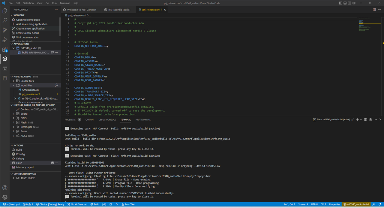
In the one window, it is possible to edit sources, run Kconfig to configure build options graphically, build, load, connect a terminal to the device and debug the build. This is what I would have expected from an IDE.
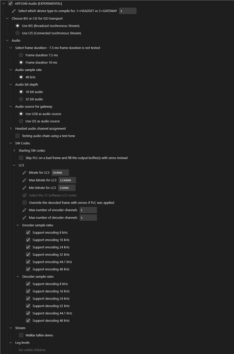
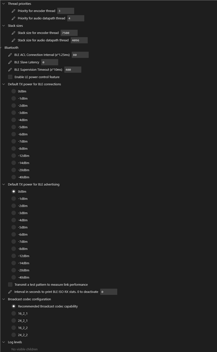
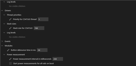
The Kconfig tool is an absolute treat, with pages of options (some untested) for users to tweak. By saving the settings from this, then the firmware can be rebuilt by clicking on the “circular arrow” icon next to Build for a pristine build. This allows easily changing headset/gateway roles, BIS/CIS mode, walkie-talkie demo, power monitoring and more. Unfortunately, it doesn’t seem all options work equally well or are comprehensively documented, but it is still very much appreciated.
From there, loading the firmware to the boards is as easy as clicking Flash. Once the firmware is correctly loaded on the boards, they will change from the yellow colour (as shipped) to either green (gateway), blue (headset-left) or magenta (headset-right). Such an arrangement ensures the user always has the latest firmware build for their boards, but doesn’t allow an “out-of-the-box” immediate evaluation.
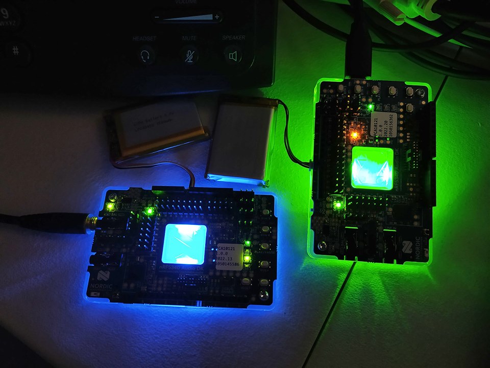
While this works quite well, one annoyance I find is that the firmware seems to love LED lights. I generally don’t like having LEDs shining in my room at night, or chewing needless battery. As a result, one of the first modifications I made was to replace every led_on and led_blink function call with the equivalent led_off call. This takes out most of the LEDs but not all – the CODEC one appears to need a hardware cut to a trace while the RGB2 is controlled by the BLE stack requiring a bit more investigation, and OB/EXT also seems to be elusive as well. A simple build option to disable LEDs would definitely be helpful.
Speaking of modification of sources – I also noticed that in my dabbling, I’ve occasionally made changes to the code which I later regretted. In a panic, I searched the internet for the file in particular, coming up empty handed. I ultimately reinstalled the toolchain, before I later realised that the code was available in the nrfconnect/sdk-nrf GitHub repository. Perhaps if this was more obvious, rather than hidden away behind automated Toolchain Manager processes, then I would have saved some panic and download quota. However, I do admit, this is a bit of a mea culpa as far as things are concerned and may just reflect my unfamiliarity with how Nordic’s development sources are set up.
At the moment, the microSD slot doesn’t seem to be used much except for logging and no NFC pairing capability appears to be demonstrated at this time. Extending this to be able to play or record music to card or to pair via “tapping” a device could prove valuable.
In terms of hardware set-up, there is not much to do. Connect the battery to the connector, find a USB-C cable to attach it to the computer, plug it in and turn it on. Because of a design quirk, the battery can only charge when the unit is turned on, which I feel is a little unfortunate, as it also means the other circuitry is consuming power and perhaps slowing the charge down a bit.
When plugged into a PC, the board may take some time to be properly detected and set-up. I found that the serial drivers seemed to be downloaded from Windows Update and didn’t work immediately. After a few minutes though, it resolved by itself.


When configured as a gateway, by default, it acts as a USB audio device allowing you to play and record audio as if it were an attached sound-card.


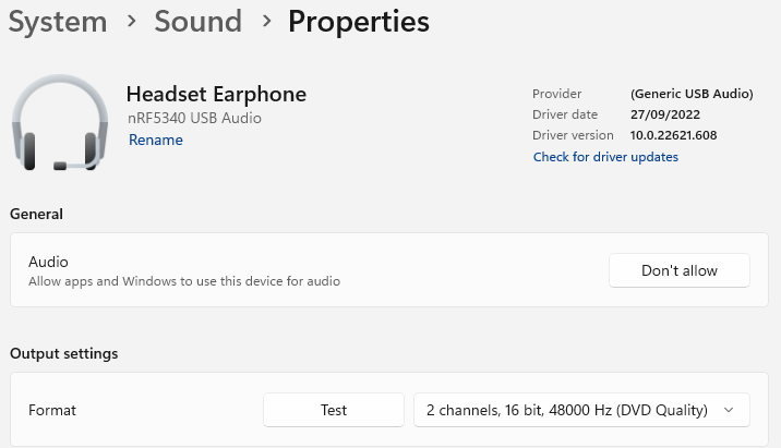
The device supports 48kHz 16-bit Stereo audio by default.
While the solution was functional, I was not satisfied with having a battery flailing about which could damage its wires and connector, nor with the number of exposed header pins which could be ESD magnets or present a sharps hazard. As a result, I designed a two-part 3D printed casing to work with the existing base-plate.
The bottom contains a well in which the battery is mounted using double-sided mounting tape. The wires can lead out of a channel in the side while the development kit slides in from the side.
This configuration keeps the battery safe and attached to the base like a back-pack but doesn’t solve the problem of the pins.
A lid was fashioned that would just cover over the top of the unit to protect the pins while still allowing access to the connectors on the side.
It’s chunky, it’s square, but it’s good for the job and keeps the rather precious boards safe and sound. It also allows access to the buttons to control playback and volume. It took several attempts to get this right, but you can download the STL files here if you’d like to print your own. nRF5340ADK-Case-by-Gough-Lui.zip
Now that I have the boards operating and safely enclosed, it is time to run some practical tests with the boards.
Before I begin, I will acknowledge that assessments of audio quality are definitely subjective and people may have different thresholds of acceptability in terms of audio impairments. Similarly, depending on your listening environment, equipment and ears, you may be able to hear things that other people will not. I have previously participated in codec comparison tests and consider myself sensitive to codec-induced changes. I use a Asus Xonar Essence STX and AudioTechnica ATH-M50x for my day-to-day listening, preferring a clean and clinical sound signature without breaking the bank. To evaluate the quality and range of the solution, I’ve evaluated the LC3 codec performance on both royalty-based high-definition FLAC files (privately) and with royalty-free compressed sources of music (which is perhaps not that meaningful, but can be published), all while taking a walk around the house (approximately 15m radius, through walls).
Licensed FLAC High-Resolution Music & Other Usage
I tested the quality of LC3 using the kit as if a set of mono Bluetooth headphones by bridging the tip and ring connections with a jumper shunt. Overall, I found the performance of LC3 to be broadly transparent for average listening scenarios and superior to SBC. While SBC often has slightly harsh trebles, LC3 doesn’t seem to have such obvious artifacts, however seems to create slightly less definition in the treble, feeling slightly “rounded”. There also seemed to be a loss of the deepest sub-bass, but I’m not sure if this is the codec’s fault or whether it is due to the DAC (codec) used on the design and its compatibility with the headphones used (ATH-M50x). The packet loss concealment was very similar to that used in voice and videoconferencing, resulting in occasional wavering tones and time dilation effects, but seemed preferable to Bluetooth Classic. Range, as tested, was very similar to Bluetooth Classic based solutions although the digital cliff is steeper as the link tended to fail rapidly once degradation became noticeable.
The best comparison would be with a high-resolution FLAC file played through the chain. While I cannot provide the music samples themselves, I can at least plot the spectrograms to illustrate any differences. To be fair, both the original song and the recorded audio are normalised to -18dBFS before creation of the spectrogram which contains just the first minute of the song for better clarity.
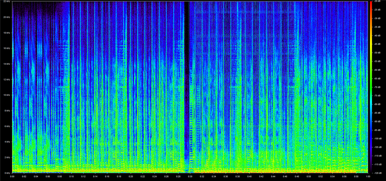
Original digital audio normalised to -18dBFS.
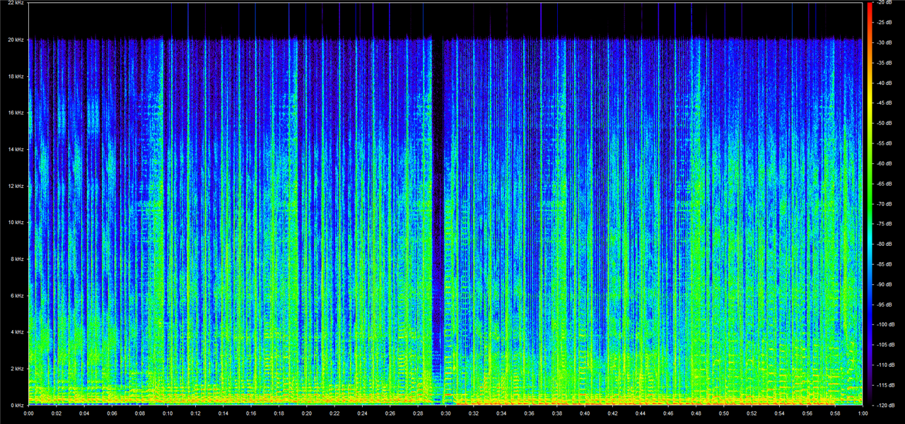
Recorded analog audio after LC3 encoding, transmission, decoding and playback normalised to -18dBFS.
The effects of LC3 coding and the analog chain combined shows a “brick-wall” filter at 20kHz and some slight loss of treble definition. Otherwise, the spectrogram implies a very similar sound with a few treble “spikes” as the audio may have clipped somewhere in the chain. There does seem to be a bit more noise in some of the spectrally quiet regions as well, but this noise energy is likely to be masked by other louder sounds and is a result of psychoacoustic optimisations.
Royalty-Free Compressed 320kbit/s MP3 Audio
In order to provide a more “public” comparison, I’ve decided to take a sampling of tracks from the YouTube Audio Library and cut them together into a (roughly) 4-minute mix to represent various genres of music. The songs used were:
This mix was compiled as 48000Hz 16-bit Mono without any amplitude changes, and played out at maximum volume (0dBFS). A copy was normalised to -18dBFS average as the “original” comparison at 24-bits. Audio played out from the receiver was recorded by a Zoom H4n Handy Recorder at 48kHz 24-bit, the left channel was taken and was volume normalised to -18dBFS to provide a fair comparison (as volume is known to influence preferences). Tests were performed under good signal (same room) and weak signal (~15m range through walls) conditions with and without packet-loss concealment enabled. As these tracks are licensed for use in YouTube videos only, I’ve compiled the comparison as a YouTube video below:
You don't have permission to edit metadata of this video.
Direct Link: https://www.youtube.com/watch?v=UDXGmABX7hs
As the source music was provided as 320kbit/s MP3 and may have already been compressed prior to supply to YouTube, it lacks treble content above 20kHz (sometimes even less). This makes the hard “brick-wall” filter behaviour of LC3 hard to identify, although the majority of people are unlikely to hear frequenices this high. The audio sounds pretty close to the original, perhaps with the slightest hint of a loss of treble definition but is not objectionable at all. It seems to show good compatibility with compressed sources in this instance. Under weak signal circumstances, the packet loss concealment (PLC) would likely do a good job for voice due to the short 7.5ms/10ms frame lengths, although in music it is sometimes more audible as a “unsteady” note or slight time dilation effect, with severe losses resulting in audible interruptions. This behaviour is preferable to being left with gaps or noticeable smears in the audio, as much of the Bluetooth Classic headsets seem to do. The behaviour without PLC shows obvious gaps in the audio, however, the digital cliff is very steep. I had trouble finding a location with “flaky” reception that wouldn’t result in the connection being dropped entirely – the distance was around 1m from this audible degradation to complete loss of program. This is likely to result in a relatively good user experience as it will “just work” until it doesn’t, without much of a middle-ground. However, it doesn’t give much in the way of forewarning of a loss of connection, whereas Bluetooth Classic audio doesn’t seem to be as steep.
In my informal use, I was surprised to find that the latency was almost imperceptible. While watching videos and movies, I am accustomed to having to set a negative audio delay to compensate for Bluetooth audio delays, but in the case of using this Audio DK, I did not have to do so. It was close-enough that I was not too bothered.
Proof of the latency of the system was had by configuring the CONFIG_AUDIO_SOURCE_I2S flag to take audio from the line-in jack. The signal generator of a Rohde & Schwarz MXO4 Oscilloscope was used to provide a gated “beep” into the line-in which was measured on one channel and the delay to receiving the output from the headphone out of the corresponding board was measured using a second channel.

When configured in CIS mode, the latency was measured at 31.8ms.
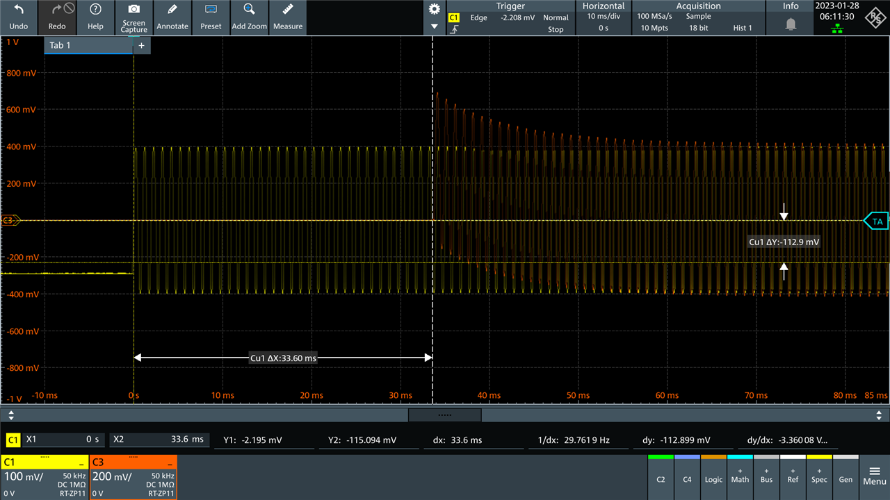
In BIS Auracast mode, the latency was measured at 33.6ms – both very similar values and significantly less than the 200-300ms frequently encountered with traditional codecs. This underscores why LC3 is a great codec choice for LE Audio – it sounds good but it also has short latency characteristics which means that problems with lip-sync should be very much diminished. Short latency does come with a downside – the codec has less data to work with (lookahead/algorithmic delay) and is usually less efficient in terms of compression as a result.
Testing of frequency response was done with the setup connected in CIS mode, with the gateway sourcing input from the line-in through use of the CONFIG_AUDIO_SOURCE_I2S flag. The Frequency Response Analyzer of a Rohde & Schwarz MXO4 Oscilloscope was used to perform a bode plot analysis of the frequency response – the oscilloscope’s HD mode providing 18-bit equivalent resolution was used to ensure accurate results.
The input voltage was set to 1.6V peak-to-peak which was the highest non-clipping value determined. A sampling delay of 50ms was set to ensure that the whole-chain latency was accounted for.

The overall bode plot shows a transfer function of about -9dB when the receiver is set to the default volume. The -3dB points were measured as 16Hz and 20kHz – the latter seems to be a brick-wall limitation of the LC3 codec, but it is otherwise excellent considering the gain flatness throughout the range.

In fact, much of the lumpiness is probably a consequence of the accuracy of the oscilloscope measurements and/or probe effects. Considering the oscilloscope’s accuracy figures, this is remarkably flat across the frequency range. As a result, at least on pure tones, it would appear LC3 performs well. However, music is much more challenging and complex, so this measurement is perhaps of limited value.
While I did consider also running tests of impulses, I was not convinced that the results would be too illustrative as this set-up is heavily reliant on the characteristics of the codecs used. Because audio is often AC-coupled, impulses could not be reliably generated in this way. Instead, using the USB Audio interface is perhaps more reliable, however, still will rely on the output codec.
The default operating mode is the connected isochronous stream (CIS) mode. This mode is analogous to the normal mode in which most Bluetooth headsets operate today – one device connected to one host. When the firmware is built using the default options, it operates using CIS with 10ms frame lengths at 48kHz sampling rate, 16-bit depth at 96kbit/s per channel. It transmits in stereo but receivers only decode a single channel in part due to the mono codec used on the board. The received channel can be switched at build time or by pressing and holding VOL+/VOL- during boot-up, which is confirmed by a change in Nordic Logo colour LED with Blue being left and Magneta being right. Pairing information is automatically established on first boot, which can be cleared by holding BTN 5 during boot.
The walkie-talkie demo demonstrates two-way audio between the boards, operating using CIS mode. This requires building the firmware with the CONFIG_WALKIE_TALKIE_DEMO flag.
The other mode is the broadcast isochronous stream (BIS) or Auracast mode. This mode has a gateway broadcasting to one or more receivers. Receivers scan for and decode a service from the air with BTN 5 on the receiver used to switch between multiple services (if there are more than one). The audio quality is not any different as the default configuration uses the same mode. To run in this mode requires rebuilding the firmware with the CONFIG_TRANSPORT_BIS flag set.
My experience with the CIS mode is that it generally works as expected, however, when a board does go out of range, it can take some time to re-establish the connection. In doing so, if you had lowered the volume, the board will resume playing at the default volume which can be quite startling. Working with the BIS mode was quite similar, as I only had two boards, but a new issue seemed to crop up which was with weak signals. If the signal got weak enough for the board to lose synchronisation but not weak enough to totally lose the program, it seemed the board never resumed playing the program. However, moving further out of range and then coming back into range (or hard rebooting the board) would result in the program resuming. The latter behaviour is probably not ideal for a solid broadcast reception at the fringes of coverage. While related to a current known issue, this seems to be distinct.
The possibility for two-way transmission was tested using the walkie-talkie demo, using one of the boards as a “roving mic” with its onboard PDM microphone which followed me around the house, as the other sat next to my computer, connected to a Zoom H4n Handy Recorder. The covered distance was about 15m through walls and with a competing, active 2.4GHz Wi-Fi network in the mix. This was a harsh environment which stretched the capability of the link, resulting in audible packet loss concealment, but the audio quality was still excellent overall, especially for the period I was within the same room (~5m).
You don't have permission to edit metadata of this video.
Direct Link: https://www.youtube.com/watch?v=T4fCMAHiuiI
This section will be covering the results of testing for power consumption and the RF spectrum emissions from the board.
I had initially attempted to measure power consumption the conventional way, by utilising my Keithley 2450 SourceMeter unit as a precision ammeter or power supply. To do so required cutting a number of tiny pre-connected solder-bridge pads on the board. Unfortunately, because of the small size and crowding of connectors, this exercise proved a little finnicky, and re-connection afterwards seemed unlikely without a very fine soldering iron. In all, it seems they tried to cram as much as they can into the footprint which makes it slightly difficult to work with – they could have removed the bridged solder jumper pads which need to be cut with a fine knife and supplied jumper shunts over the existing pins instead.
Unfortunately, I would soon find out that this would not work. In spite of using very short (<10cm) jumper wires to the SMU, the SoC was hitting its brown-out detection and resetting in an endless loop. Attempting to run the SoC from the SMU wasn’t any better – especially because there was no obvious connection point to make a four-wire connection and I didn’t want to spend a lot of time building a custom four-wire pin harness or modifying a very fine PCB. Perhaps bodging in some local capacitance may have helped.
Instead, I gave it another shot by trying using my Keithley 2110 5.5-digit Digital Multimeter. Unsurprisingly, I found that the burden voltage introduced by its internal shunt was too much for the SoC, to the point it wouldn’t even start up. Perhaps Nordic Semiconductor is right – those pins are perhaps best used with their own Power Profiler Kit 2 (PPK2), but unfortunately, it was not supplied as part of the review.
Instead, I had to rely on the inbuilt INA231-based power monitoring by enabling it in the debug build by adding the CONFIG_POWER_MODULE_MEAS_START_ON_BOOT flag to the build options. Unfortunately, the debug messages indicated something was amiss – I’m not sure if that’s my fault with tinkering with the source code or not, but the measured current values still look sensible.
CIS Mode (Unidirectional)


The CIS gateway consumed 26.107mW on the nRF SoC and 10.298mW for the codec. Such energy consumption figures may be due to the data processing necessary and the retransmissions made by the gateway. The headset consumed 12.237mW on the nRF SoC and 4.073mW for the codec. The total headset power was thus 16.31mW. Considering a TWS earbud battery is typically 3.7V 40mAh for a total energy of 148mWh, this implies that such a solution could run for around nine hours compared to two to four hours for current Bluetooth Classic-based solutions.
CIS Mode (Bidirectional)

In the walkie-talkie mode, the nRF SoC consumed 19.882mW and the codec consumed 10.421mW. This was a much more energy intensive mode of operation given the two-way operation involved.
BIS Mode


In BIS mode, the gateway consumed 31.188mW on the nRF SoC and 10.313mW on the codec. This is a little higher than for the CIS mode. The headset consumed 11.901mW on the nRF SoC and 4.073mW for the codec, a very slight decrease over the CIS mode consumption.
Overall, the solution achieves quite a low power consumption, in spite of running on what could be considered a general-purpose BLE-enabled SoC. Another thing to realise is that by adding the necessary module and using the debug build, we are actually adding to the SoC’s workload and the release build may be even more power-efficient.
Another way of gauging the power consumption of the solution is simply to fully charge the battery and determine how long the play-time is before the battery is fully depleted. Using the BIS mode with the receiver running the release (no debug) version of the firmware with all LEDs turned off (except the CODEC and OB/EXT and RGB2 which I couldn’t easily control), I connected the output to a Zoom H4n Handy Recorder while playing a song on endless loop from the PC into the gateway.
The receiver lasted a total of 64 hours before it shut down. That is quite impressive, especially considering that three LEDs were the majority of the power consumption. This implies it drew an average of 23.4mA at 3.7V (nominal) or 86.6mW acting as a LE Audio receiver.
Putting this into perspective, a TWS earbud usually has a tiny battery with about 40mAh capacity. Even with the LED draw skewing the consumption, an earbud would run for almost one and three-quarter hours. Considering that present-day Bluetooth Classic-based TWS earbuds run for about two-hours on this capacity really does confirm that the power figures above are plausible in spite of the warning message.
Now that the battery had been depleted, I intended to measure the charging current from USB over time with a R&S NGM202 Power Supply. Due to the design of the nRF5340 Audio DK, the power switch must be turned on to allow charging to happen – this also means that the other circuitry will also be powered-up during charging. Depending on the position of the debug switch, some debug hardware may also be powered, skewing the current measurements.
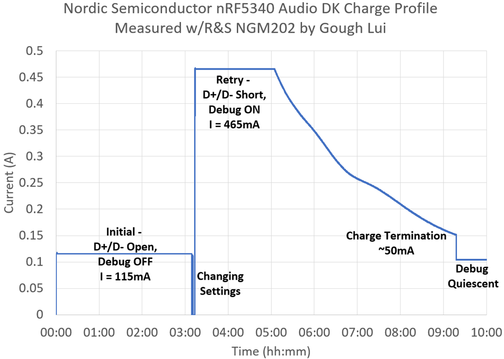
I started with the debug switch set to off for best accuracy. I did not expect, but was pleasantly surprised to find that the nPM1100 Power Management IC seems to detect and respect the USB port current limits. When first attached to my power supply through my USB adapter cable with open D+/D- lines, the PMIC took the safe option and limited current to a little more than the standard mandated 100mA level.
Once I had realised what was going on, I decided to fiddle around a bit, turning debug to on to see if that would change the current. In the end, I had to short the D+/D- lines to force detection of a dedicated charging port, and only then did the current from the USB port increase to about 465mA which is likely due to the current set resistor used in the design and consumption of the debug circuitry. Charge termination occurred with about 50mA being consumed from USB, but as the converter is switching, the actual current into the battery may be higher depending on the efficiency of the switching converter. As I didn’t have any of the small battery connectors used, I did not investigate the PMIC behaviour any further.
I grabbed my Tektronix RSA306 Real-Time Spectrum Analyser to take a look at the spectra on the air. Unfortunately, its bandwidth is not wide enough to cover the full 2.4GHz ISM band, nor do I have an adapter that will snap directly onto the SWF connector on the board, so these tests are done over-the-air with a 9dBi 2.4GHz Yagi pointed at the board at short range to minimise external influences.
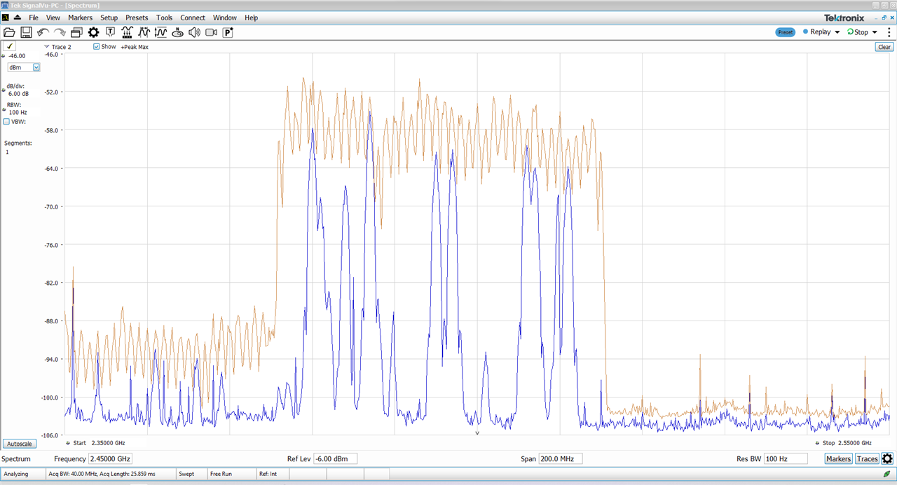
With a wide view of the spectrum, the characteristic Bluetooth channel hopping spectrum is evident. It would seem that it is compliant with the emission masks requiring -40dBc outside 2.5MHz of centre, in spite of visible noise emissions below the 2.4GHz ISM band. The advertising channels are also visible.
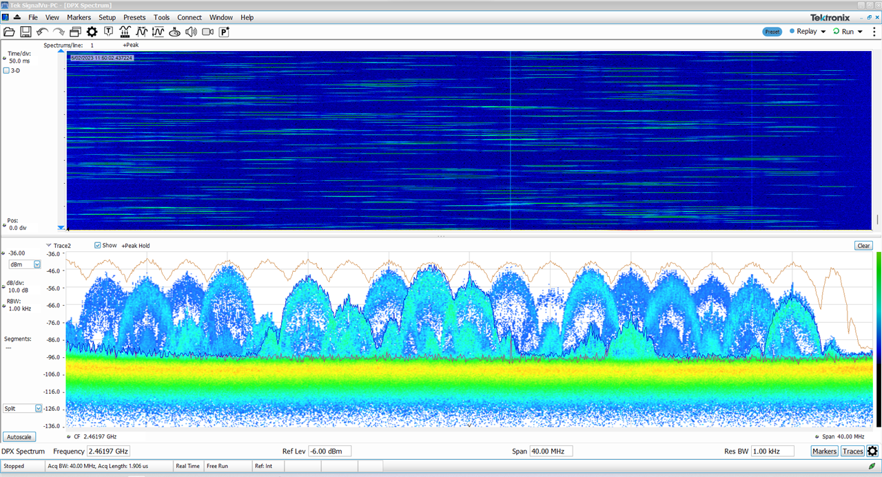
At a bandwidth where real-time spectrum analysis is possible, the hopping pattern is visible in time. Looking at the advertisement channel, it seems the emission mask requiring -26dBc at the first sidelobe is also easily met.

By flashing a headset firmware build and not having a gateway to connect to, the spectrum can be seen to be quiet, confirming that the measurements pertain to the nRF5340 Audio DK.
Unfortunately, despite trying various combinations of flags including CONFIG_BLE_LE_POWER_CONTROL_ENABLED, CONFIG_BLE_CONN_TX_POWER_NEG_*DBM and CONFIG_BLE_ADV_TX_POWER_NEG_*DBM, I was not able to elicit a change in transmit power – the spectrum analyser shows the signal strength to be the same, which explains why I was seeing the same range despite adding these flags to the build. This seems to be an issue that may arise because of some quirk with combination or ordering of flags which would be good to see fixed.
If you’re interested in just how the LC3 codec performs, then perhaps you don’t need to go all the way to a physical implementation. Instead, you could probably evaluate the codec purely in the digital space using reference or software implementations of the codecs, thus avoiding the influence of transmission and analog components (e.g. ADC/DACs).
At present, it seems Google’s liblc3 can be built from source to encode and decode from .wav files to evaluate LC3 performance. As for other Bluetooth-related codecs, ffmpeg can be built with support for SBC, AAC-LC, aptX and aptX-HD. Files can be encoded and decoded to ascertain any quality impacts under various bitrate configurations. Other codecs such as LDAC and LHDC do not have any software decoder implementations available, unfortunately, as they rely on hardware licensing income.
Alternatively, the Bluetooth Technology Website for LE Audio has an applet that will play samples encoded in different codecs at different bitrates.
The Nordic Semiconductor nRF5340 Audio Development Kit is a turn-key solution for evaluating Bluetooth Low-Energy audio with code licensed from PacketCraft and T2 Systems for use with Nordic Semiconductor SoCs. Each board comes complete with a plastic base and rechargeable Li-poly battery, although multiple boards will be required depending on the test scenario (two or more are recommended). While not inexpensive, the board itself is full of features and flexibility, including onboard current sense amplifiers for power measurement. It does feel a bit too packed with “cut open” solder jumpers so close to other components. It is also quite the showy board, with quite a few LEDs, but no quick way to isolate them. Audio-wise, it uses a Cirrus Logic mono codec which performs excellently and is economical on power, however, stereo evaluation is not possible without an additional board or off-board stereo codec. The software is also filled with various compile-time flags that can modify the build to try different settings and enable various features. The documentation was dense and sufficiently complete to get started with and gain an understanding of the code’s structure.
My experience with the board was excellent, considering this is the first time I have worked with Nordic Semiconductor SoCs and used their toolchain. While the solution is marked as experimental and there are still a few minor issues with things like reconnecting streams, forgetting volume settings and setting transmit power, the important stuff works very well. I found the LC3 codec to perform excellently, especially considering the 96kbit/s per channel bitrate, offering near-transparent audio that is better than SBC, short frame lengths that lead to low-latency in the 30-40ms range, robust packet loss concealment and a surprising level of power efficiency given the use of a “general” SoC. The Auracast broadcast mode is also well demonstrated, which will lead to new applications in public audio and perhaps even the obsolescence of low-powered FM transmitters and T-coils for hearing aids.
I would have preferred if the kit were stereo by default, could charge even when powered off and had consideration for where the battery would be located or protection for the pins which could get damaged when evaluating it in the field. Thankfully, the latter was easily addressed with a quick 3D design and print. Additionally, a more robust reconnection scheme and functional transmit power selection would also allow for better evaluation of coverage under different scenarios. It would also be interesting to see how having a front-end module to boost transmission power could increase this as well. Finally, inclusion of an NFC antenna and/or use of the microSD card beyond error logging could be potentially interesting for tap-and-pair and endless-loop audio broadcast applications, although I suppose the latter is perhaps something for the end-user to develop.
Nevertheless, it was quite an educational and enjoyable experience. Thanks to element14 and Nordic Semiconductor for giving me this opportunity to evaluate this kit.
Top Comments
I just loved the "roving mic" demo. That was much better audio quality than I would have expected from using the onboard PDM mic.
After that fantastic live news broadcast, we'll no doubt be hearing…