RoadTest: Review the ADI MAX32650FTHR Evaluation Kit and Accessories
Author: battlecoder
Creation date:
Evaluation Type: Evaluation Boards
Did you receive all parts the manufacturer stated would be included in the package?: True
What other parts do you consider comparable to this product?: "High-speed" microcontrollers like STM32, ESP8266, ESP32
What were the biggest problems encountered?: Measuring processor power consumption wasn't possible due to the supporting circuitry in the evaluation board. Connecting the debugger was also not that straightforward.
Detailed Review:
The MAX32650FTHR is a Feather-compatible Evaluation board featuring Analog Device’s MAX32650 ultra-low power microcontroller. The Kit comes with the MAX32625PICO debugger, but additionally, and for the purposes of this review, two sensor boards were included; a ADXL355 accelerometer, and a ADT7420 temperature sensor. These sensor boards have a PMOD-compatible interface instead of the "Feather" format, so I also received a FTHR-PMD-INTZ; "Feather-to-PMOD" interfacing board.
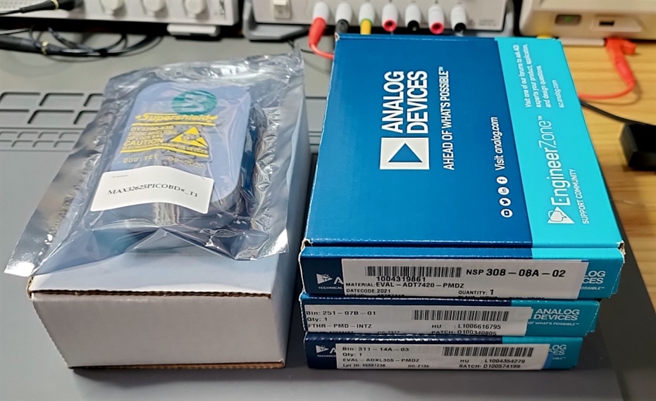
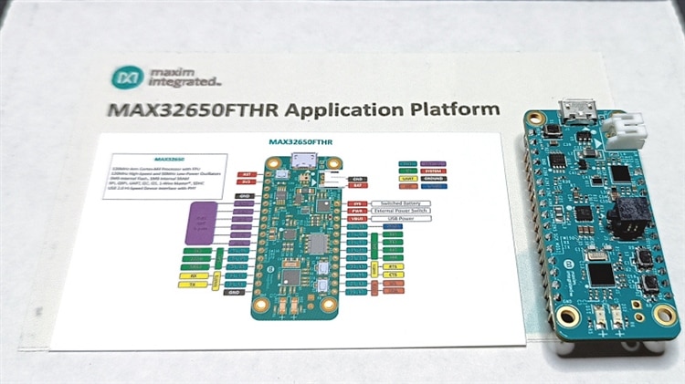
MAX32650FTHR Eval board
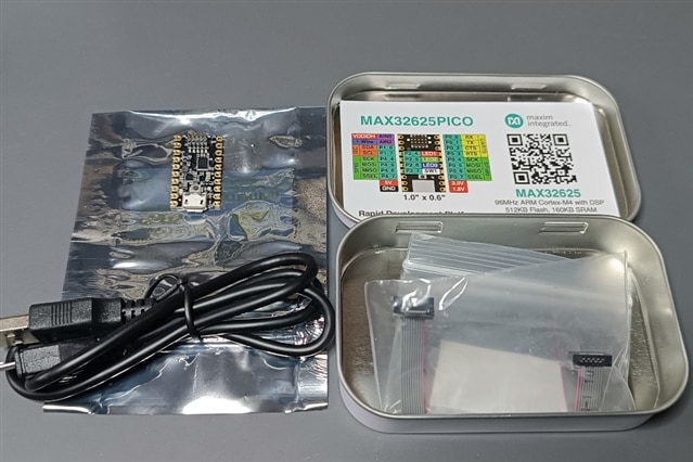
MAX32625PICO JTAG debugger/programmer
To program this board I’m following the official documentation, which in my opinion is pretty good. Here I'll be providing an overview of what it involves, and a couple of pitfalls to be aware of.
To program this board you need the Maxim Micros SDK from Analog Device’s website, which can be downloaded after creating an account on their site. The installer downloads everything you need, and it gives you the option to install a full pre-configured Eclipse IDE, as well as support for VS Code. I left both selected.
There’s a couple of broken links in the process. For example, after the installer was done, it took me to the v1.7.0 version of the VSCode-Maxim/README.md document on GitHub, from which links like the “Getting Started with Visual Studio Code” guide are broken. Checking the latest version of the same file led me to working links, and from there I was able to follow the the rest of their docs.
Following the instructions and loading an example project was super easy. I didn’t have to touch anything in Eclipse to make it work, and VS Code barely required some changes to the global settings.json to set the Maxim Micros SDK path, and at project level to select the target board, all of which are explained in the guide mentioned earlier.
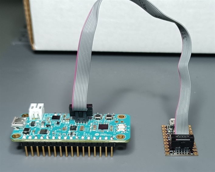
Physically connecting the debugger to the board was a bit less straightforward. The programming/debugging header is a 10-pin interface, but a 14-pin ribbon cable is supplied, that sits centered with 2 pins overhanging on each side. On top of that, the connector on the FTHR board is “keyed” (there’s only one way to insert it) but the connector on the debugging board is not.
Regardless of this, after comparing the pinouts between the diagrams of both boards I managed to correctly connect the debugger to the FTHR board and successfully upload the “Hello World” example that came with the SDK. In all fairness the actual required connections are just a couple, so a handful of jumper wires would have worked just as well.
Flashing and debugging code was easy and straightforward from both VS Code and Eclipse. Setting breakpoints and monitoring the output while it was running worked without issues.
The only problem I had, is that once I reduced the CPU clock for my tests, uploading new code required performing a manual reset of the board right before the flashing started. I assume that switching to a slower clock affected the auto-reset timing.
After a few tests I decided to download a more recent release of the debugger firmware from the MAX32625PICO GitHub repo. Updating its firmware was not required, but the procedure was easy to perform and worked without a hitch.
To measure power consumption any piece of code that keeps the processor busy should work. Microcontrollers at this range rarely have CPU throttling, or any similar mechanism to adjust power usage on their own, so probably an empty loop would suffice.
But we can do better.
The following piece of code is a simple LCG (Linear Congruential Generator) that will be calculating a sequence of pseudo-random numbers infinitely.
I added a line that will toggle an LED ON and OFF after a significant number iterations, so I know it’s actually running. At full speed that happens after >10 seconds, and I’m not measuring power consumption while the LED is ON.
I also put a flag in the code to switch to a slower clock. This is going to be important for the next section.
The Libraries folder inside the maxim SDK installation path included documentation that helped me decipher how to interact with some of the features of the processor, and it can be found at {MAXIM_SDK_INSTALL_DIR}\Libraries\PeriphDrivers\Documentation\MAX32650
Here’s where I found my first real hurdle. I wanted to perform a power consumption analysis of the processor with different clock configurations, but the many ICs on the board make that task almost impossible. There’s a couple of voltage regulators, a battery management IC, a voltage reference, the ADC, etc, and they will all draw current or have power losses.
While I can’t directly measure how much power is used by these components, I spotted another "leak" of current; The red LED on the board was kept very faintly ON, even when in its OFF state. Apparently the pin connected to it remains f̶l̶o̶a̶t̶i̶n̶g̶ (EDIT: "floating" doesn't seem to be a good description for the actual situation here. It has been pointed out in the comments that on top of VDDIOH (~3.3V) there's also a VDDIO voltage for GPIO pins of 1.8V, and this pin seems to be kept at that level), and the voltage across the diode (1.52V) is just enough to light it, albeit very dimly.
I checked with a scope, and there was no oscillation at the pin, so estimating its power consumption was technically straightforward. Using ohm’s law I got 3.25mA through the LED, so we can subtract that number from future current measurements.
But that’s the only part of the power consumption I could isolate with some degree of certainty.
I suspect that the power losses through the voltage regulators and the power drawn by the supporting ICs is probably in the same neighborhood of 3-4mA. I'm basing that estimation partially on the datasheets of the chips, but at the end of the day it's just speculation so I won't be using that figure.
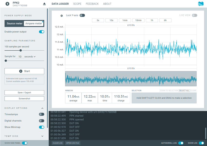
To continue with the analysis I connected the board to a Power Profiler Kit 2 from Nordic Semiconductor, using a very stable and low noise linear lab bench power supply as the power source.
Running the LCG code at 120Mhz, with the board powered through its USB port gives an average power consumption of 11mA for the entire board. Subtracting the 3.25mA of the LED, that gives us roughly 7.75mA being drawn by the processor and the supporting circuitry. Not bad at all.
If instead of powering the board through its USB connector we use the battery pins, the power consumption (at full 120MHz clock speed) goes down to 9.7mA (6.45mA subtracting the LED). By doing this we are technically bypassing the USB-related ICs, but we are making the battery management IC work. Since this is already more than 1mA less than with the USB-powered configuration, I think that my rough estimate of at least a couple of mA of power being drawn or lost by the supporting circuitry is actually reasonable.
Switching to the slower 8Khz internal clock (but back to USB power) brings the power consumption down to 8.6mA (which without the LED consumption would equal 5.35mA). I didn't notice any significant spike or erratic swings in the power consumption, even when I increased the sampling rate of my measurements.
Apart from the external chips, it’s also possible that additional configuration is required in code to truly drive the power down. The documentation lists a lot of methods to disable internal peripherals, oscillators, etc.
However, even with the extra power consumption, less than 8mA while running code at 120Mhz is extremely good. For comparison, an ESP8266 Wemos D1 (a popular board roughly in the same category) running at 80Mhz, with WIFI disabled, and with only a "USB Serial" IC and a voltage regulator on board, draws 42mA running the same code. This means that MAX32650 board uses 5 times less power than the D1 board, all while running the code at x1.5 the clock speed and providing features like accurate 6-channel analog to digital conversion and battery management thanks to the handful of chips on-board.
Obviously when it comes to microcontrollers like this one, the real low-power characteristics shine when used with minimal support circuitry and in conjunction with their sleep modes and power-saving states, but as mentioned, even at full speed and with extra supporting chips on board, the power consumption is outstandingly low.
I was, in fact, tempted to test the sleep mode, but without the ability to isolate the power consumption of the microcontroller from the rest of the board, that test would have been rather pointless.
FTHR-PMD-INTZ interface
EVAL-ADXL355-PMDZ (ADXL355 Accelerometer)
EVAL-ADT7420-PMDZ (ADT7420 Temperature Sensor)
I’ve used several temperature sensors in the past, and among the ones I’ve tested, I don’t remember any digital sensor having better than 12-bit resolution and a ±1-2°C accuracy. This is well above those specs.
I intend to write software to read at least one of the sensors myself, but before we get there it would be great to test the boards and the required connections first.
Fortunately, there's wiki articles for both modules, which include pre-built demo binaries for a couple of boards, including the MAX32650FHTR
Unfortunately, the direct links to the binary files in the wiki are broken, although it wasn't hard to browse the repository, find the latest releases, and download the files, which as the time of writing are:
Broken GitHub links are probably due to the way repositories keep getting reorganized and restructured, so this could happen to any project with documentation pointing directly to files hosted on a source-control system.
Apart from obtaining the pre-compiled binary files, I had to replace the pin headers in my Feather board with long through-hole female headers, so I could connect the FTHR-PMD-INTZ board on top of it, as the wiki shows.
I didn't have headers with the right number of pins, so I had to create my own using a couple of shorter ones, sanding down the shared edges of the plastic housings so they had the correct spacing.
It's not pretty but it works.
 |
 |
Now it was just a matter of uploading the code to the board and trying the demos, both of which worked without a problem.
| {gallery}Sensor demo screenshots |
|---|
|
Accelerometer Demo: Console output of the pre-built binary of the ADXL335 accelerometer demo |
|
Temperature Sensor Demo: Console output of the pre-built binary of the AD7420 temperature sensor demo |
After running the pre-built demos, and verifying that the interface and the sensors work, I decided to program something to get temperature readings from the ADT7420 directly from code, since the previous pre-built binary demo is not something we can use in a project.
The ADT7420 is an I2C sensor, so I went over the SDK documentation for the I2C methods, as well as the ADT7420 datasheet to understand how to interact with the sensor through the I2C bus.
I'm not using any of the fancy triggering or alert modes of the chip, just the "continuous" temperature reading mode. Having said that, I'm setting the resolution to 16 bits.
Not that I need it, but it's a good way to test that we can write (not only read) to the device.
Here's the code I wrote that initializes the sensor in 16 bits resolution, and then reads the temperature every second:
And its output looks like this:

Note that the first reading is off by a bit, compared to the rest of them. The ADT7420 datasheet offers an explanation for this:
"On power-up, the first conversion is a fast conversion, taking typically 6 ms".
Considering that "normal" readings take 1/4 of a second, the accuracy of something done in only 6ms can't be on par with the rest. I actually love that this sensor provides a fast reading on power-up. I've lost count of the many times I had to add a delay in my projects after setting up the hardware, just to give time for the sensors to be ready.
So our code is working perfectly fine, and the only challenge was figuring out how to use the I2C methods found in the SDK. There's plenty of ways of accessing the I2C bus, from async methods, direct access to the TX/RX FIFO queues, low level I2C bus manipulation, etc, and I played with some of them before getting to something that worked and was straightforward enough.
This didn't take more than a couple of hours though, so I'd say it was easier than I expected.
The Good
The Bad
Overall
The board is extremely powerful and it truly exhibits a low power consumption like no other board I've used in the past. Coding with the provided SDK is easy, but it requires extensive reading through included documentation and datasheets. This might be a problem for some people, but par for the course for others.
I also wish there was an easy option to isolate the microcontroller or bypass the supporting chips in order to truly evaluate its low-power characteristics, but I guess people interested in ultra low-power applications will be designing their own boards fully tailored to their specific needs anyway.
All in all, I think this is an outstanding microcontroller for low-power embedded designs, and the MAX32650FTHR evaluation board offers a fantastic way of testing the chip, as well as prototyping with it. The tools and documentation supplied by the manufacturer are also pretty good, and more than enough to get users started with this great microcontroller.


Top Comments
Here is schematic of LED connection:
I think there is different problem.
Floating pins (Hi-Z) do not allow source or sink currents except leak insufficient to lit LED (even lightly). But Maxim MCU supports…
Agreed. measure voltage across R5 and divide by 470 to get the current. This may help to work out why there is any current.
MK
I do appreciate this discussion. I actually wasn't sure if it was correct to add that statement about the LED, however I checked some LED datasheets and at 1.52V most of them were pretty much in full conduction…