element14 Community
element14 Community
    Register Log In
  • Site
  • Search
  • Log In Register
  • About Us
  • Community Hub
    Community Hub
    • What's New on element14
    • Feedback and Support
    • Benefits of Membership
    • Personal Blogs
    • Members Area
    • Achievement Levels
  • Learn
    Learn
    • Ask an Expert
    • eBooks
    • element14 presents
    • Learning Center
    • Tech Spotlight
    • STEM Academy
    • Webinars, Training and Events
    • Learning Groups
  • Technologies
    Technologies
    • 3D Printing
    • FPGA
    • Industrial Automation
    • Internet of Things
    • Power & Energy
    • Sensors
    • Technology Groups
  • Challenges & Projects
    Challenges & Projects
    • Design Challenges
    • element14 presents Projects
    • Project14
    • Arduino Projects
    • Raspberry Pi Projects
    • Project Groups
  • Products
    Products
    • Arduino
    • Avnet Boards Community
    • Dev Tools
    • Manufacturers
    • Multicomp Pro
    • Product Groups
    • Raspberry Pi
    • RoadTests & Reviews
  • Store
    Store
    • Visit Your Store
    • Choose another store...
      • Europe
      •  Austria (German)
      •  Belgium (Dutch, French)
      •  Bulgaria (Bulgarian)
      •  Czech Republic (Czech)
      •  Denmark (Danish)
      •  Estonia (Estonian)
      •  Finland (Finnish)
      •  France (French)
      •  Germany (German)
      •  Hungary (Hungarian)
      •  Ireland
      •  Israel
      •  Italy (Italian)
      •  Latvia (Latvian)
      •  
      •  Lithuania (Lithuanian)
      •  Netherlands (Dutch)
      •  Norway (Norwegian)
      •  Poland (Polish)
      •  Portugal (Portuguese)
      •  Romania (Romanian)
      •  Russia (Russian)
      •  Slovakia (Slovak)
      •  Slovenia (Slovenian)
      •  Spain (Spanish)
      •  Sweden (Swedish)
      •  Switzerland(German, French)
      •  Turkey (Turkish)
      •  United Kingdom
      • Asia Pacific
      •  Australia
      •  China
      •  Hong Kong
      •  India
      •  Korea (Korean)
      •  Malaysia
      •  New Zealand
      •  Philippines
      •  Singapore
      •  Taiwan
      •  Thailand (Thai)
      • Americas
      •  Brazil (Portuguese)
      •  Canada
      •  Mexico (Spanish)
      •  United States
      Can't find the country/region you're looking for? Visit our export site or find a local distributor.
  • Translate
  • Profile
  • Settings
Code Exchange
  • Technologies
  • More
Code Exchange
Forum Code for small diy clock kits.
  • Blog
  • Forum
  • Documents
  • Events
  • Polls
  • Files
  • Members
  • Mentions
  • Sub-Groups
  • Tags
  • More
  • Cancel
  • New
Join Code Exchange to participate - click to join for free!
Actions
  • Share
  • More
  • Cancel
Forum Thread Details
  • State Suggested Answer
  • Replies 36 replies
  • Answers 18 answers
  • Subscribers 49 subscribers
  • Views 8425 views
  • Users 0 members are here
  • mod
  • clock
  • at89
  • Code Exchange
  • attiny 2313
  • diy
  • assembly_language
Related

Code for small diy clock kits.

fbtjbt
fbtjbt over 7 years ago

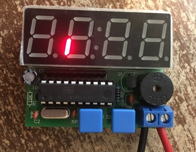
I've been looking for a project that would be suitable for young Boy Scouts, and have decided that one of these DIY clock kits would be something that even the youngest could put together.

imageimage

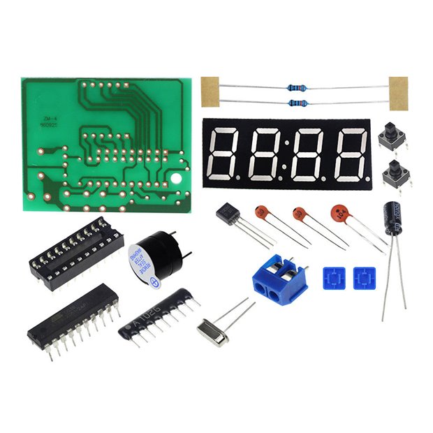
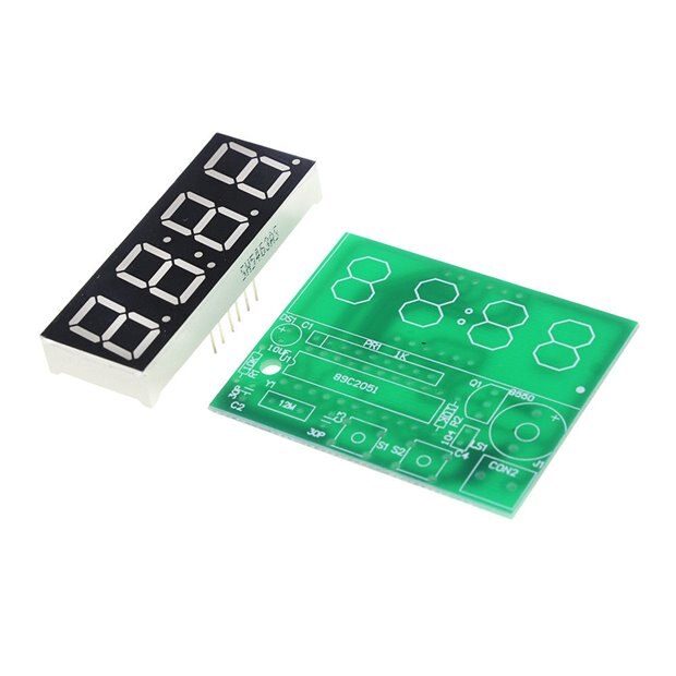
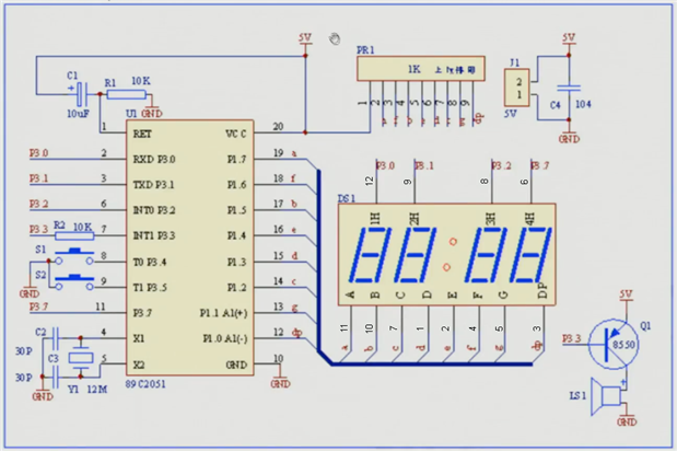
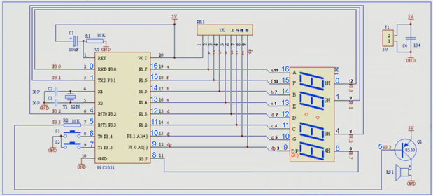
Most of the kits appear to come with an AT89C2051 (they all seem to come with the same pcb as well), so I've also searched out code that the older scouts could program additional AT89C2051s with. I'll reach out to the local university to see if they've got a programmer that we can use, but the boys won't have access to one after we're done making these. I think having a couple extra chips to swap around with different programs would be cool to them.


The clock comes with a standard clock program, but I'm still looking for a simple countdown timer and a simple stopwatch. By "simple" I mean something that I can show the scouts, and explain commented snippets of the code.

The code that I've found has been on forums where the members haven't been active for years, so I can't ask them followup questions.


If anyone could help me out with simplified code for two projects, I would greatly appreciate it. I can reassign pins in the code if the boards end up being pinned slightly different than what is pictured (you never know with these things).


Countdown Timer:

- button1 == cancel timer / cancel buzzer

- button2 == add time to countdown

- button1 held >2sec == enter/exit setup mode.

- button1 in setup mode == toggle buzzer duration between: 60sec / 300sec / 600sec / 9999sec

- button2 in setup mode == toggle button2 "value" between: 30sec / 60sec / 180sec / 240sec / 300sec

Timer counts down in seconds from 9999 - 0 (in base10)

Digits blink at 500ms intervals while <=10sec

Button2 push adds value to current countdown at any time

Buzzer sounds at 500ms interval.


Stopwatch:

- button1 == clear

- button2 == start/pause

- button1 + button2 == switches between hh:mm / mm:ss / ss:ms ("Hr:  " / " :S " / " S:  ")

Time counts up (in base 60)

Time stops at 99:59 (i.e. 99hr:59min / 99min:59sec / 99sec:59ms)


I think there are some good learning opportunities between the two programs. Showing them the code and having them customize values in their code (like the available "values" for button1&2) will help them feel ownership in the project.


TheCustomGeek shared some code for one of his projects, and is what I used as the base for my attempts to make the Countdown Timer and Stopwatch described above. Here's a link Multiplexing for a 7 year old | The Custom Geek

I've attached the code, too, mainly so that the multiplexing can be similar in both projects (easier to explain to the scouts). Using a better method is fine too.  I've removed this, and attached the assembly code that I had initially started with -prior to finding TheCustomGeek's project. We do have access to a C compiler and linker for the 8051s (AT89C2051 included), though.


I'm still muddling through this on my own, but I'm hoping that one (or more) of you would be able to put together some code much faster/better/cleaner than I.

Attachments:
Countdown Timer.a51.txt.zip
  • Sign in to reply
  • Cancel

Top Replies

  • michaelkellett
    michaelkellett over 7 years ago in reply to shabaz +4 suggested
    The atTiny2313A is a supported product of Atmel/Microchip in current production. It's a way better part than the 8051 based one. Atmel Studio 7 supports it and gives you a free C compiler and debugger…
  • michaelkellett
    michaelkellett over 7 years ago in reply to fbtjbt +4 suggested
    I had some free Paypal money (from "Have a beer" promotion on Embedded related") so I just ordered 2 of these: https://www.ebay.co.uk/itm/282484911382?ViewItem=&item=282484911382 I'll try re-hearting one…
  • shabaz
    shabaz over 7 years ago in reply to fbtjbt +3 suggested
    That's assembler code, which is likely what you'll need to do for the AT89C2051, unless you can find a C compiler and linker (I have no idea if that is practical for that chip, and it will require some…
Parents
  • shabaz
    0 shabaz over 7 years ago

    Hi,


    The attached code is for an Arduino, which contains a different microcontroller compared to AT89C2051. The code isn't compatible.

    You could rewrite the code for AT89C2051, but you'd almost have to start from scratch, since even the LED display is different, yours appears to have 12 pins, and the one that the Arduino code is for has 16 pins, so yours is multiplexed differently, and that would need to be deciphered too. So, a non-trivial exercise to do this, but possible.

    The AT89C2051 is a really ancient chip, so although you'll likely find information on the Internet on how to program it and perhaps some example programs to get you started, personally I don't have any example source code for this microcontroller - I think I maybe briefly used it >10 years ago. Personally I wouldn't advise it, because you'll need to source a programmer and compiler, and most of this is really ancient as mentioned. Better to just have a construction project with it using the pre-programmed chip supplied with the kit perhaps, and have a different project if you want to demonstrate different code.

    • Cancel
    • Vote Up +2 Vote Down
    • Sign in to reply
    • Verify Answer
    • Reject Answer
    • Cancel
  • fbtjbt
    0 fbtjbt over 7 years ago in reply to shabaz

    Dangit. I had started this project using code from one of those other groups that I mentioned, but then started looking for other code after a while. TheCustomGeek code was more 'legible' to me, so that's when I pivoted. Here is what I was working with before (see attached txt).

    Attachments:
    1856.Countdown Timer.a51.txt.zip
    • Cancel
    • Vote Up +1 Vote Down
    • Sign in to reply
    • Verify Answer
    • Cancel
  • fbtjbt
    0 fbtjbt over 7 years ago in reply to michaelkellett

    I ordered a different programmer that I saw in a video on youtube. It should be here this weekend/monday. I've modified code for a "multiplexing" clock to (hopefully) work with the pinout of the DIY Clock, so I can try it out once the programmer gets here.

    As long as it works, I can start messing with code for the two projects above.

    How goes the Countdown Timer?

    • Cancel
    • Vote Up 0 Vote Down
    • Sign in to reply
    • Verify Answer
    • Reject Answer
    • Cancel
  • michaelkellett
    0 michaelkellett over 7 years ago in reply to fbtjbt

    My own playing has not gone well - lack of time so zero progress since Feb25th image


    MK

    • Cancel
    • Vote Up +1 Vote Down
    • Sign in to reply
    • Verify Answer
    • Cancel
  • fbtjbt
    0 fbtjbt over 7 years ago in reply to michaelkellett

    The rest of my kit came in, and everything is assembled, so my first attempt is to get the display working with a simple program.

    It turns out that the schematic associated with the clock is incorrect. I've updated the schematic below with the display pin numbers to match the PCB layout.

    I haven't been able to verify that the segment order is correct, nor if the digit order is correct, because I'm still trying to wrap my head around how it works using sip resistors.


    Would you turn OFF the segments by setting the segment pins LOW (and digit pins HIGH) to pull the 5v away from the display?

    Then set the digit pin LOW to select the digit, and the segment pin HIGH to divert the 5v back to the segment?


    image


    EDIT: I've confirmed a few of the display pinouts (above), so I'd imagine that the rest are correct also.


    I've gotten to the point where I can blink the display ONCE (without control over duration) then the display becomes unresponsive.

    - Setting the digit pins to HIGH, and the segment pins to LOW disables the display.

    - Setting pin0 (digit pin 12) to LOW, and pin10 (segment pin 5 'g') to HIGH gives me a short "-"blink.

    - Setting pins 0, 1, 4 & 8 (digit pins 12, 9, 8 & 6) to LOW, and pin10 (segment pin 5 'g') to HIGH gives me a short "----"blink.


    I still don't fully understand how to drive the display when using pull-up resistors on the segment pins.

    Am I right in that HIGH=SOURCE and LOW=SINK?

    Or do you need to use LOW to SINK (divert power), then "FLOAT" the segment pins to allow the LED to pull power through the 1K resistor array?

    • Cancel
    • Vote Up +1 Vote Down
    • Sign in to reply
    • Verify Answer
    • Cancel
  • fbtjbt
    0 fbtjbt over 7 years ago in reply to gadget.iom

    At my nephew's request (one of the Boy Scouts that I will eventually be instructing), I have also started experimenting with ArduinoIDE.


    I've simplified the schematic for the boys who are new-to-electronics, and added ArduinoPinNumbers in Blue:

    (note that the cathode for dp is digit2, the dp anode lights all segments [making a dim "8"] when digit 1, 3, or 4 cathodes are connected.)


    image


    My limited experience leads me to believe that this should blink "-" on digit one, but it doesn't repeat:


    int segmentPins[8] = {16, 15, 14, 13, 12, 11, 10, 9};    // SEGMENTS A11, F10, B7, E1, D2, C4, G5, DP3

    int digitPins[4] = {0, 1, 4, 8};                                        // DIGITS (1)12, (2)9, (3)8, (4)6


    void setup() {

      for(int i=0; i < 8; i++) {

        pinMode(segmentPins[i], OUTPUT);   // SET SEGMENT PINS TO GND:  OUTPUT+LOW = SINK 5V / INPUT=ON

        digitalWrite(segmentPins[i], LOW);

      }

      for(int i=0; i < 4; i++) {

        pinMode(digitPins[i], OUTPUT);     // SET DIGIT PINS TO GND: OUTPUT+LOW = ON

        digitalWrite(digitPins[i], LOW);

        pinMode(digitPins[i], INPUT);        // TURN OFF DIGIT PINS: INPUT=OFF

      }

    }


    void loop() {

    //  delay(2000);                       // doesn't blink the segment when this is enabled

      pinMode(0, OUTPUT);      // DIGIT1 cathode to GND

      pinMode(10, INPUT);       // un-ground SEGMENT 'g' allowing 5v

      delay(500);                       // wait a half second

      pinMode(10, OUTPUT);   // ground SEGMENT 'g' diverting 5v

      pinMode(0, INPUT);         // DIGIT1 cathode to INPUT

      delay(500);                       // wait a half second

    }

    • Cancel
    • Vote Up 0 Vote Down
    • Sign in to reply
    • Verify Answer
    • Cancel
  • michaelkellett
    0 michaelkellett over 7 years ago in reply to fbtjbt

    In your dash blinking loop I think you need a delay between un-grounding and grounding so that the segment has some time on.


    MK

    • Cancel
    • Vote Up 0 Vote Down
    • Sign in to reply
    • Verify Answer
    • Reject Answer
    • Cancel
  • fbtjbt
    0 fbtjbt over 7 years ago in reply to michaelkellett

    Thanks for catching that. I missed that line while I was typing it here on the forum (now edited to include it).

    I started out using the standard 1000ms delay for the on/off, but the led only flashed once for about 250ms then..... nothing.


    It doesn't blink at all when I put a delay(2000); at the beginning of the void loop.

    • Cancel
    • Vote Up 0 Vote Down
    • Sign in to reply
    • Verify Answer
    • Cancel
  • jc2048
    0 jc2048 over 7 years ago in reply to fbtjbt

    https://www.arduino.cc/reference/en/language/functions/digital-io/pinmode/


    "Notes and Warnings

    The analog input pins can be used as digital pins, referred to as A0, A1, etc."

    • Cancel
    • Vote Up 0 Vote Down
    • Sign in to reply
    • Verify Answer
    • Cancel
  • fbtjbt
    0 fbtjbt over 7 years ago in reply to jc2048

    I was using this as a reference for the 4313 ArduinoIDE pinout:

    image

    Am I using the pinMode() incorrectly for this chip?

    • Cancel
    • Vote Up 0 Vote Down
    • Sign in to reply
    • Verify Answer
    • Cancel
  • jc2048
    0 jc2048 over 7 years ago in reply to fbtjbt

    I don't know.


    I was just going by the processor pin-out you showed further up. Pin 13 can function as an input to the A/D, so maybe it's treated differently in the same way as would be the case with the analog pins on an Arduino.


    I was just suggesting it as something you could try.

    • Cancel
    • Vote Up 0 Vote Down
    • Sign in to reply
    • Verify Answer
    • Cancel
  • mcb1
    0 mcb1 over 7 years ago in reply to fbtjbt

    Am I using the pinMode() incorrectly for this chip?

    Short answer NO.


    PinMode() sets the function of the pin


    Input (floating) or with Pullup or Pulldown

    Output either HIGH or LOW


    int segmentPins[8] = {16, 15, 14, 13, 12, 11, 10, 9};
    // SEGMENTS A11, F10, B7, E1, D2, C4, G5, DP3
    
    int digitPins[4] = {0, 1, 4, 8};                     
    // DIGITS (1)12, (2)9, (3)8, (4)6
    
    void setup() {
      for(int i=0; i < 8; i++) {
         pinMode(segmentPins[i], OUTPUT);   // SET SEGMENT PINS TO GND:  OUTPUT+LOW = SINK 5V / INPUT=ON
         digitalWrite(segmentPins[i], LOW);
      }
    
      for(int i=0; i < 4; i++) {
         pinMode(digitPins[i], OUTPUT);        // SET DIGIT PINS TO GND: OUTPUT+LOW = ON
         digitalWrite(digitPins[i], LOW);
         pinMode(digitPins[i], INPUT);         // TURN OFF DIGIT PINS: INPUT=OFF
      }
    }
    
    void loop() {
    
    //  delay(2000);                   
    // doesn't blink the segment when this is enabled
      pinMode(0, OUTPUT);    // DIGIT1 cathode to GND
      pinMode(10, INPUT);    // un-ground SEGMENT 'g' allowing 5v
      delay(500);            // wait a half second.  
      pinMode(10, OUTPUT);   // ground SEGMENT 'g' diverting 5v
      pinMode(0, INPUT);     // DIGIT1 cathode to INPUT
      delay(500);            // wait a half second
    }


    Lines 07 to 11 set the pins to be outputs. These will always be LOW, but it doesn't hurt to do the digitalWrite LOW.


    Lines 13 to 17 seem to firstly set the pins to Outputs and write them low, then set them as a floating input.

    Since these are the common cathode of the display, they will be an Output, hence line 16 should be removed.


    When you get to your loop, you are not setting the state of the pins, you are simply redefining their function.

    If you want to illuminate segment g, then you need to set Pin10 to HIGH, and Pin 0 to LOW


    hence the loop would look more like this

    void loop() {
    
    //  delay(2000);                   
    // doesn't blink the segment when this is enabled
      DigitalWrite(0, LOW);  // DIGIT1 cathode to GND
      DigitalWrite(0, HIGH);   // un-ground SEGMENT 'g' allowing 5v
      delay(500);           // wait a half second.  
      DigitalWrite(0, HIGH);     // DIGIT1 cathode to INPUT
      DigitalWrite(0, LOW);   // ground SEGMENT 'g' diverting 5v
      delay(500);            // wait a half second
    }


    This should cause segment g of the end display to blink.


    HOWEVER THIS IS IMPORTANT

    You have an output supplying current into the segments, so you will need some resistance OR use a diode to simply short out the 5v fed via the 1k resistor.

    IMO remove the PR1 and add 1K resistors between the controller pin and the segments.


    Mark

    BTW you can add code and select the >> and Syntax Highlighting C++ to get it looking like the above

    • Cancel
    • Vote Up +1 Vote Down
    • Sign in to reply
    • Verify Answer
    • Cancel
Reply
  • mcb1
    0 mcb1 over 7 years ago in reply to fbtjbt

    Am I using the pinMode() incorrectly for this chip?

    Short answer NO.


    PinMode() sets the function of the pin


    Input (floating) or with Pullup or Pulldown

    Output either HIGH or LOW


    int segmentPins[8] = {16, 15, 14, 13, 12, 11, 10, 9};
    // SEGMENTS A11, F10, B7, E1, D2, C4, G5, DP3
    
    int digitPins[4] = {0, 1, 4, 8};                     
    // DIGITS (1)12, (2)9, (3)8, (4)6
    
    void setup() {
      for(int i=0; i < 8; i++) {
         pinMode(segmentPins[i], OUTPUT);   // SET SEGMENT PINS TO GND:  OUTPUT+LOW = SINK 5V / INPUT=ON
         digitalWrite(segmentPins[i], LOW);
      }
    
      for(int i=0; i < 4; i++) {
         pinMode(digitPins[i], OUTPUT);        // SET DIGIT PINS TO GND: OUTPUT+LOW = ON
         digitalWrite(digitPins[i], LOW);
         pinMode(digitPins[i], INPUT);         // TURN OFF DIGIT PINS: INPUT=OFF
      }
    }
    
    void loop() {
    
    //  delay(2000);                   
    // doesn't blink the segment when this is enabled
      pinMode(0, OUTPUT);    // DIGIT1 cathode to GND
      pinMode(10, INPUT);    // un-ground SEGMENT 'g' allowing 5v
      delay(500);            // wait a half second.  
      pinMode(10, OUTPUT);   // ground SEGMENT 'g' diverting 5v
      pinMode(0, INPUT);     // DIGIT1 cathode to INPUT
      delay(500);            // wait a half second
    }


    Lines 07 to 11 set the pins to be outputs. These will always be LOW, but it doesn't hurt to do the digitalWrite LOW.


    Lines 13 to 17 seem to firstly set the pins to Outputs and write them low, then set them as a floating input.

    Since these are the common cathode of the display, they will be an Output, hence line 16 should be removed.


    When you get to your loop, you are not setting the state of the pins, you are simply redefining their function.

    If you want to illuminate segment g, then you need to set Pin10 to HIGH, and Pin 0 to LOW


    hence the loop would look more like this

    void loop() {
    
    //  delay(2000);                   
    // doesn't blink the segment when this is enabled
      DigitalWrite(0, LOW);  // DIGIT1 cathode to GND
      DigitalWrite(0, HIGH);   // un-ground SEGMENT 'g' allowing 5v
      delay(500);           // wait a half second.  
      DigitalWrite(0, HIGH);     // DIGIT1 cathode to INPUT
      DigitalWrite(0, LOW);   // ground SEGMENT 'g' diverting 5v
      delay(500);            // wait a half second
    }


    This should cause segment g of the end display to blink.


    HOWEVER THIS IS IMPORTANT

    You have an output supplying current into the segments, so you will need some resistance OR use a diode to simply short out the 5v fed via the 1k resistor.

    IMO remove the PR1 and add 1K resistors between the controller pin and the segments.


    Mark

    BTW you can add code and select the >> and Syntax Highlighting C++ to get it looking like the above

    • Cancel
    • Vote Up +1 Vote Down
    • Sign in to reply
    • Verify Answer
    • Cancel
Children
  • fbtjbt
    0 fbtjbt over 7 years ago in reply to mcb1

    Thanks for responding! I saw your post as I was getting ready to post more info about the project.

    I, too, would have gone a different route with the pcb design if I were doing this from scratch. I'm stuck with PR1 because that's the way the board comes.


    I setup a breadboard to mimic the way the DIY Clock display is set up. I didn't have a sip resistor array, so I put 1k resistors from the +rail to the LED/controller.

    Yellow is attached to Digit1 cathode,

    Green is attached to Digit2 cathode,

    Blue is attached to Digit3 cathode,

    Reds are attached to Digit4 cathode,

    and they are attached to 6 different anodes.

    image


    This bit of code works to blink the "segments" (in a charliplexing-sort-of-way) on the breadboard:


    //
    //  Common Cathode with Sip Resistors
    //
    //  Created: Mar 26, 2018 4:05 PM
    //  Author: Flibity Jibbet
    //
    
    
    int segmentPins[8] = {10, 15, 13, 12, 11, 14, 16, 9}; // Map Segment Anodes G5, F10, E1, D2, C4, B7, A11, DP3
    int digitPins[4] = {0, 1, 4, 8}; // Map Digit Cathodes (1)12, (2)9, (3)8, (4)6
    
    
    void setup() {
      pinMode(5, OUTPUT); // set Buzzer
        digitalWrite(5, HIGH);  //set Buzzer OFF
      pinMode(6, INPUT);  // set LEFT Button
      pinMode(7, INPUT);  // set RIGHT Button
      for(int i=0; i < 8; i++) {
        pinMode(segmentPins[i], OUTPUT);  // sink SEGMENT pin +5v 1Kohm resistor (pin is INPUT on powerup)
      }
    }
    
    
    void loop() {
      for(int g=0; g < 4; g++) {
        pinMode(digitPins[g], OUTPUT);     // sink DIGIT cathode
        for(int i=0; i < 7; i++) {
          pinMode(segmentPins[i], INPUT);  // float SEGMENT pin
          delay(50);
          pinMode(segmentPins[i], OUTPUT);  // sink SEGMENT pin +5v 1Kohm resistor
        }
        pinMode(digitPins[g], INPUT);      // float DIGIT cathode
      }
    }


    I ran into a problem when I put the 4313 back in the DIY Clock, though. It blips the first segment, then appears to crash.

    A check over the schematics showed that the DIY Clock has a 10k resistor @ R1, which my breadboard didn't have.

    As soon as I removed R1, the code worked! It happily drives the Common Cathode display using Sip resistors.


    I seriously can't believe how much time it has taken to reverse engineer this little clock, then to write code that only tests the segments of the display.

    Nearly a month of evenings into this project, and I haven't gotten to the "Countdown Timer" or "Stopwatch" programs that I initially posted about... image

    I can only imagine how much time my Boy Scout leaders spent learning a skill just so that they could teach it to me and the other boys.


    Now, on to the next steps.

    I'd still love any assistance or pointers on how best to code the two programs in the original post.


    WooHoo!!!

    image

    • Cancel
    • Vote Up +1 Vote Down
    • Sign in to reply
    • Verify Answer
    • Reject Answer
    • Cancel
  • michaelkellett
    0 michaelkellett over 7 years ago in reply to fbtjbt

    Here (at last) is my code to make the little Chinese board work like a stop watch using an atTiny4313 processor. Only one modification is required to the board (remove the big capacitor connected to pin 1 for reset) because I wanted to be able to use the debugWIRE interface.

    I had an Atmel JTAGICEMk2 available so I used that - there are many other debug interfaces you can use, some of them much cheaper.

    I used Atmel Studio7 which is  a free download and the code is written in C.

    I hope there is enough comment in the code for you to understand how it works - if not them please ask.

    The left hand button is a reset and the right hand stops and  starts the stopwatch function. I set the processor fuses to use the 8MHz on chip RC oscillator rather than the external crystal.

    There is support for the decimal points in the display driver function but I have not used it in the code.


    /*
     * GccApplication1.c
     *
     * Created: 14/02/2018 10:19:38
     * Author : Michael Kellett
     */ 
    
    #include 
    #include 
    #include 
    #include 
    
        // PINS 
        //    1    RES                                        
        //    2    PD0    CC0 HEX DIGIT 0 COMMON CATHODE
        //    3    PD1    CC1 HEX DIGIT 1 COMMON CATHODE
        //    4    PA1 XTAL
        //    5    PA0 XTAL
        //    6    PD2    CC2 HEX DIGIT 2 COMMON CATHODE
        //    7    PD3 SOUNDER
        //    8    PD4 S1
        //    9    PD5    S2
        //    10    GND
        //    11    PD6    CC3 HEX DIGIT 3 COMMON CATHODE
        //    12    PB0    dp ANODE
        //    13    PB1    g ANODE
        //    14    PB2    c ANODE
        //    15    PB3    d ANODE
        //    16    PB4    e ANODE
        //    17    PB5    b ANODE
        //    18    PB6    f ANODE
        //    19    PB7    a ANODE
        //    20    V+ SUPPLY
        
        // The LED display is wired so that the segment anodes are pulled high by resistors and the common cathodes pulled low by PD0,1,2 and 6.
        // To drive the display we select a digit by setting its common cathode port pin to output, low and control segments by setting their port pins to input for on out output, low for off.
        //
    
    
    // VARIABLES
    const uint8_t digit_select[4] = {1,2,4,64};
    const uint8_t digit_codes[10] = {0xfc,0x24,0xba,0xae,0x66,0xce,0xde,0xa4,0xfe,0xee};
    uint8_t timer[4] = {0,0,0,0};
    uint8_t timer_buf[4] = {0,0,0,0};
    volatile uint32_t debug_counter = 0;
    uint16_t seconds_timer = 0;
    uint16_t second_count = 1000;
    volatile bool new_second = false;
    volatile bool overflow = false;
    volatile bool new_timer = false;
    volatile bool timer_enabled = false;
    
    uint8_t btn_up_time[2] = {0,0};
    volatile bool btn_press[2] = {false,false};
    
    // LOCAL FUNCTION DECLARATIONS
    
    void add_second(void);
    void do_buttons(void);
    
    // LOCAL DEFINITIONS
    
    #define BTN_UP_MIN    20    // button debounce time, must have been released for 20 ms to register a press
    #define S1            0    // reset button on left
    #define S2            1    // stop start button on right
        
    
    int main(void)
    {
    
    wdt_disable();
        
    DDRB = 0x00;            // this is the default but it doesn't hurt to be sure, all segments as inputs
    DDRD = 0x08;            // sounder as output, all else as inputs
    PORTD = 0x38;            // pull ups on the switch pins activated, sounder off
    PORTB = 0x00;            // all segment drives low (when set as outputs)
    
    TCCR1A = 0;
    TCCR1B = 0x01;            // timer in timer mode, clock full speed
    TIMSK = 0x80;            // mask for overflow is enabled
    
    sei();                    // clear global interrupt mask
        
    while (1)
        {
        debug_counter++;                // so we can tell if the main loop is running correctly    
        if (btn_press[S1] == true)        // reset button
            {
            timer_enabled = false;        // if you hit reset timing is over
            timer[0] = 0;
            timer[1] = 0;
            timer[2] = 0;
            timer[3] = 0;                // count is reset
            btn_press[S1] = false;
            new_timer = true;
            }
        else
            {
            if (timer_enabled == true)
                {
                if (btn_press[S2] == true)
                    {
                    timer_enabled = false;
                    }
                }
            else
                {
                if (btn_press[S2] == true)
                    {
                    timer_enabled = true;
                    }
                }
            }
        btn_press[S2] = false;            // don't to see same press twice
        
        if (new_second == true)
            {
            new_second = false;
            add_second();    
            new_timer = true;            
            }    
        }
        
        
    }
    
    void drive_digit(uint8_t digit, uint8_t value, uint8_t dp)
    {
    uint8_t temp;
    
    if (digit > 9) digit = 9;
    if (value > 9) value = 9;
    if (dp > 1) dp = 1;
    
    temp = DDRD;                        // use a temp so there is no intermediate value in DDRD
    temp &= 0xb8 ;                        // set all the digit select DDRD bits to zero
    temp |= digit_select[digit];        // set the digit select DDRD bit for this digit to 1
    DDRD = temp;                        // actually write to the register
    
    DDRB = ~digit_codes[value + dp];    // set any segments to be off as output
    }
    
    ISR(TIMER1_OVF_vect)                // timer interrupt, set for 1ms interrupts
    {
    static uint8_t digit = 0;
    uint8_t i;
    
    TCNT1 = 0xe000;                        // we are using 8MHz clock, this gives us 8192 counts per ms which is close enough
                                        // a really fun exercise is to work out how to calibrate the timing by varying the 
                                        // value loaded into TCNT1
    
    drive_digit(digit, timer_buf[digit], 0);
    digit++;
    digit &= 3;
    if ((digit == 0)&&(new_timer == true))
        {
        for(i = 0; i < 4; i++)
            {
            timer_buf[i] = timer[3 - i];        
            } 
        new_timer = false;
        }
    if (timer_enabled == true)
        {        
        seconds_timer++;
        if (seconds_timer == second_count)
            {
            seconds_timer = 0;
            new_second = true;
            }
        }
    do_buttons();
    }
    
    void add_second(void)
    {
    timer[0]++;
    if (timer[0] == 10)    
        {
        timer[1]++;
        timer[0] = 0;
        }
    if (timer[1] == 6)
        {
        timer[2]++;
        timer[1] = 0;
        }
    if (timer[2] == 10)
        {
        timer[3]++;
        timer[2] = 0;
        }
    if (timer[3] == 10)
        {
        timer[3] = 0;
        overflow = true;
        }
    }
    
    
    void do_buttons(void)
    {
    uint8_t btn = 0;
    const uint8_t btn_mask[2] = {0x10,0x20};
        
    for(btn = 0; btn < 2; btn++)
        {
        if ((PIND & btn_mask[btn]) == 0)            // if button pressed
            {
            if (btn_up_time[btn] >= BTN_UP_MIN)
                {
                btn_press[btn] = true;
                }
            btn_up_time[btn] = 0;
            }
        else
            {
            btn_up_time[btn]++;
            if (btn_up_time[btn] > BTN_UP_MIN) btn_up_time[btn] = BTN_UP_MIN;
            }
        }    
    }


    The code posting thing obviously doesn't get C !

    So here's a file as well:


    https://www.dropbox.com/s/i805i4fhuq556kk/main.c?dl=0


    MK

    • Cancel
    • Vote Up +3 Vote Down
    • Sign in to reply
    • Verify Answer
    • Reject Answer
    • Cancel
  • fbtjbt
    0 fbtjbt over 7 years ago in reply to michaelkellett

    That's awesome, thanks! I like the idea of including the pinout for the IC in a commented section of the code.


    I've got the "countdown timer" just about done using ArduinoIDE (as requested by me nephew). Everything works, but I haven't figured

    the best way to switch between hh:mm / mm:ss / ss:ms.

    - button1 + button2 == switches between hh:mm / mm:ss / ss:ms ("Hr:  " / " :S " / " S:  ")


    Otherwise, I think the Programming Merit Badge is a go!

    I'm sure these boys will enjoy soldering, programming, and playing with this little DIY clock!

    • Cancel
    • Vote Up +2 Vote Down
    • Sign in to reply
    • Verify Answer
    • Cancel
element14 Community

element14 is the first online community specifically for engineers. Connect with your peers and get expert answers to your questions.

  • Members
  • Learn
  • Technologies
  • Challenges & Projects
  • Products
  • Store
  • About Us
  • Feedback & Support
  • FAQs
  • Terms of Use
  • Privacy Policy
  • Legal and Copyright Notices
  • Sitemap
  • Cookies

An Avnet Company © 2025 Premier Farnell Limited. All Rights Reserved.

Premier Farnell Ltd, registered in England and Wales (no 00876412), registered office: Farnell House, Forge Lane, Leeds LS12 2NE.

ICP 备案号 10220084.

Follow element14

  • X
  • Facebook
  • linkedin
  • YouTube