element14 Community
element14 Community
    Register Log In
  • Site
  • Search
  • Log In Register
  • Community Hub
    Community Hub
    • What's New on element14
    • Feedback and Support
    • Benefits of Membership
    • Personal Blogs
    • Members Area
    • Achievement Levels
  • Learn
    Learn
    • Ask an Expert
    • eBooks
    • element14 presents
    • Learning Center
    • Tech Spotlight
    • STEM Academy
    • Webinars, Training and Events
    • Learning Groups
  • Technologies
    Technologies
    • 3D Printing
    • FPGA
    • Industrial Automation
    • Internet of Things
    • Power & Energy
    • Sensors
    • Technology Groups
  • Challenges & Projects
    Challenges & Projects
    • Design Challenges
    • element14 presents Projects
    • Project14
    • Arduino Projects
    • Raspberry Pi Projects
    • Project Groups
  • Products
    Products
    • Arduino
    • Avnet & Tria Boards Community
    • Dev Tools
    • Manufacturers
    • Multicomp Pro
    • Product Groups
    • Raspberry Pi
    • RoadTests & Reviews
  • About Us
  • Store
    Store
    • Visit Your Store
    • Choose another store...
      • Europe
      •  Austria (German)
      •  Belgium (Dutch, French)
      •  Bulgaria (Bulgarian)
      •  Czech Republic (Czech)
      •  Denmark (Danish)
      •  Estonia (Estonian)
      •  Finland (Finnish)
      •  France (French)
      •  Germany (German)
      •  Hungary (Hungarian)
      •  Ireland
      •  Israel
      •  Italy (Italian)
      •  Latvia (Latvian)
      •  
      •  Lithuania (Lithuanian)
      •  Netherlands (Dutch)
      •  Norway (Norwegian)
      •  Poland (Polish)
      •  Portugal (Portuguese)
      •  Romania (Romanian)
      •  Russia (Russian)
      •  Slovakia (Slovak)
      •  Slovenia (Slovenian)
      •  Spain (Spanish)
      •  Sweden (Swedish)
      •  Switzerland(German, French)
      •  Turkey (Turkish)
      •  United Kingdom
      • Asia Pacific
      •  Australia
      •  China
      •  Hong Kong
      •  India
      •  Korea (Korean)
      •  Malaysia
      •  New Zealand
      •  Philippines
      •  Singapore
      •  Taiwan
      •  Thailand (Thai)
      • Americas
      •  Brazil (Portuguese)
      •  Canada
      •  Mexico (Spanish)
      •  United States
      Can't find the country/region you're looking for? Visit our export site or find a local distributor.
  • Translate
  • Profile
  • Settings
Embedded and Microcontrollers
  • Technologies
  • More
Embedded and Microcontrollers
Blog switch up to 5V and 8 mA with MSPM0 Open Drain IO
  • Blog
  • Forum
  • Documents
  • Quiz
  • Polls
  • Files
  • Members
  • Mentions
  • Sub-Groups
  • Tags
  • More
  • Cancel
  • New
Join Embedded and Microcontrollers to participate - click to join for free!
  • Share
  • More
  • Cancel
Group Actions
  • Group RSS
  • More
  • Cancel
Engagement
  • Author Author: Jan Cumps
  • Date Created: 18 Nov 2025 7:46 PM Date Created
  • Views 56 views
  • Likes 6 likes
  • Comments 5 comments
  • MSPM0L1105
  • MSPM0
  • easyL1105
  • arm cortex-m
  • arm
Related
Recommended

switch up to 5V and 8 mA with MSPM0 Open Drain IO

Jan Cumps
Jan Cumps
18 Nov 2025

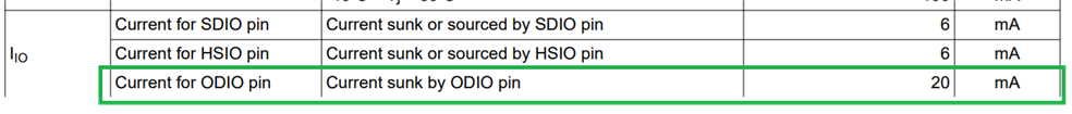
The Texas Instruments MSPM0 microcontroller has a few open drain GPIOs. TI calls them ODIO. These are 5V tolerant, and can switch up to ( see jc2048  comment below) +-8 mA. The main purpose is to support multi-level IO. 
They can do general low side switching too. That's what I'm checking out in this post. I use a ODIO to blinky an LED.

image
image: EasyL1105 controling an LED with open drain IO

The standard GPIOs can source 3.3V, 6 mA (with caveats). Can be used to modestly blink efficient LEDs. But if you want to control a small LCD's backlight, this 5V, 8 mA capability can save a few components.

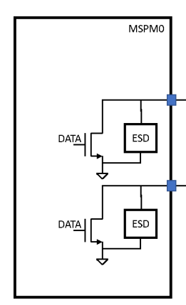
From TI's documentation:

image

"... the open drain IO only implement a low-side NMOS driver and no high-side PMOS driver. The 5V-tolerant
open drain IO are fail-safe and may have a voltage present even if VDD is not supplied"

"ODIO can be used to implement communication with a 5V device."

image
source: MSPM0 L-Series MCUs Hardware Development Guide and MSPM0L110x Mixed-Signal Microcontrollers datasheet

What does this project do?

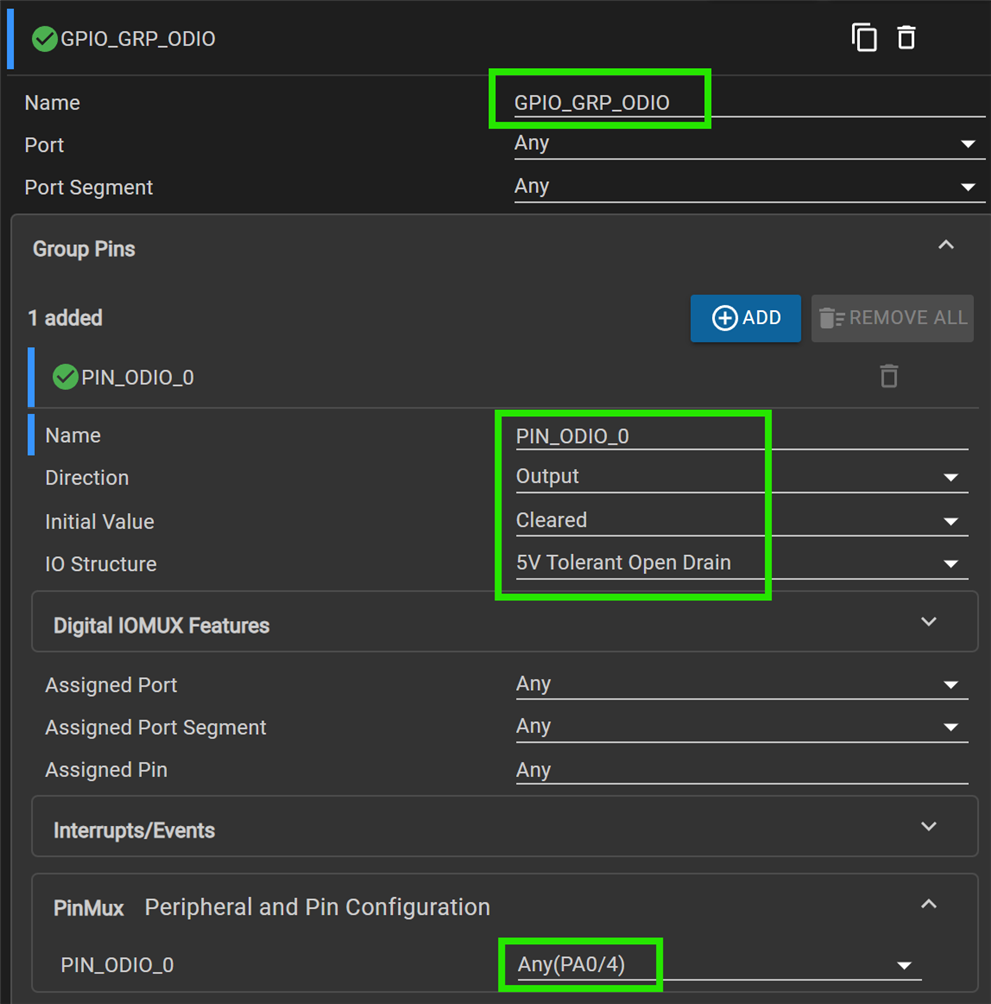
It's the blinky. TI calls it gpio_toggle_output. It blinks an LED every second. The only change I made, is to define open drain pin PA0 as the LED pin. The code is just a simple loop that toggles the pin, then delays half a second.

But what it actually allows you to do, is test that the MSPM0 ODIOs are capable to switch a 5V powered load.

Hardware resources

LED1 PA0 Led with 330R resistor in series
Powered by 5V

The circuit is simple. A red LED with a 330V resistor in series. When PA0's gate is driven high, the current in this circuit, and through PA0's channel, will be around 10  7 mA.

I used the 5V of my EasyL1105 kit. If you use a LaunchPad: they have a 5V supply too.

image

Testing

Program the MSPM0LL05 with the attached CCS project code. If you have a debugger, you can do this from CCS. I've also provided a .hex firmware that can be used with shabaz ' bootloader utility.

Code highlights

In SysConfig, PA0 is set up as an open drain output.:

image

The code is extremely simple:

/* This results in approximately 0.5s of delay assuming 32MHz CPU_CLK */
#define DELAY (16000000)

int main(void)
{
    SYSCFG_DL_init();

    while (1) {
        delay_cycles(DELAY);
        DL_GPIO_togglePins(GPIO_GRP_ODIO_PORT,
            GPIO_GRP_ODIO_PIN_ODIO_0_PIN);
    }
}

What's next? PA0 can be driven from a PWM peripheral. That allows you to dim a small LCD's backlight without external transistors.

Have fun!

ccs project adapted to EasyL1105 (with bootloader compatible .hex firmware): EasyL1105_odio_sink_20251118.zip

Related posts

  • Sign in to reply
Parents
  • jc2048
    jc2048 7 hours ago

    You're quoting the 20mA from the absolute max ratings table. The IOL is 8mA (see the table further down the datasheet).

    That 20mA basically comes down to a dissipation limit for the output transistor (20mW is quite a lot in a small area on-chip) - the metallisation and the bond wires will manage much more than that before fusing.

    Your example is no problem at all because you're only running about 7.5mA through the red LED (not 10mA - you haven't taken into account the rDS-on value for the output MOSFET), and you're pulsing it at intervals which reduces the average dissipation even further. But sinking 20mA DC for a backlight with it wouldn't be good design practice, though it could work for a personal project (the ratings are somewhat conservative and you're not going to be operating it in an ambient temperature anywhere near the top of the spec range, anyhow).

    • Cancel
    • Vote Up 0 Vote Down
    • Sign in to reply
    • More
    • Cancel
Comment
  • jc2048
    jc2048 7 hours ago

    You're quoting the 20mA from the absolute max ratings table. The IOL is 8mA (see the table further down the datasheet).

    That 20mA basically comes down to a dissipation limit for the output transistor (20mW is quite a lot in a small area on-chip) - the metallisation and the bond wires will manage much more than that before fusing.

    Your example is no problem at all because you're only running about 7.5mA through the red LED (not 10mA - you haven't taken into account the rDS-on value for the output MOSFET), and you're pulsing it at intervals which reduces the average dissipation even further. But sinking 20mA DC for a backlight with it wouldn't be good design practice, though it could work for a personal project (the ratings are somewhat conservative and you're not going to be operating it in an ambient temperature anywhere near the top of the spec range, anyhow).

    • Cancel
    • Vote Up 0 Vote Down
    • Sign in to reply
    • More
    • Cancel
Children
  • Jan Cumps
    Jan Cumps 3 hours ago in reply to jc2048

    Checking, because I cut many corners ...

    • Cancel
    • Vote Up 0 Vote Down
    • Sign in to reply
    • More
    • Cancel
  • Jan Cumps
    Jan Cumps 2 hours ago in reply to jc2048

    I'm going to answer the easiest question first.


    > you're only running about 7.5mA through the red LED (not 10mA - you haven't taken into account the rDS-on value for the output MOSFET)

    Checked reality with Ohms law, and the LED on constantly

    R = 328 Ohm

    VR = 2,26 V

    -> IR = 6.9 mA

    • Cancel
    • Vote Up 0 Vote Down
    • Sign in to reply
    • More
    • Cancel
  • Jan Cumps
    Jan Cumps 47 minutes ago in reply to Jan Cumps

    and what my meter thinks:
    image

    • Cancel
    • Vote Up 0 Vote Down
    • Sign in to reply
    • More
    • Cancel
element14 Community

element14 is the first online community specifically for engineers. Connect with your peers and get expert answers to your questions.

  • Members
  • Learn
  • Technologies
  • Challenges & Projects
  • Products
  • Store
  • About Us
  • Feedback & Support
  • FAQs
  • Terms of Use
  • Privacy Policy
  • Legal and Copyright Notices
  • Sitemap
  • Cookies

An Avnet Company © 2025 Premier Farnell Limited. All Rights Reserved.

Premier Farnell Ltd, registered in England and Wales (no 00876412), registered office: Farnell House, Forge Lane, Leeds LS12 2NE.

ICP 备案号 10220084.

Follow element14

  • X
  • Facebook
  • linkedin
  • YouTube