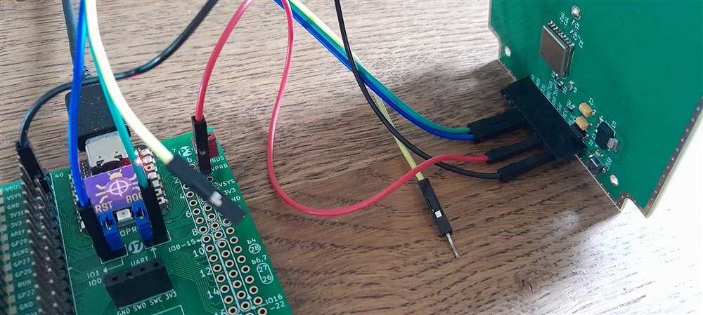
The Teseo-LIV3 GPS module (as used in shabaz ' GPS / Galileo / BeiDou / GLONASS receiver) talks UART and I2C. I'm writing an OO driver for it, for embedded systems. In this blog, how to wire the Teseo PCB to a Pico
Pico connections for I2C, UART and shared functions
Pico resources if you use I2C:
- I2C0
- SDA: GP16 (Pico I2C0 SDA)
- SCL: GP17 (Pico I2C0 SCL)
- baud: 100 * 1000
for I2C, SDA connects to SDA and SCL to SCL
Pico resources if you use UART:
- UART1
- TX: GP4 (Pico UART1 RX)
- RX: GP5 (Pico UART1 TX)
- baud: 9600
- UART1 RX interrupt
for UART, RX connects to TX and vice versa
Pico common resources:
- RESET: GP18 (optional)
- 5V: VBUS
- 0V: GND

Anything else?
Yes: Send UART to a USB comms port while you are developing for I2C:
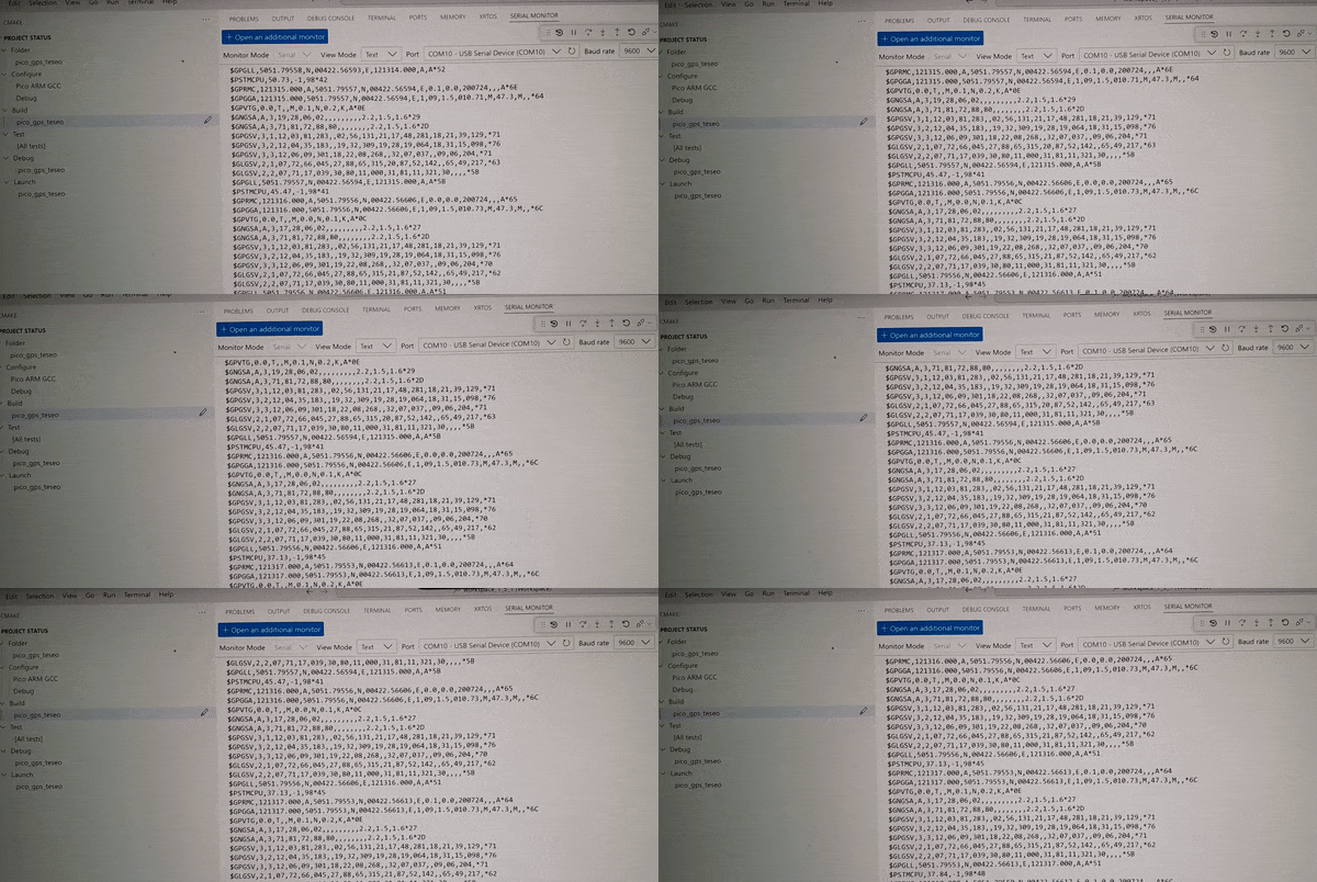
If you use I2C as communication protocol, you can connect the unused Teseo UART pins to a UART-to-USB passthrough. Then use a serial terminal program (PuTTY, etc...) to connect and interact.
There are many UART-to-USB converters available. The simplest is an FTDI serial-to-USB cable. Most debuggers have one on board too. I'm using a XIAO PicoProbe for it, because that's the one on the development board that I use: Pi Pico Eurocard Development Board . See the drawing above for connections.
standard setup: 9600 8 ,1, N

You can send and receive commands via the two interfaces at the same time, but they influence each other. The best use for it is to monitor the unformatted Teseo output constantly in a serial terminal. Or to send commands that change the behaviour as part of an interactive debug/troubleshoot/design session (e.g. a warm reset).
for UART, RX connects to TX and vice versa

Next post: C++ library for ST Teseo GPS - pt. 5: ready for a first (0.1) firmware release
visit the github repository (git clone https://github.com/jancumps/pico_gps_teseo.git)
view the online documentation
Link to all posts.
